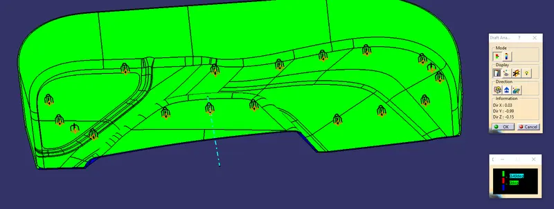
Week 9 - Project 1 - Door Trim Lower with Engineering Features
OBJECTIVE
To create base bracket using given class A
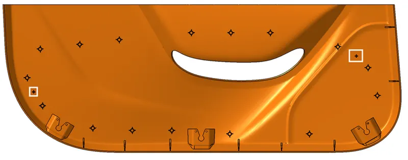
To create heat stakes and fourway locator as show in the image
To create tooling axis
To perform draft analysis
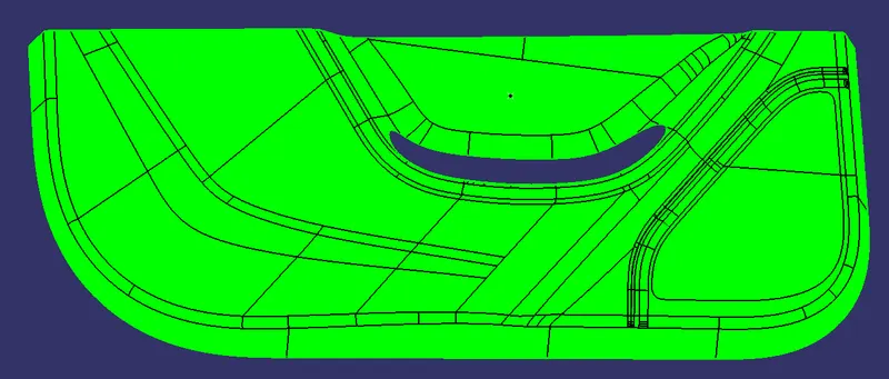
CLASS A SURFACE:
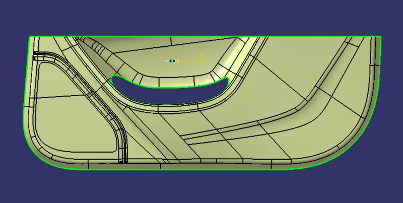
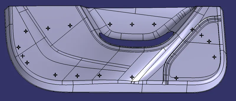
The above image represents the class A surface given as input.
GENERATING TOOLING AXIS:
1. The flat face from the given class A surface is identified and extracted.
2. A point is plated using point option and on surface method.
3. a line is created by using line command normal to surface plane. Thus TOOLING AXIS is created.
CLASS B:
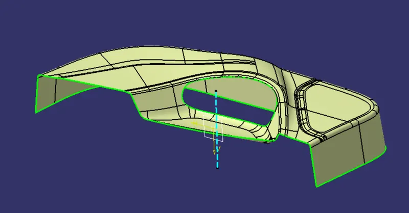
1. The given surface is offseted for the given thickess of 2.5mm.
2. few open patches are found in the class B surface.
3. These patches are closed by creating a boundary and expolated tagential or curvature to the surface for the suitable surfaces.
4. Then they are trimmed.
5. Fillet values are measured and applied. CLASS B surface is created.
CLASS C
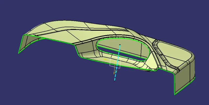
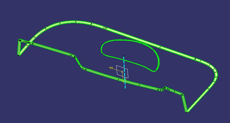
1.The class C surfaces are created part by part up to required distance.
2. The edges are selected and boundary is created.
3. The outer edges are swept using boundary reference surface.
4. The cut out portions are created using tooling axis method using tooling axis
FINAL SURFACE:
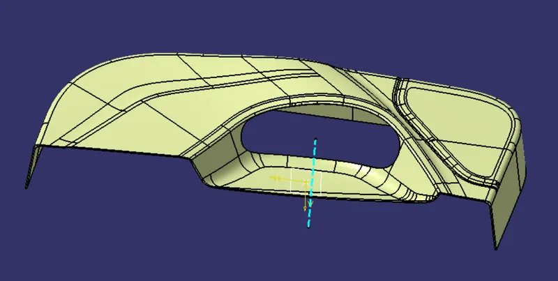
1. The class A and class C surfaces are joined together.
2. The joined surface is trimmed with class B surface and Final surface is created.
CLOSED SURFACE CREATION:
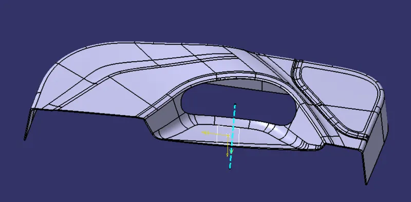
1. By going to part design and using closed surface option. the Thickened component is created.
FOUR WAY LOCATOR:
1. Reference for sketch creation is created using the point and direction method.
2. By choosing any one of the fourway locator point and tooling direction Plane is created.
3. line for four way locator is created and pad option is used with neutral fibre and 2mm in bottom direction.
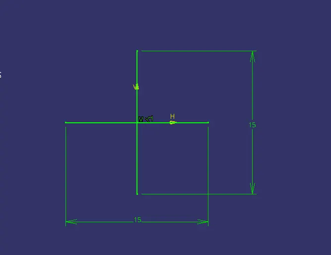
4. Draft for 0.5 degree is given for all the face along tooling direction, ends are chamfered and fillets are applied.
5. second fourway locator is created by using paste special option followed with links.
6. second body is translated using point to point method.
7. These two four way locators are union trimmed with the main body.
HEAT STAKES:
1. The fourway locator created is used as ribs for heat stakes.
2. The circular profiles are created and paded few mm above of ribs and drafted for 0.5 degree
3. the circular part of heat stakes and ribs are union trimmed and created as a single body and pasted special and translated to all the required points. and finally assembled into a single body and union trimmed with the main body.
FINAL COMPONENT:
FRONT:
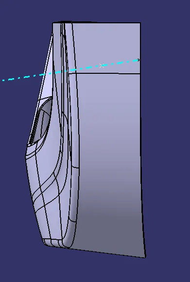
RIGHT:
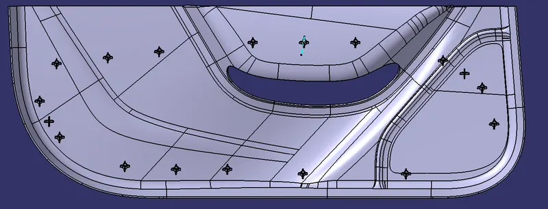
CLASS A DRAFT ANALYSIS:
FINAL COMPONENT DRAFT ANALYSIS: