Week 9 - Project 1 - Door Trim Lower with Engineering Features
#DOOR TRIM WITH LOCATORS AND HEAT STAKES#
1) AIM :- Thicken the Door Trim, add Two- and Four- Way Locators and Heat Stakes according to the design rules and verify with draft analysis.
2) INTRODUCTION :-
A) HEAT STAKES :-
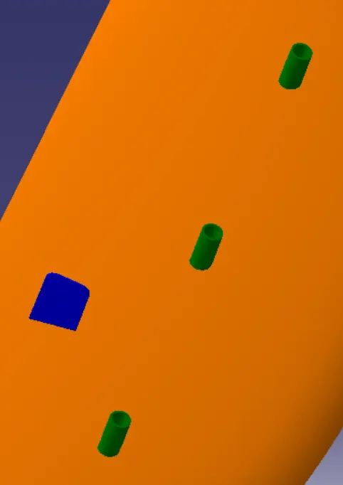
Heat staking also known as thermoplastic staking is the process of joining two dissimilar materials together. In heat staking we use local heating and cooling to raise the temperature of plastic components and allow plastic reforming to be carried out. This reforming can be used in a wide variety of applications.
B) LOCATORS :-
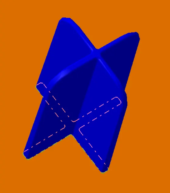
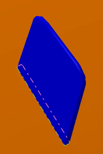
A round locating pin located concentrically in a hole is a common application of a 4-way pin, and helps to further secure the piece. 4-WAY LOCATORS: 4-way mean you prevent movement at 2 axes (+X, -X, +Y and -Y) on the plane. Generally, you have cylindrical pin on the fixture and circular hole at workpiece part.
3) COMPLETED DOOR TRIM :-
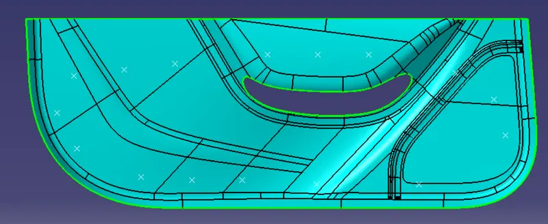
We were provided a Class A surface as below, with locations for Heat Stakes.
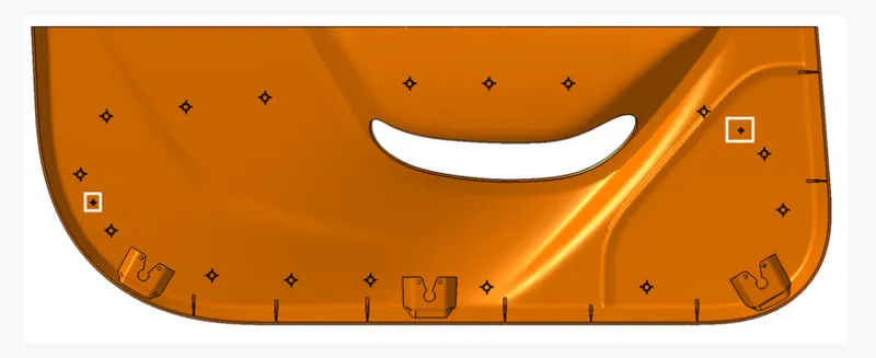
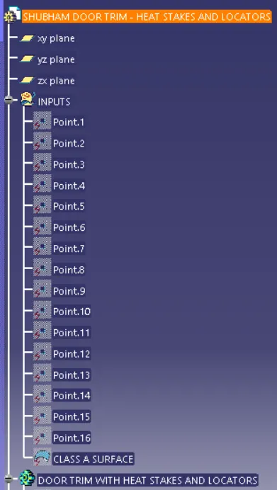
A) DOOR TRIM INPUTS WITH HEAT STAKES POSITIONING :-
4) OBJECTIVE :-
- Create Tooling axis for the given CLASS -A surface.
- Create the CLASS B and C surfaces of door trim using the given CLASS-A surface.
- Create final surface model and convert it into solid body using close surface command in the part design workbench.
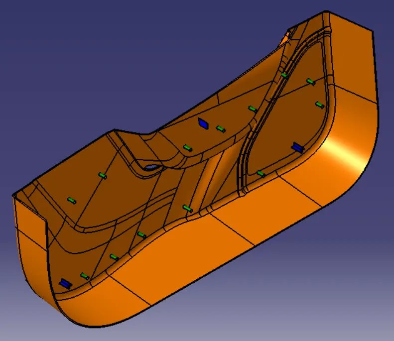
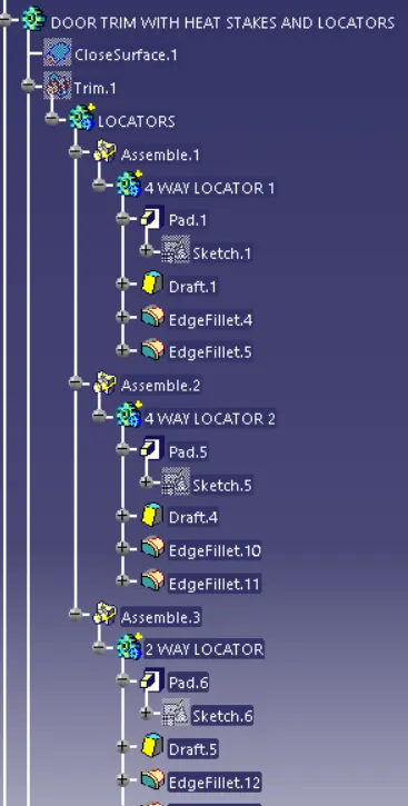
- Create two 4 way locator , 2 way locator and 16 heat stakes from given input points considering the design rules.
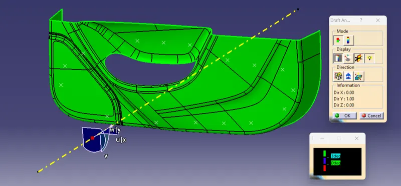
- Perform draft analysis for both Class-A surface and Final part body.
5) DESIGN METHODOLOGY :-
Class-A surface means visible surface. It gives the aesthetic of the component which is created by the styling team and gives to the part design engineer to create the part with all engineering aspects.
6) PROCEDURE FOR CREATION OF MAIN TOOLING AXIS :-
- Check the best possible tooling direction by manually adjusting the compass.
- By analysing it is found that y axis as tooling direction would clear most of the faces without any difficulties.
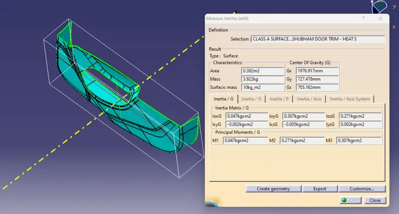
- Now a create point on center of gravity of door trim using measure inertia.
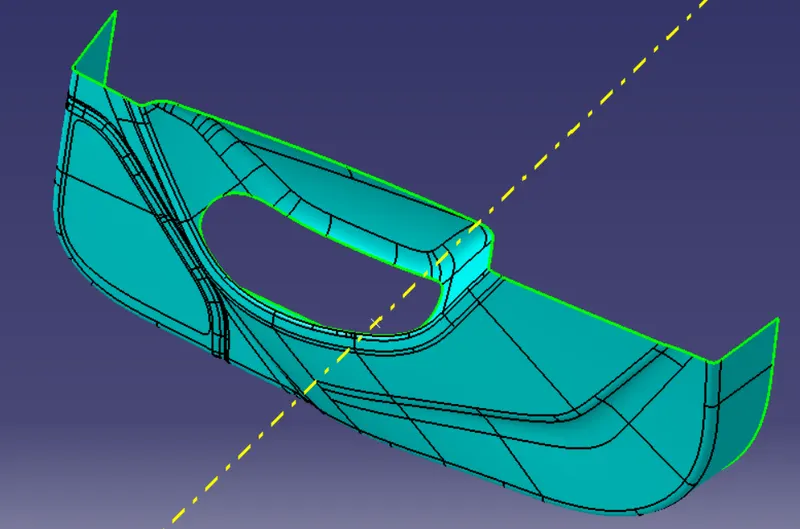
- Then create a line with point 1 in y direction and name it as main tooling axis .
- Colour the main tooling axis as yellow and publish it .
A. CLASS A SURFACE WITH DRAFT ANALYSIS :-
7) CLASS-B SURFACE CREATION :-
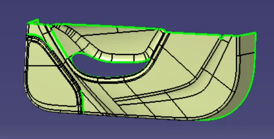
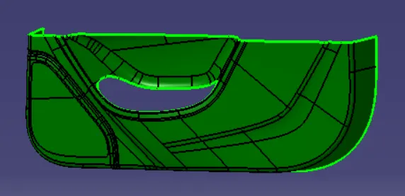
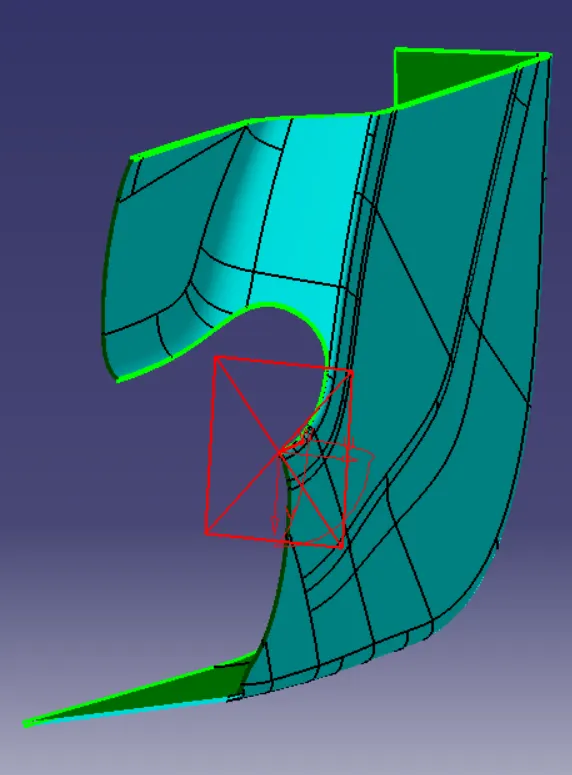
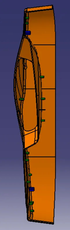
Class-B surface means thickness of a part it is not visible and is inside part. In other words, Class-B surface is a surface below a certain thickness from the class-A surface. This is the surface that contains engineering aspects of a model.
- Create offset surface of CLASS-A about 2.5mm inward direction.
- Check for the discontinuity and rework on the offset surface using extract, multi-extract, multi sections surface.
- Join the surfaces and ensure the final CLASS-B surface created has no gaps.
A. CLASS B SURFACE WITH 2.5 MM OFFSET , SECTIONAL VIEW :-
8) CLASS-C SURFACE CREATION :-
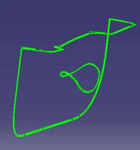
Surface that joins class-A and class-B surfaces is class-C surface. Class C is often specified for interior surfaces not readily visible, surfaces that will be covered by another part when assembled :-
- Create the sweep surfaces with reference to surface and tooling axis by multi extracting the CLASS-A boundaries.
- Join the sweep surfaces by using commands like extrapolate, trim, multi section surface.
- Finally join all the sweep surfaces and ensure the continuity of the CLASS-C surface.
9) CREATING THE FINAL SURFACE :-
- For creating the Finals door trim surface, join the CLASS-A and CLASS-C surface together.
- Then Extrapolate the B surface little bit outward direction to make sure that there would not be any gap when trimming with joined surface.
- Then trim the extrapolated CLASS-B surface with Join surface (CLASS-A and CLASS-C).
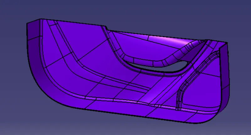
Make a solid part body using the CLOSE SURFACE command in INSERT then SURFACE BASED FEATURES in the PART DESIGN WORKBENCH .
After creating the Tooling Axes, we then thickened the Door Trim based on the completed Door Trim Class A, B and C surfaces. We next added Two Four-Way and One Two-Way Locators, and Sixteen Heat Stakes according to the respective design rules, with wall thicknesses of 1.3 mm and heights of 20 mm , 14mm and a draft of 0.5 degree on each side faces respectively.
10) 3D PART MODEL IN VARIOUS ORIENTATIONS :-
A. ISOMETRIC VIEW :- B. FRONT VIEW :-
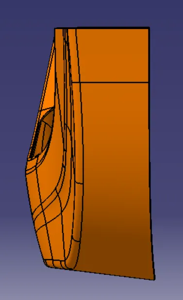
C. SIDE VIEW :- D. TOP VIEW :-
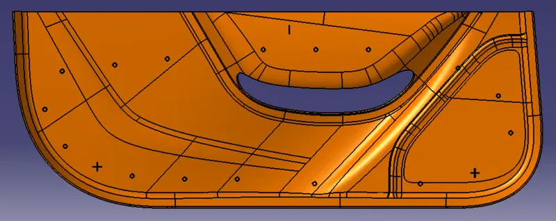
11) DRAFT ANALYSIS OF 3D PART MODEL :-
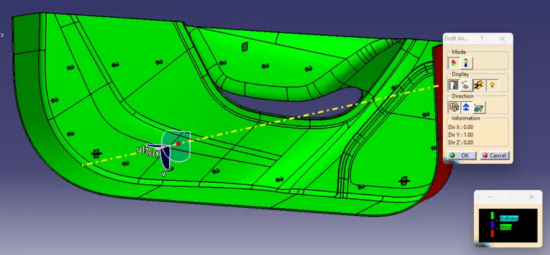
The Draft Analysis as shown above validated the design for manufacturability.
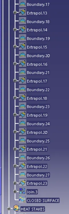
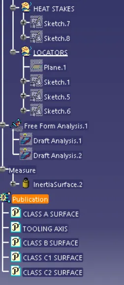
12) EXPANDED TREE STRUCTURE FOR THE GEOMETRICAL SETS AND THE PART BODY :-
TREE 1 :- TREE 2 :- TREE 3 :-
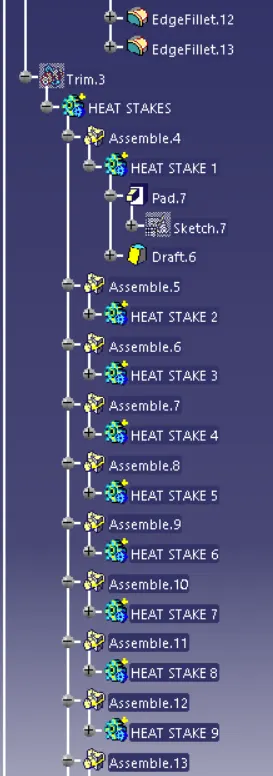
TREE 4 :- TREE 5 :- TREE 6 :-
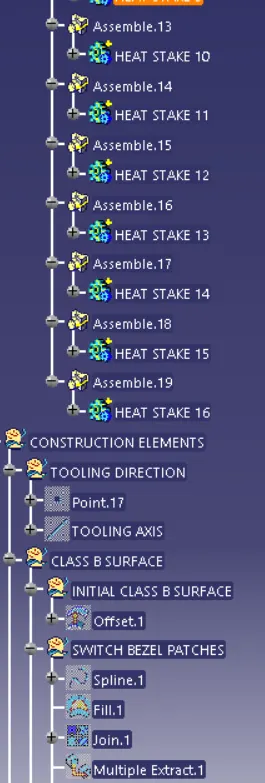
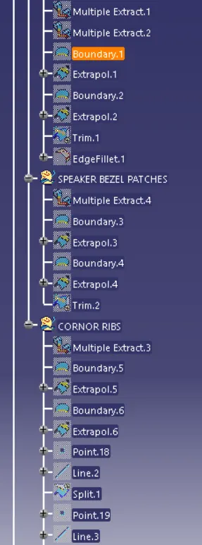
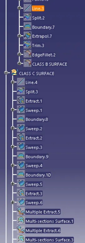
TREE 7 :- TREE 8 :- TREE 9 :-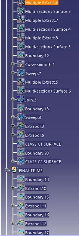
13) CONCLUSION :- We were able to successfully model the thickened Door Trim with Locators and Heat Stakes and successfully verified the component for Draft Analysis.