Door Trim Lower with Engineering Features
OBJECTIVE
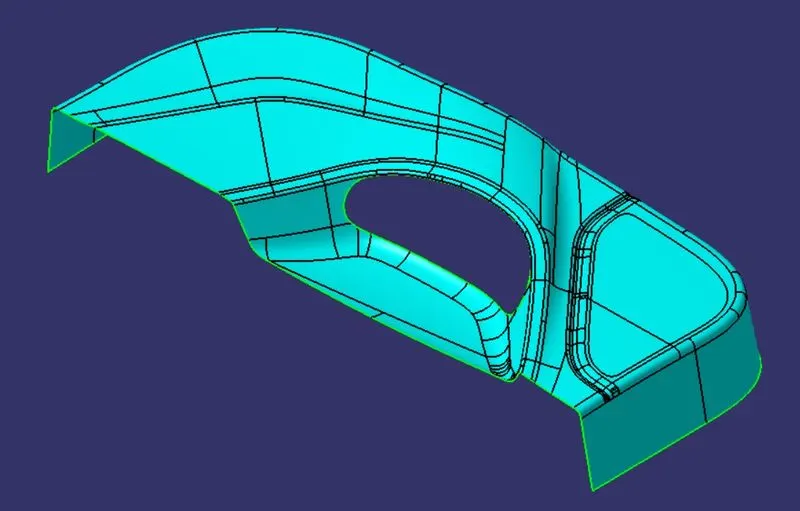
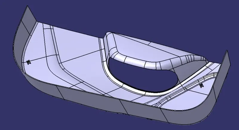
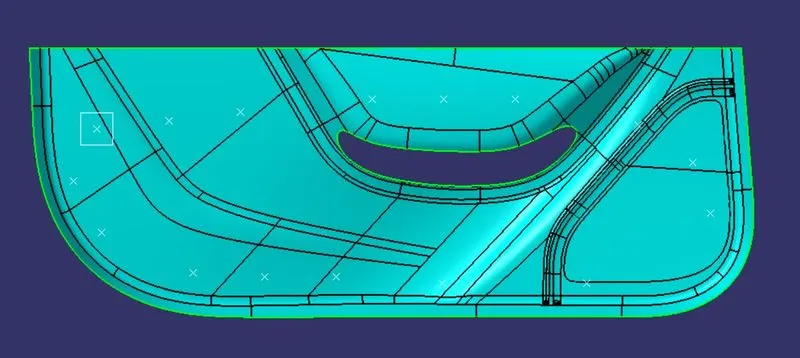
- To design the DOOR TRIM LOWER Plastic component using the given Class-A surface.
- To create the Heat Stakes and the locators considering the design rules mentioned.
PROCEDURE
1. Defining a Tooling axis for the Class-A surface
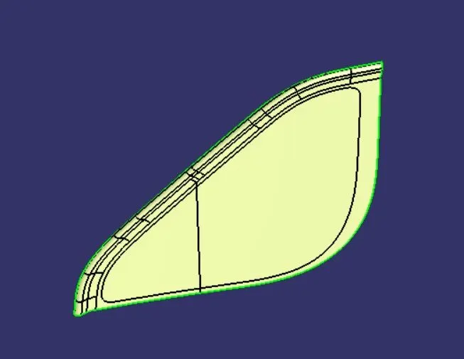
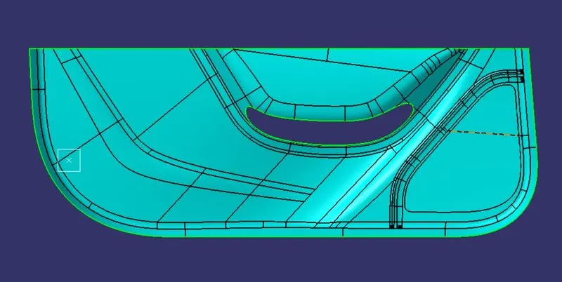
- Step 1: Check the connectivity of the surface and ensure there is no gap in the class A surface. The boundary command helps by highlighting the boundary of all the edges thus we can visually check for gaps in the class A surface.
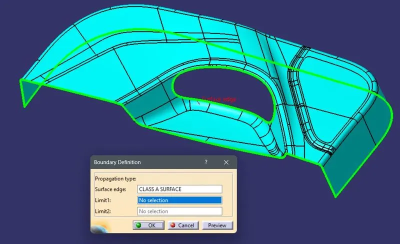
- Step 2: We observe the component from all three principal axes to get an optimum tooling axis direction. In this case, for the Door Trim Lower, the Y direction is the optimum tooling direction.
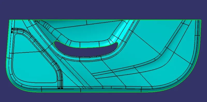
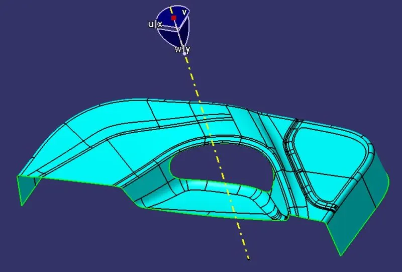
- Step 3: Next we create a point at the center of Gravity of the Door Trim Lower and create a line along the Y direction. This is the main tooling axis.
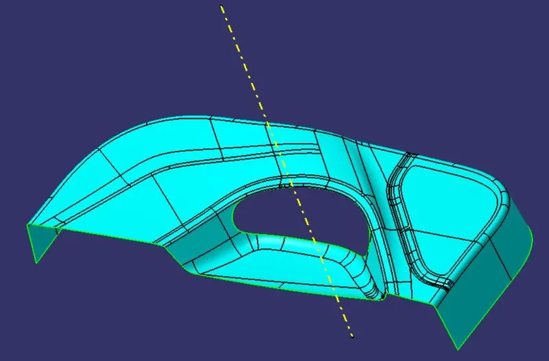
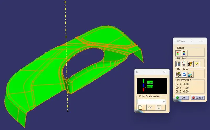
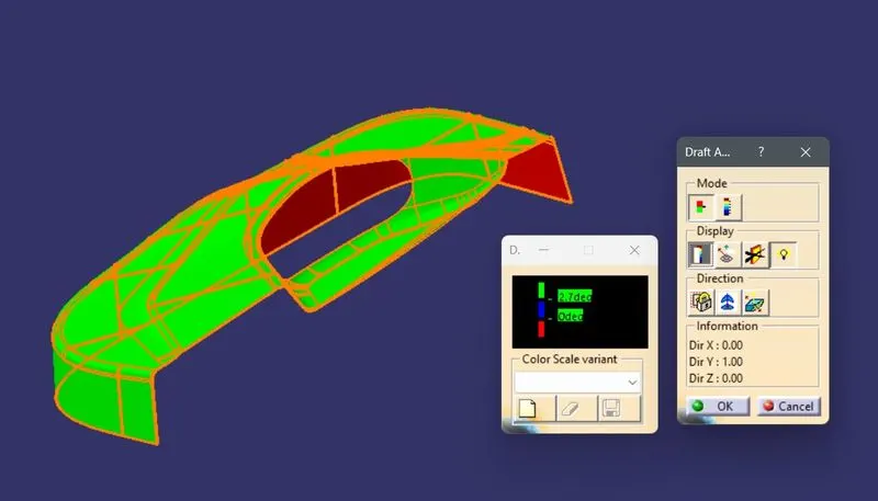
- Step 4: We perform a draft analysis on class A and check the angles of the surface we think will create problems in tooling.
2. Creating Class B surface
- Step 1: We offset the Class A surface to 2.5 mm towards the rear of class A.
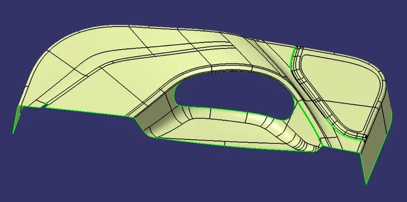
- Step 2:We observe a few gaps and discontinuity in the offset surface.
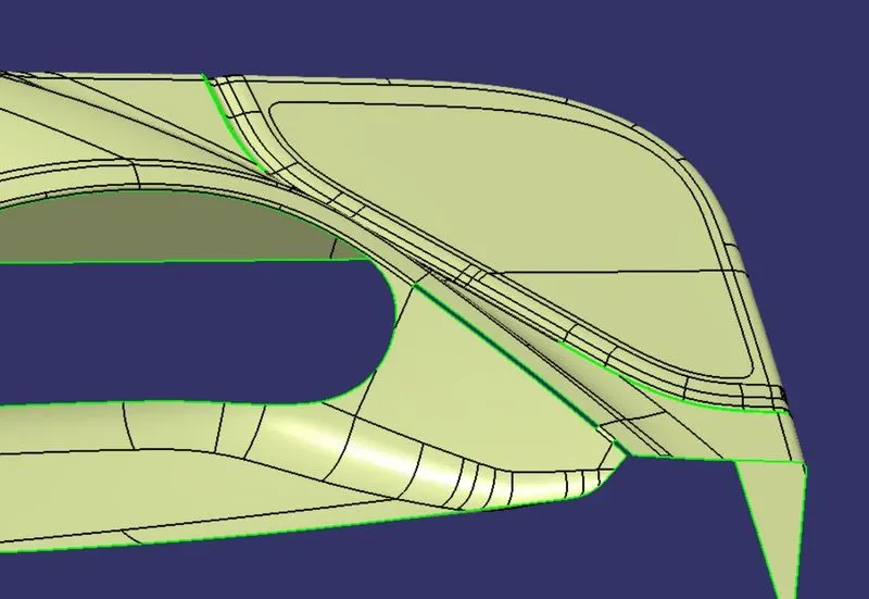
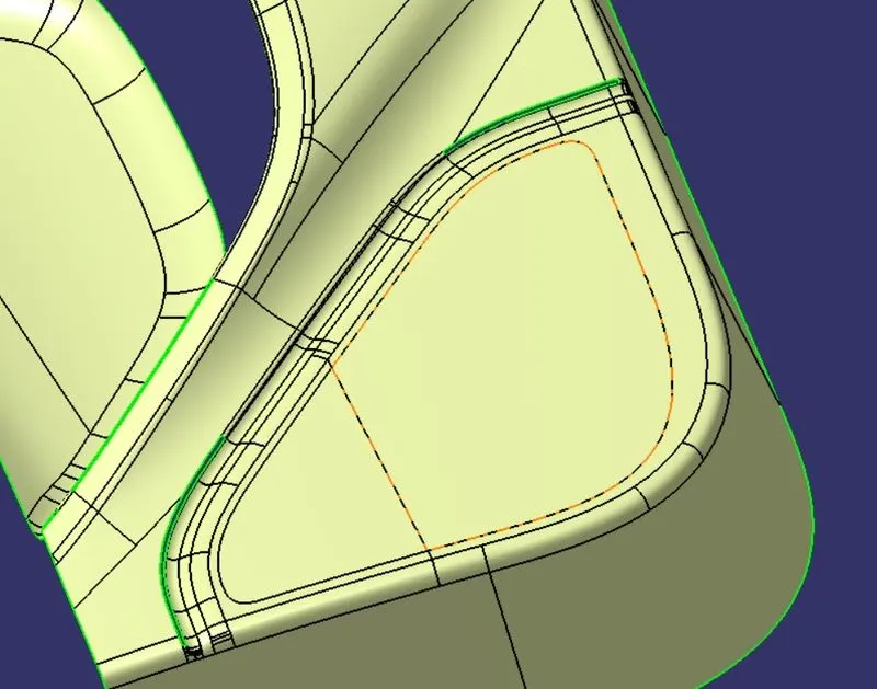
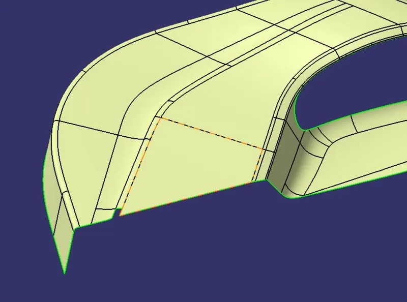
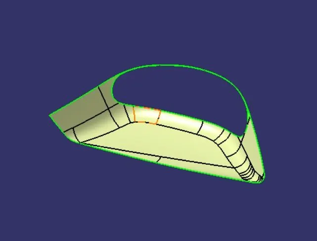
- Step 3: We remove the fillets from around the central pocket. We disassemble the door trim into two independent surfaces and extrapolate them and trim them together and edgefillet with 2.5 mm to repair.
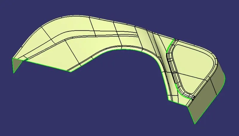
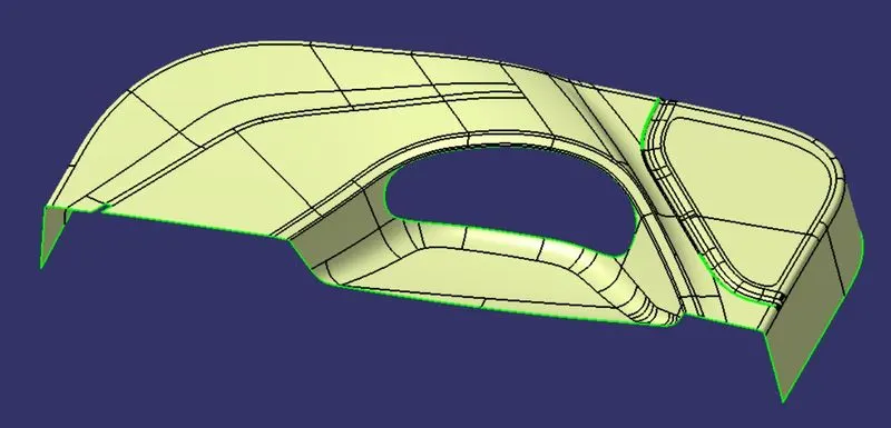
- Step 4: Similarly, we remove the fillets from the side flanges, and the speaker panel of the door trim lower. We disassemble the side flanges, the speaker panel, and the door trim lower into independent surfaces and extrapolate them and trim them together and edgefillet with 1.5 mm and 14.8 mm to repair the door trim fully.
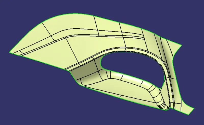
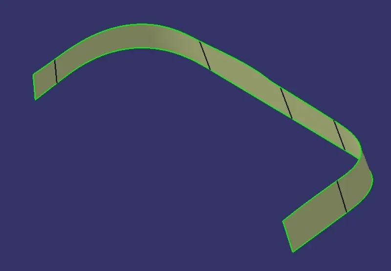
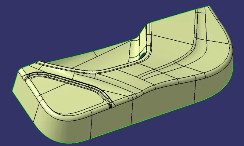
- Step 5: The surface we get is the B surface.
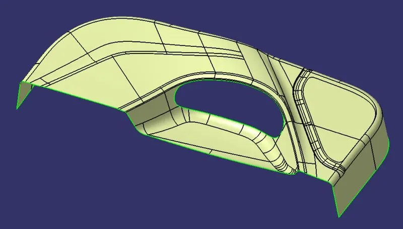
3. Creating Class C surface
- Step 1: We use the boundary command to extract the top edge boundary and smoothen the curve. we use sweep along the tooling surface and 3 degrees as draft angle to get the C surface for the top edge.
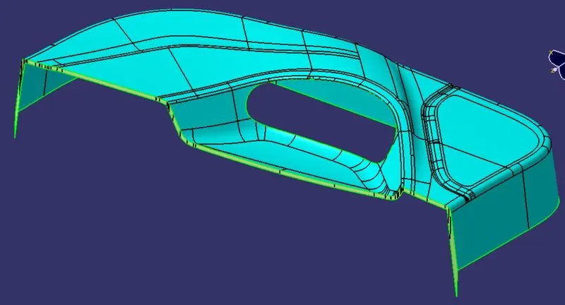
- Step 2: We use the boundary command to extract the flange boundary and smoothen the curve. we again use sweep with a reference surface and at 90 degrees angle to get the C surface for the flange.
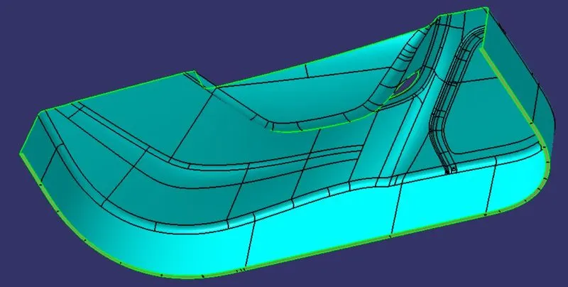
- Step 3: We use the boundary command to extract the central hollow boundary and smoothen the curve. we again use sweep with a reference surface and at 90 degrees angle to get the final C surface for the central hollow.
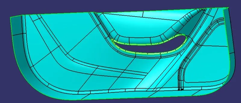
- Step 4: We trim the surfaces of the flange and top edge to get the final C surface for the outer edges.
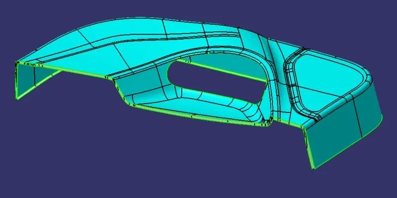
4. Creating the hollow surface part
- Step 1: We use the join operation to join the Class A, and C surfaces and trim them with Class B surface into one body to get the final surface body.
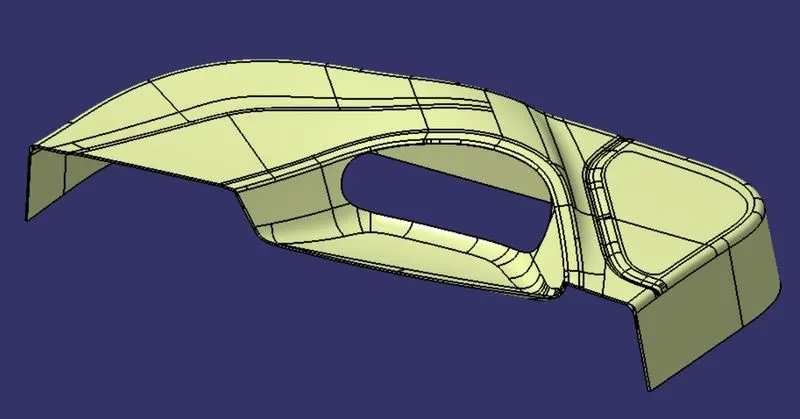
5. Creating the 4-way locator
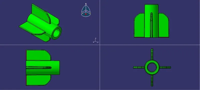
- Step 1: We create a point on the A surface where we want the 4-way locator and create a place offset from the ZX plane at that point.
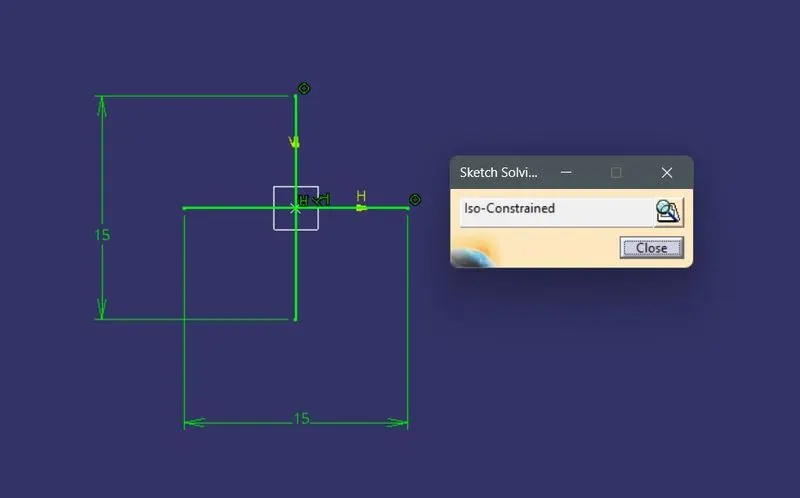
- Step 2: We create a positioned sketch of the 4-way locator for 15mm.
- Step 3: We then pad the sketch with thick for 1mm wrt the neutral fiber for a height as per the design rule for ribs i.e., <=5T.
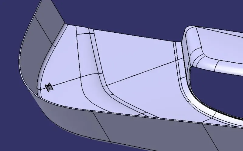
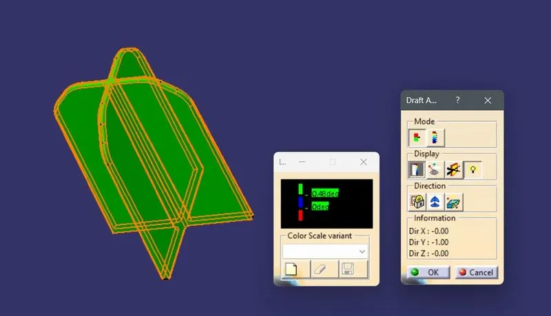
- Step 4: We draft the surfaces along the tooling axis for a minimum of 0.5 degrees and create a chamfer of 3mm and edge fillet with R=0.25mm.
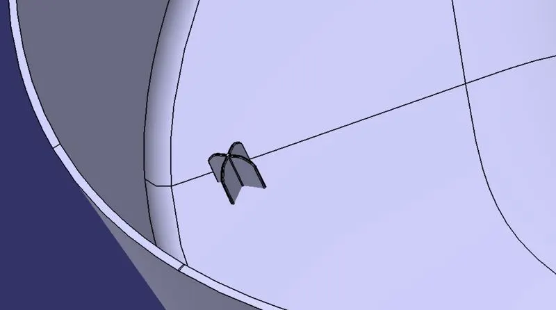
- Step 5: We copy and paste special with link to create a duplicate of the 4-way locator in a new body and translate it to the required place and union trim with the main part to fix the locators.
6. Creating the heat stakes
- Step 1: We create a plane offset from the ZX plane at one of the reference points.
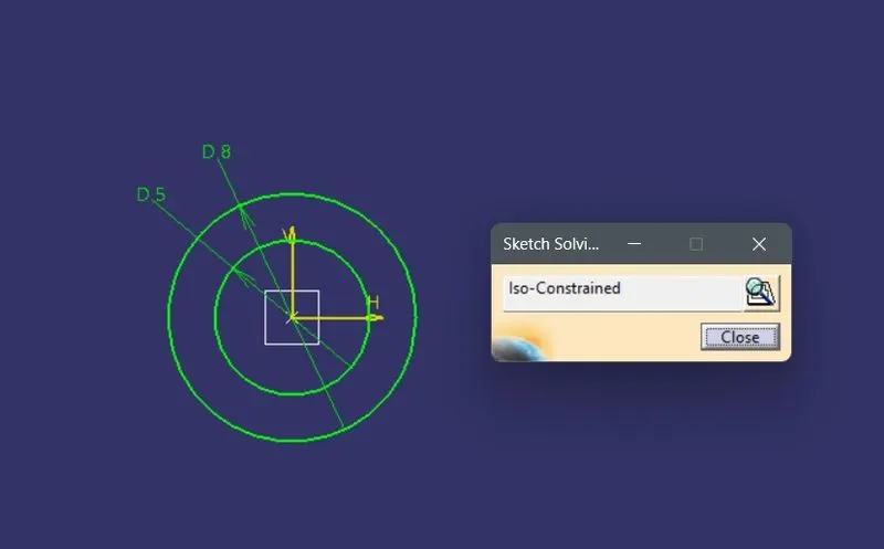
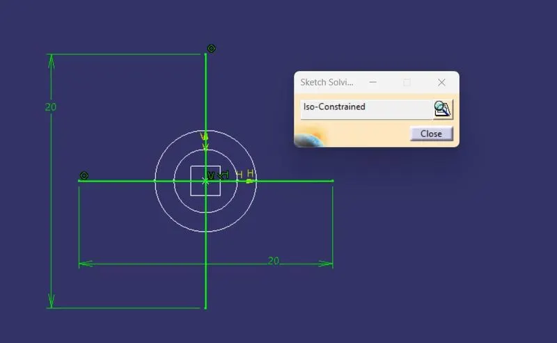
- Step 2: We create a positioned sketch of the heat stakes with ID=5mm and OD=8mm(2*0.6*T).
- Step 3: We then pad the sketch for a height <=5T.
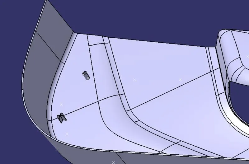
- Step 4: We draft the surfaces along the tooling axis for a minimum of 0.5 degrees and edge fillet with R=0.25mm.
- Step 5: We then create supports as we created the locator and union trim with the circular pad and edgefillet with R=0.25 to get the heat stake.
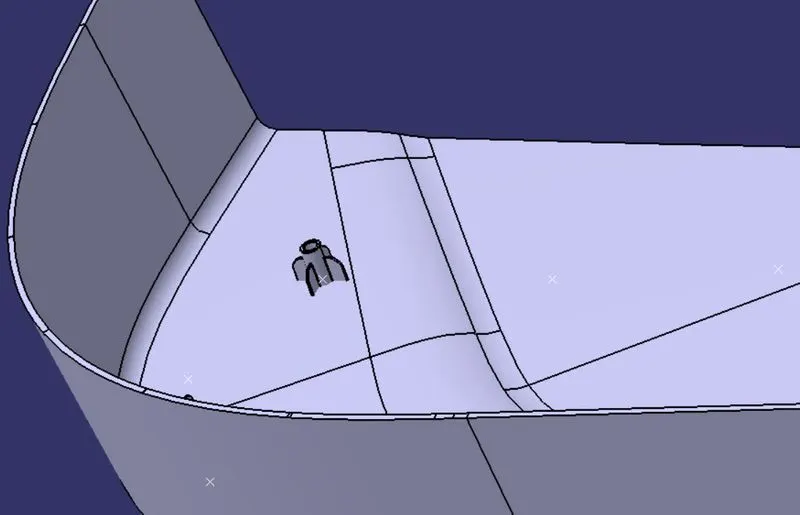
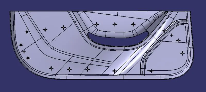
- Step 6: We make 15 duplicates of the above heat stake and translate them to all the reference points and do the final union trim with the part body to assemble them.
7. Publication of the Tooling axis, Class A, B, and C surfaces
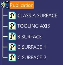
- Step 1: We select the tooling axis, class A, B, and C surface from the tree and go to Tools->Publication to publish them.
8. Creating the final solid component
- Step 1: We switch to the part design workbench and use the Closesurface feature to create the solid part out of the hollow surface body.
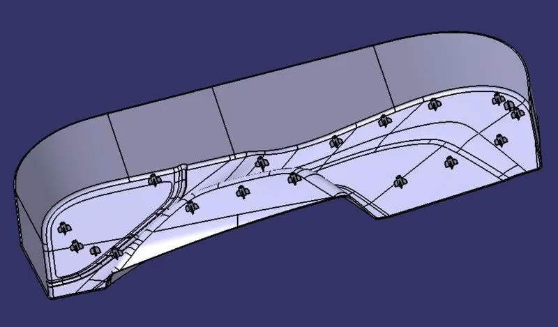
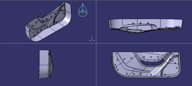
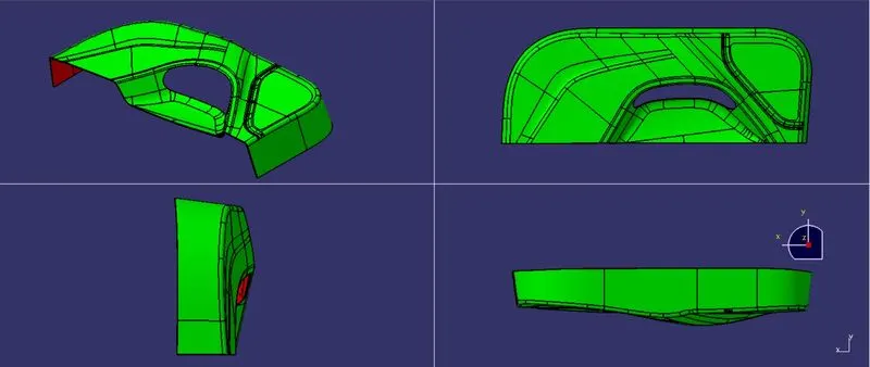
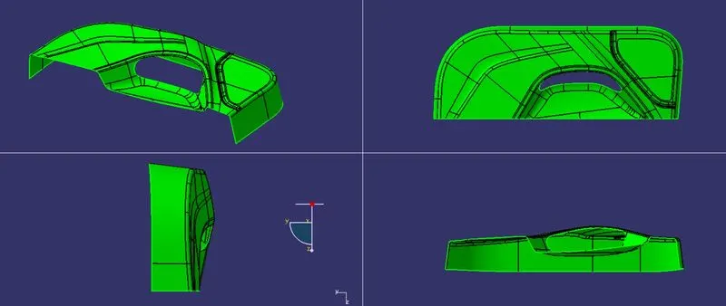
all views
9. Draft analysis on the final component
- Step 1: We open the draft analysis command box and select the compass and drag and align it with the tooling axis and lock it.
- Step 2: We analyze the color scale and input 2.7 degrees as the draft value and save the analysis.
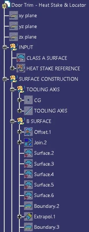
TREE STRUCTURE
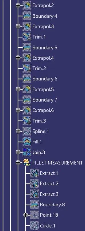
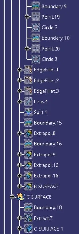
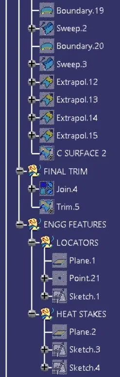
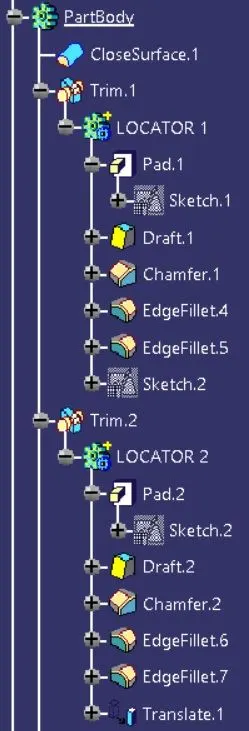
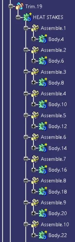
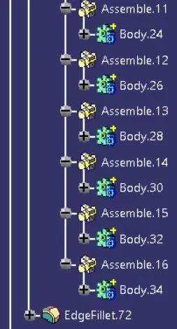
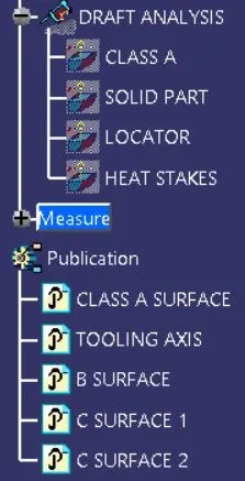
DRAFT ANALYSIS
1. For the final plastic component
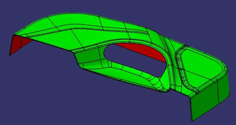
All views
2. For the Class A Surface
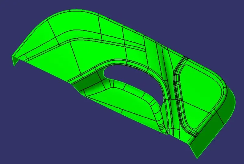
All views
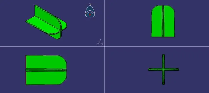
3. For the 4-way locator
all views
4. For the heat stakes
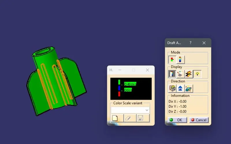
all views