Week 9 - Project 1 - Door Trim Lower with Engineering Features
Challenge -29 Door Trim Lower with Engineering Features
Objective : The main aim this challenge is to create a solid body of Door Trim Lower' with the help of the closede surface method by using the 'generative shape design' workbench in CATIA V5. Performing the 'Draft Analysis' on the solid part body of the Door Trim.
Given Sample Design:
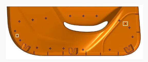
Overview:
Initially, we need to offset the given Door Trim Class A surface in the inner direction to the required thickness ( here the thickness is 2.5mm). After that, we need to close the patches on the offset surface of the bumper, the patches are formed due to the fillets on the class A surface . Once all the patches are closed prperly join them together to make a proper class B surface and now sweep the boundary of the class A surface to trim with the class B surface to make a closed body. By using the closed body command in the part workbench we can get the solid body from the closed surface of the Door Trim Now. I ceated the heat stakes and locaters by considering all the design parameters. After creating all the B-side features on the soid part body of the door trim. I performed a draft analysis for it to check wether all the surfaces are drafted properly or not ( THe daft angle for the plastic component is 0.5 degree to 3 degree).
Tooling Axis:
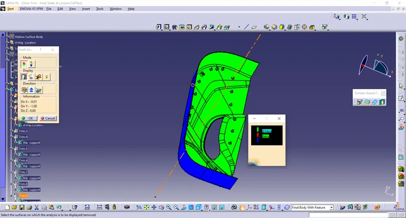
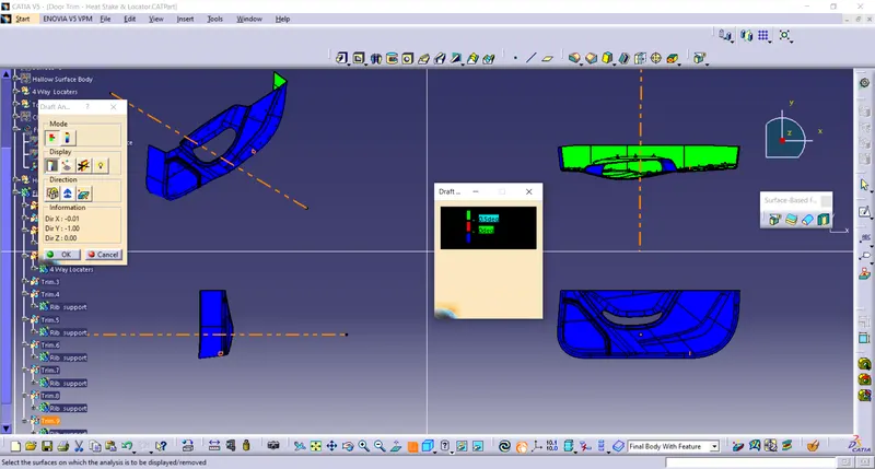
To create the tooling axis , I extracted a surface from Class A and created a point in the middle of the surface by using the point command and created a line at that point through the X- Axis. Now I performed a draft analysis check fromthat line wether the created tooling axis is in the correct position or not. If in the draft, analysis check the surface highlighted with green colour on both sides of the surface the tooling axis is in the correct position and direction.
Draft Analysis for Class A Suface:
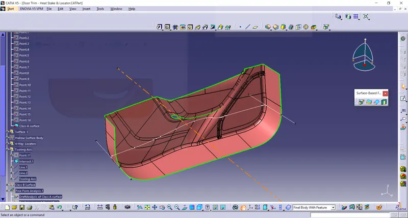
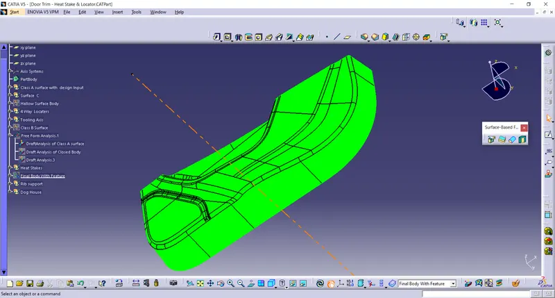
We do perform the draft analysis check for class A surface before we make solid and creation of B side features. iinitially I align the compass to the tooling axis and I gave a 3 Degree draft angle for the green colour in the colour bar. If the surface is highlighted in green colour the draft angle is given properly for class A surface. If the Class A surface is not highlighted fully in green colour, that might be the reason for the draft angle of the class A surface.
Class B Surface:
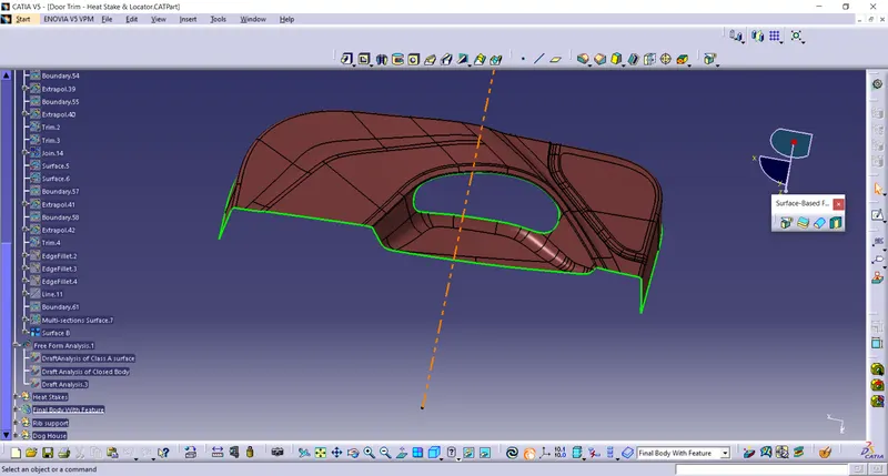
To Create the Class B surface. offset the class A surface inside as per our thickness requirement (here the thickness is 2.5mm , soi offset the class A to 2.5mm inside). Once the offset is created, we can observe some patches on the offset surface by taking the boundary for the offset surface, those patches are formed due to the fillets on the class A surface. Weneed to cover those patches with the helpof the muti-section surfaces command by extracting the patch boundaries. Once all the patches on the offset surface, to get the repicated surface of the class A surface.
Class C surface:
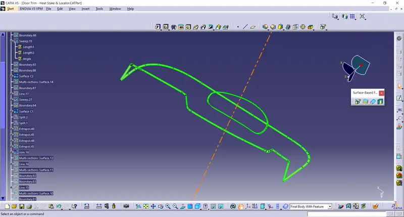
I used the sweep command to create the class C surface concerning the boundary of the class A surface. Initially, Iextracted the boundary of the class-A surface with tangent contuinity and I sweep the extracted boundary concerning the surface at 93 degree ( for draft angle) for 4mm to intersect properly with the class B surface. Once we sweep all the surface boundaries of class A. extrapolate the sweeped surfaces. until both surfaces got intersect properly, and trim them to remove extended extrapolated surfaces to get a proper sweep boundary throught the entire surface, incluiding the centre hole of the door trim. Now, join both class A and swep boundary to get the complete class C surface.
Part Body:
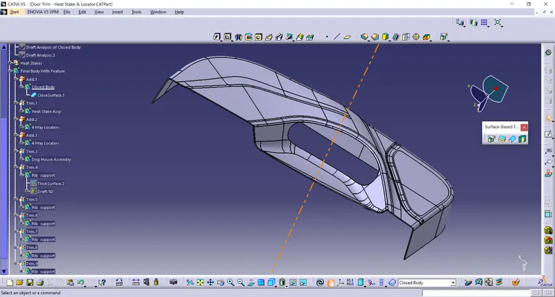
To create the solid part body from the closed surface , I used the closed surface command inthe part workbench.
Creatlion of Locaters:
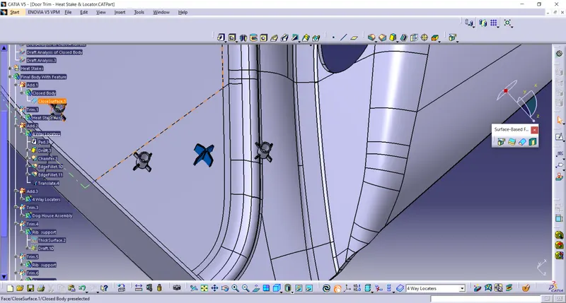
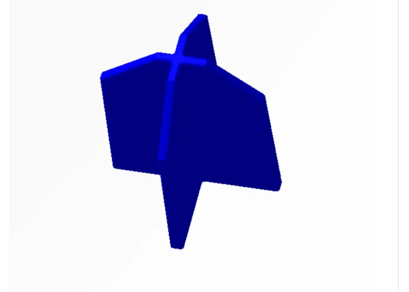
To create the locaters, I created a sketch on the body. Aftercreating the sketch. I pad it 20mm in height and thicken itto 1.3mm and I drated it with 0.5 degree in the direction of the tooling Axis . I gave 5 mm ogf chamfer with 45 Degree of inclination and after I gave a fillet of 0.25mm radias.
4-Way Locaters
Creation of heat Stakes:
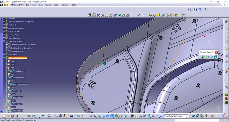
T0 Create the heat stakes, I draw a sketch on the surface. After the creation of the sketch, I pad it to 18mm height and I gave a draft angle of 0.5 deg on both sides (inside and outside) and then i gave a fillet with a 0.25mm radias. After Creating the heat stake. I created the ribs for supporting purposes. To create the ribs, I draw a sketch and padded it to 12mm in height and 1mm thickness. After padding the ribs, I dafted 0.5 deg in the tooling Axis direction and filleted it with a 0.25mm radias. Finally, I union trim the ribs with a heat stake to remove the ribs, which are present inside theheat stakes.
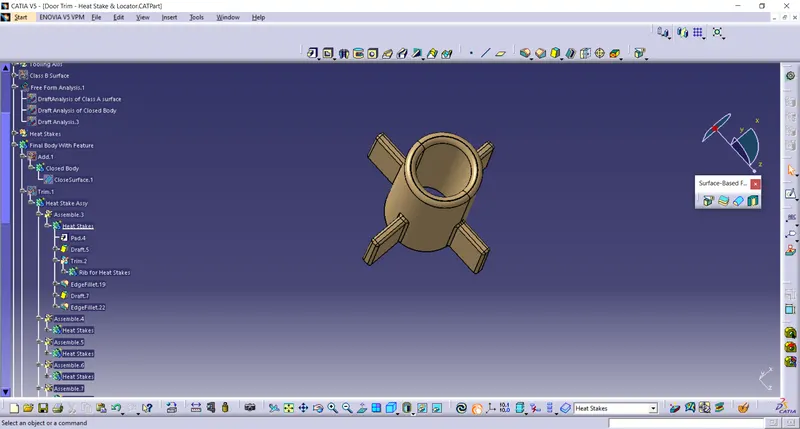
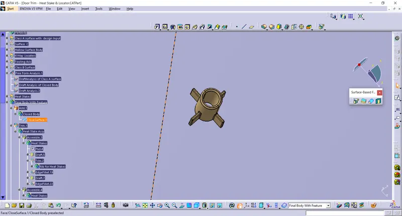
Heat Stake with supporting ribs
Now I Power copy the heat stakes by giving inputs like point and plane copy them in the part body according to the requirement
Final part body with 4-way locaters incluiding all the heat stakes with supporting ribs.
Creation Of Ribs:
Ribs are a feature in plastic injection molded parts . They are thin extension that run perpendiculer from a wall or plane. They are commonly used to provkide additional support and strength to apart. Thickness and location are essential to rib design.
To create the ribs, I draw a sketch and padded it to 12mm in height and 1mm in thickness. After padding the ribs, I drafted 0.5 degree in the tooling axis direction and filleted it with a 0.25mm radius.
Use power copy to produce rib and another two ribs are produse using translate command to have command on both the steps.
Creation of Dog House:
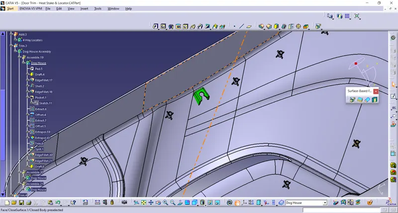
Dog house is an engineering feature used in plastic trim design. Dog houses are used as supporting feature. Sometimes other engineering features like snaps: locaters etc. are molded on them to increase their strength.
- To create the Dog house, I draw a sketch and padded it to 18mm in height.
- After padding in the direction of tooling Axis, I drafted 3 degree in the tooling axis direction and filleted it with a 3mm radius.
- Than i remove the material from the base of it having a thickness of 0.4xT = 1mm.
- Than provide draft it to 0.5 degree in the direction of side core axis.
- Then shell the main padded structure to 0.7xT = 1.75mm.
- Remove th second body from the first body.
- After joining both the bodies translate it to required points and rotate it with respect to its edge.
- After producing all the dog Hous untrimit withthe solid surface priously prodused the final prodused solid body having all the features shown below.
Draft Analysis of A Part Body with Features