Week 9 - Project 1 - Door Trim Lower with Engineering Features
At first we have to make the Solid surface.For that we have to make Class C Surface and Class B Surface from the Class A surface.
The aim is to generate the Class B and Class C surface from the given Class A Surface.So,the main overview/important steps for this operation is
- Creation of the Tooling axis
- Perform the draft analysis on given tooling axis
- Offset the Class A surface to given thickness
- Clearing the patches of offseted surface
- Performing the sweep command
- Finally making a closed body
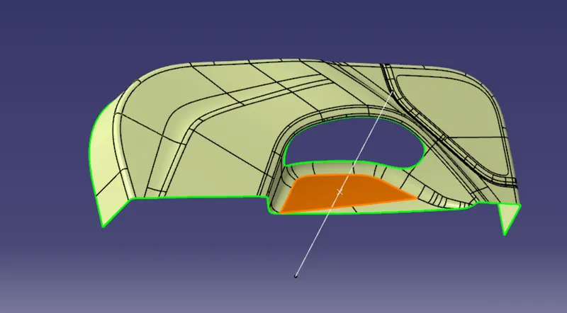
The above figure is our Class A surface.We want to select a flat surface from it.
So here we are selecting the highlighting surface as the flat surface.We have to put a point on the surface and give line normal to surface on it.
Next we have to perform the draft analysis
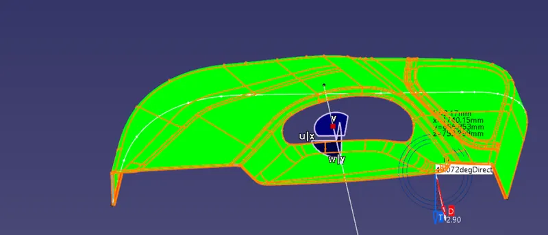
For that click on the draft analysis,and put the compass into the tooling axis.Make sure that tooling axis and the compass are perfectly alligned.Click on anywhere on the surface.If it is appearing the greenline it is confirmed that draft is cleared.Then we can proceed to next step.
Now the draft analysis is done.Next step is to offset for the given thickness i.e 2.5mm.Some patches will appear.So for clearing patches the steps taken are
- Divide the body into four halves
- Extract the four surfaces using multiple extract excluding all the fillets
- Recreate the fillets by extrapolating and giving the fillets
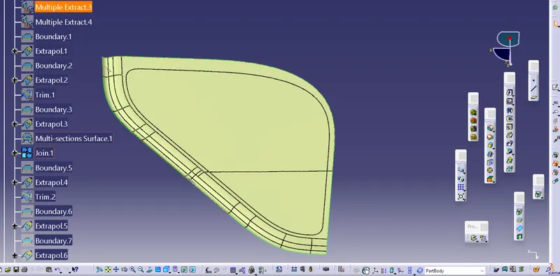
In the case if it is hard to recreate then we can remove this surface by complementary mode by again created by extrapolating and giving the fillets
Then we have to move creation of C surface
For creation of the C surface we have to use sweep with draft direction
But while using the sweep with draft direction there will be possibilty to form the sharp edges.So it is recommended to use sweep with reference surface in that sharp edge forming portions.Inorder to obtain quality surface divide itinto multiple boundaries and then sweep seperately
Trim the surfaces after sweep after extrapolating and join all the C surfaces together
Then join with A and C
Next step is to join A+C Surface with the B surface.Before that we have to extrapolate the B surface.There might be some issues while extrapolating the B surface.An error will show forming the cusp.So,it is recommended to divide to multiple boundaries and extrapolate seperately.
The next step is to trim B surface with the A+C Surface.For that we have to check for intersections.If the intersection is not perfectly happened,extrapolate it furthur that particular surface
Then we will get the trimmed surface
Put it in part body and make it in closed surface
Again perform the draft analysis
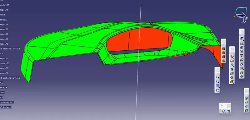
As the design rule regulations,first we have to create the fourway locator
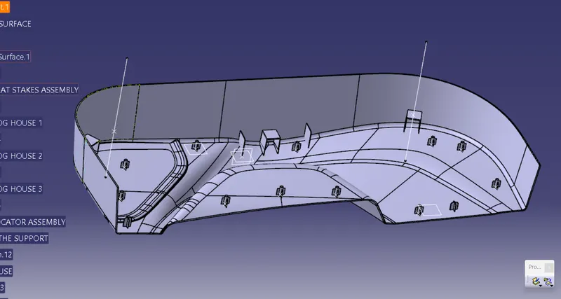
So,inorder to create the Locator first we have to make the sketch on the solid body as 15mm each side as shown in the below figure .
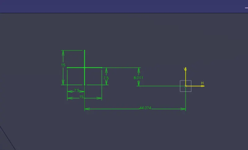
Pad the sketch,create a height as 20mm and apply thickness command.
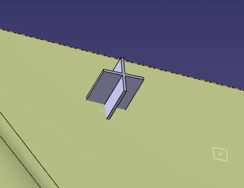
The next step is to give the draft.Here the draft shoulbe be given about the 0.5 degree and select the base as the Neutral element.Give the entry chamfer about 1 mm and the all face fillets upto 0.3mm.
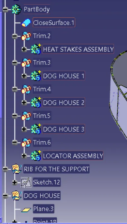
After creating the one locator it should be replicate too.For that copy the Geometrical set of the 4 way locator and paste it in the Main Body.So,new copied partbody will be formed in the tree structure.Then we have to paste it in the required place by translation method by adjusting the cordinates.
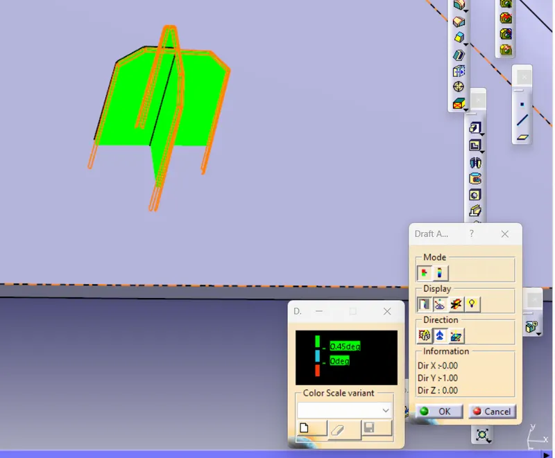
The above figure shows the draft analysis of the 4 way locator.
Next we have to create is the Heat Stakes.For creating the heat stakes,make points in the component wherever is necessary.So, create one heat stakes and copy and paste wherever is necessary.While creating the heatstakes it should be 15mm gap adjacent to each other.
Inorder to draw the heatstakes,we are taking the outer diameter as 7 and the hole as 5.The height of the heatstakes must be lesser than the locator.Because the locator is going to fix first.The heatstakes can only be fixed only after positioning the locators.
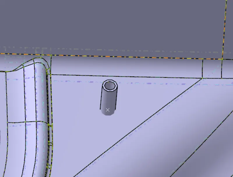
Define the heatstakes in a body.Copy this body and "paste with special" in the main body.From the window that appears select "point to point".Select the first point and the secand point.Then the heatstakes will appear in the secand point.Repeat this step for all the points.
Draw the ribs for the heat stakes for the supporting function.
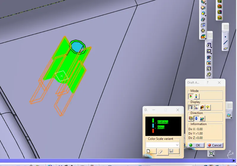
The above figure shows the Draft analysis of the heatstakes.
The next feature we have to draw is the doghouse.
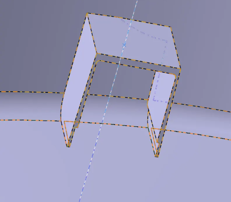
The height of the dog house is taken as the 30mm and thickness is taken as the 2.5mm.The profile of the doghouse is drawn in the part workbench.First pad the sketch of 30mm width and the 30mm height.After perform the shell option.Draft with 1.45 degree for the outside.After thet draw the sidecore.For drawing the sidecore,take the height as the 4mm.Then create a sidecore axis.Draft 0.5 degree the innersides withrespect to the sidecore axis.