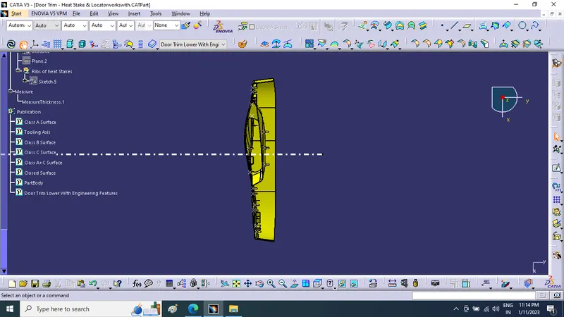
Week 9 - Project 1 - Door Trim Lower with Engineering Features
Aim : Week 9 - Project 1 - Door Trim Lower with Engineering Features
Create the Door Trim Lower Plastic component through the given Class-A surface. To begin with, the tooling axis for the given Class-A Surface should be created meeting the requirements of the draft angle and at the end perform the Draft analysis on the model.
Create the Heat Stakes and the locators considering the design rules mentioned in the video for the door applique.
NOTE:
- Sketches
- Use Positioned sketch
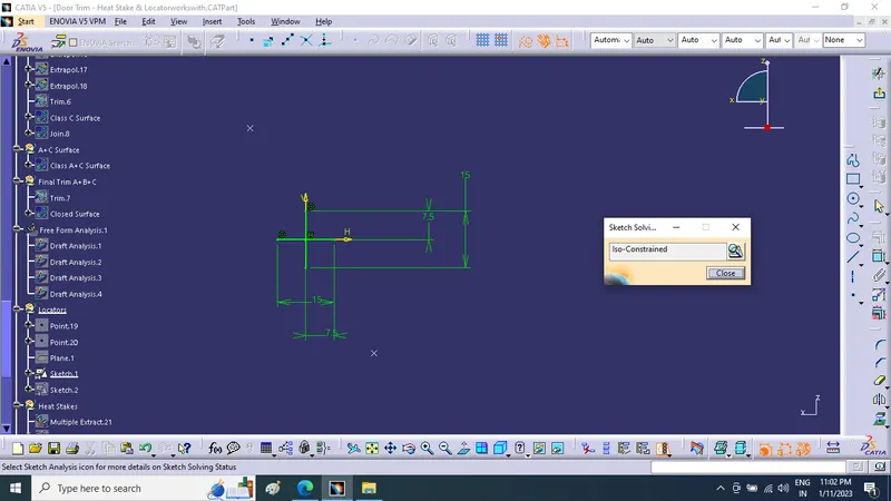
- Sketches should be Iso-Constrained
- References
- Use the given points in the model to create the locators and Heat stakes
- Refer to the below-given image for more details
- Tree Structure
- Ensure Proper Tree Structure
- Geometrical sets should have a proper name based on the sketches present inside of it
- All the sketches should be created under the Geometrical set
- Report
- A detailed report should be done explaining the draft analysis and the tooling axis creation.
- An explanation should be given on the way of creating the tooling axis, particularly the Bisecting method.
- Submission in challenge box
- Screenshots of the completed design in various orientations (Isometric, Front, Side, and Top View)
- Below images/screenshots should be inserted into the challenge box
- Submission as an attachment
- CATpart should be submitted as an attachment using the below Browse option.
Objective:Create the Door Trim Lower Plastic component through the given Class-A surface. To begin with, the tooling axis for the given Class-A Surface should be created meeting the requirements of the draft angle and at the end perform the Draft analysis on the model. Create the Heat Stakes and the locators considering the design rules mentioned in the video for the door applique.
Description:
Initially, we need to offset the given Door Trim class A surface in the inner direction to the required thickness (here the thickness is 2.5mm). After that, we need to close the patches on the offset surface of the bumper, the patches are formed due to the fillets on the Class A surface. Once all the patches are closed properly join them together to make a proper class B surface and now sweep the boundary of the class A surface to trim with the class B surface to make a closed body. By using the closed body command in the Prat workbench we can get the solid body from the closed surface of the Door Trim. Now, created the Heat stakes and Locators by considering all the design parameters.The main aim of this challenge is to create a solid body of 'Door Trim Lower' with the help of the closed surface method by using the 'Generative shape design'. Performing the 'Draft Analysis' on the solid part body of the Door trim. After creating all the B-side features on the solid part body of the door trim, performed a draft analysis for it to check whether all the surfaces are drafted properly or not (The draft angle for the plastic component is 0.5deg to 3deg).
TOOLING AXIS:
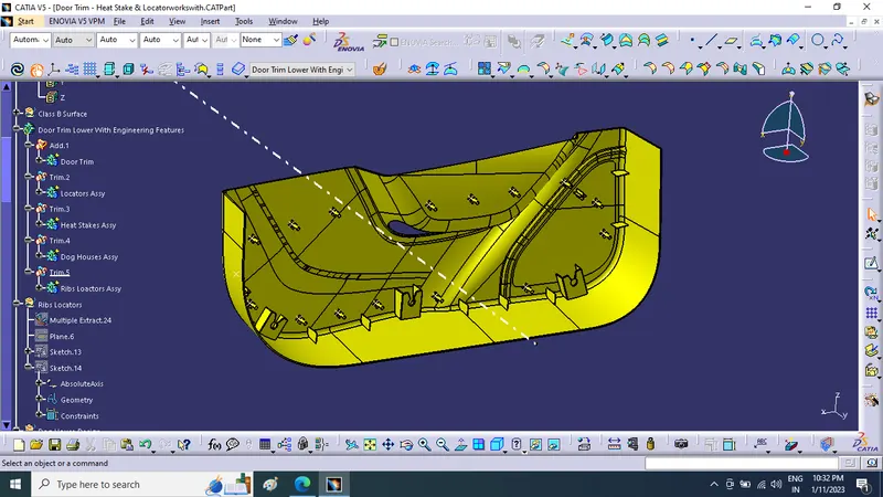
To create the tooling axis, extracted a surface from class A and created a point in the middle of the surface by using the point command and created a line at that point through the x-axis. Now, performed a draft analysis check from that line whether the created tooling axis is in the correct position or not. If in the draft, analysis check the surface highlighted with green colour on both sides of the surface the tooling axis is in the correct position and direction.
Tooling axis:
DRAFT ANALYSIS FOR CLASS A SURFACE:
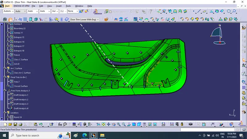
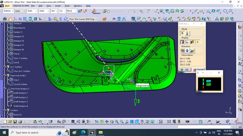
We do perform the draft analysis check for class A surface before we make solid and creation of B-side features. Initially align the compass to the tooling axis and gave a 3deg draft angle for the green colour in the colour bar. If the surface is highlighted in green colour the draft angle is given properly for class A surface. If the class A surface is not highlighted fully in green colour, that might be the reason for the draft angle of the class A surface.
CLASS B SURFACE:
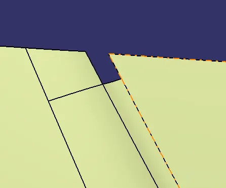
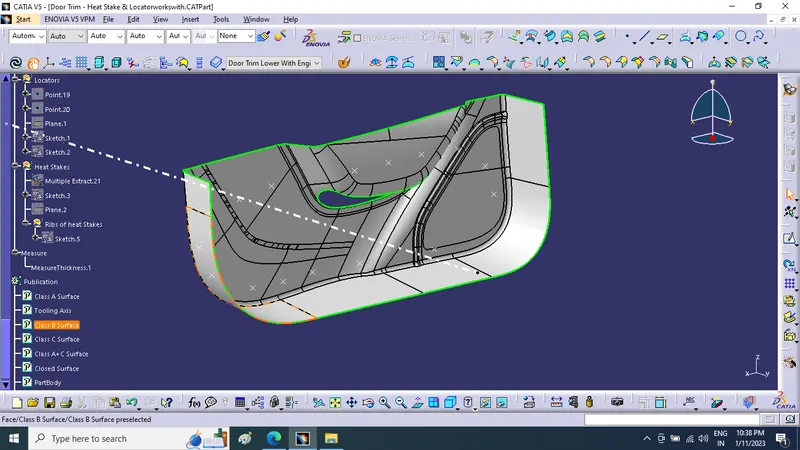
To create the class B surface, offset the class A surface inside as per our thickness requirement (here the thickness is 2.5mm, so I offset the class A to 2.5mm inside). Once the offset is created, we can observe some patches on the offset surface by taking the boundary for the offset surface, those patches are formed due to the fillets on the class A surface. We need to cover those patches with the help of the multi-section surfaces command by extracting the patch boundaries. Once all the patches on the offset are covered properly join all the patches with the offset surface, to get the replicated surface of the class A surface.
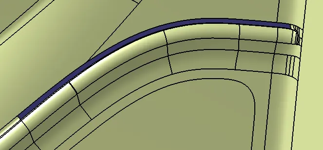
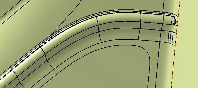
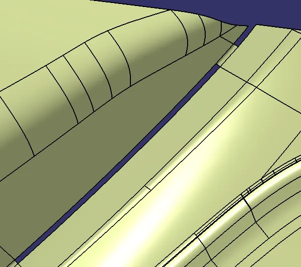
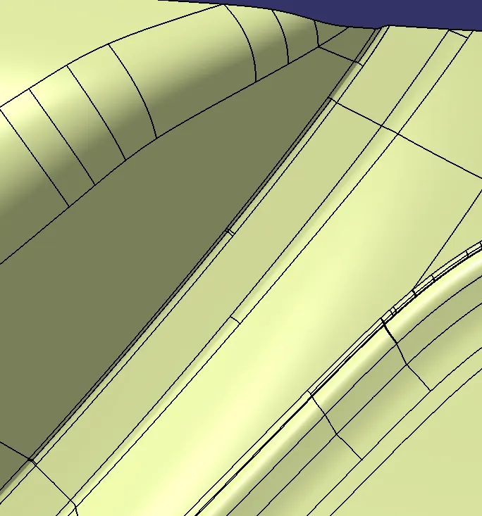
Class B Surface:
CLASS C SURFACE:
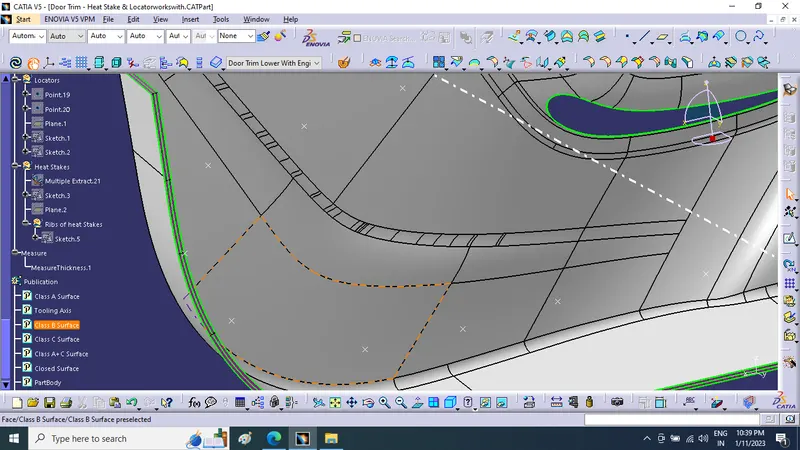
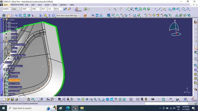
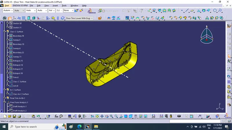
I used the sweep command to create the class C surface concerning the boundary of the class A surface. Initially, I extracted the boundary of the class A surface with tangent continuity, and I sweep the extracted boundary concerning the surface at 93deg (for draft angle) for 4mm to intersect properly with the class B surface. Once we sweep all the surface boundaries of class A, extrapolate the sweeped surfaces until both surfaces got intersect properly, and trim them to remove extended extrapolated surfaces to get a proper sweep boundary throughout the entire surface, including the centre hole of the door trim. Now, join both class A and sweep boundary to get the complete class C surface.
Class C surface:
Class A+C:
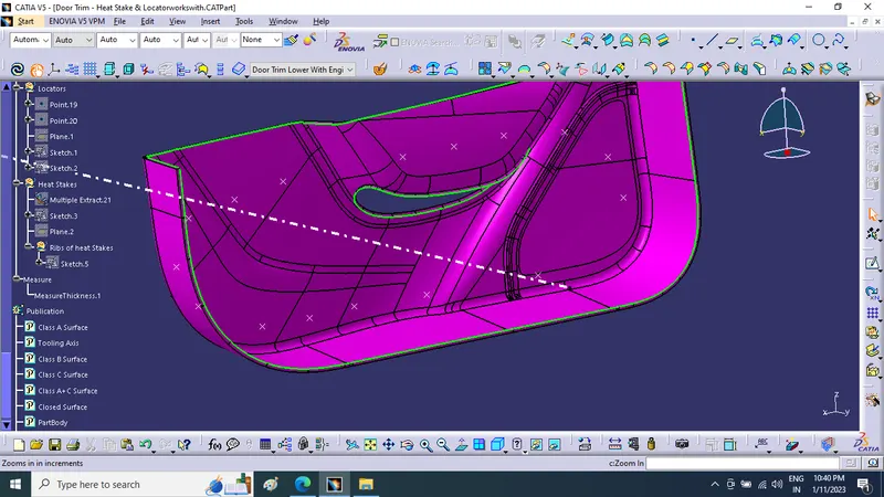
Now, unhide the class B and class C surfaces. Check whether all the sides of class B and Class C surfaces are intersecting properly with each other, to get a closed surface by trimming class B and class C surfaces. If the class B and class C sides are not intersected properly, we need to extrapolate the sides of the class B surface which are not intersecting with the class C surface. Now, check class B and class C surface boundaries to see whether all the sides are intersecting or not with each other. Once the surfaces are intersecting properly trim them together to get a closed surface.
Closed Body & PART BODY:
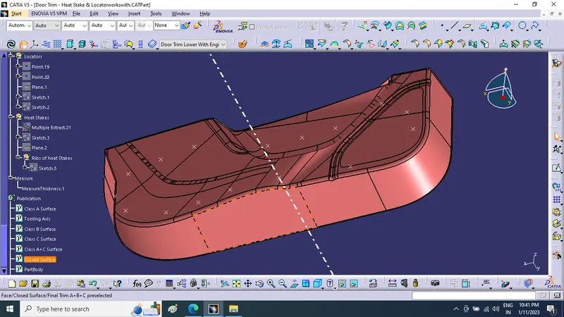
To create the solid part body from the closed surface, I used the closed surface command in the part workbench Solid part body:
CREATION OF LOCATORS:
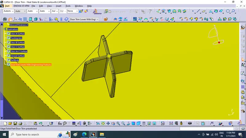
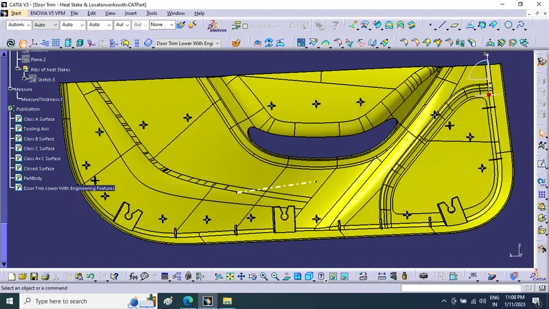
To create the locators, created a sketch on the body. After creating the sketch, pad it 22.5mm in height and thicken it to 1.4mm and I drafted it with 0.5deg in the direction of the tooling axis. I gave 2mm of chamfer with 45deg of inclination and after I gave a fillet of 0.3mm radius.
4-way locator:
CREATION OF HEAT STAKES:
To create the heat stakes .draw a sketch on the surface. After the creation of the sketch, pad it gave a draft angle of 0.5deg on both sides , draw a sketch and pad it to height and 1.4 mm in thickness. After padding the ribs, drafted 0.5deg in the tooling asix direction and filleted it with a radius. Finally, I union trim the ribs with a heat stake to remove the ribs, which are present inside the heat stakes.
Heat stake sketch:
Heat stake supporting rib sketch:
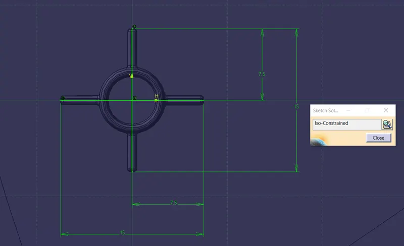
Heat stake with supporting ribs:
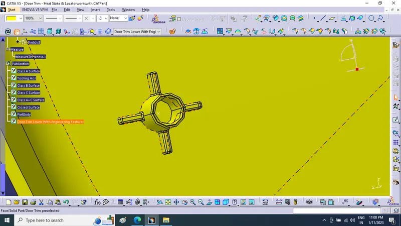
Now translated the heat stakes by copy-pasting them in the part body according to the requirement.
Final part body with 4-way and 4way locators including all the heat stakes with supporting ribs:
- Tree Structure
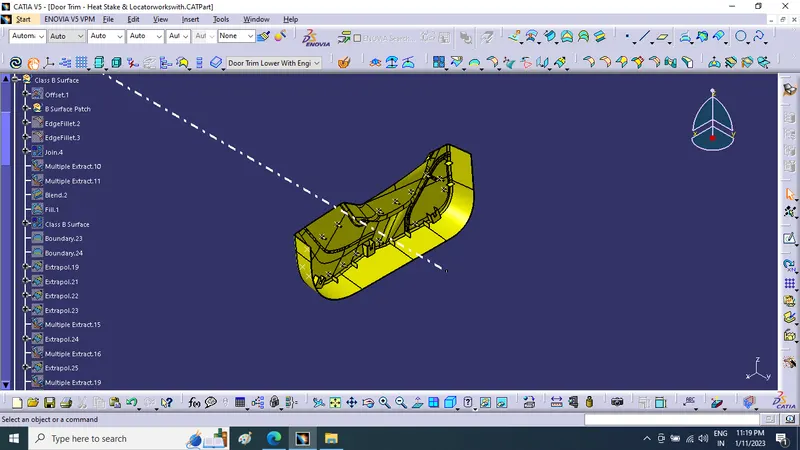
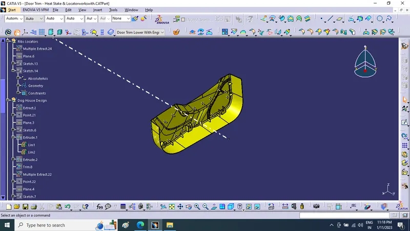
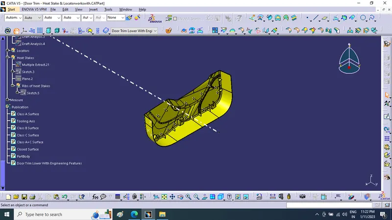
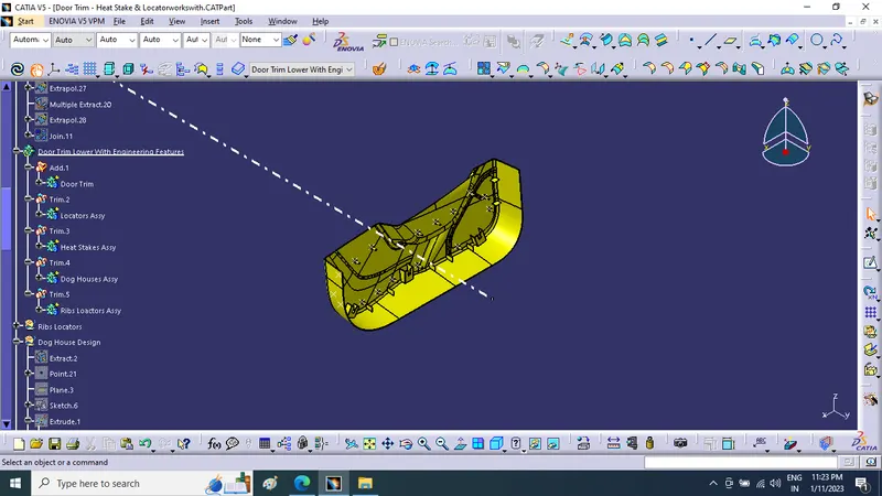
Geometrical Sets Tree Structure
Class A & Tooling axis
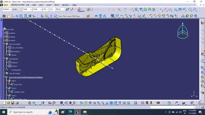
Class B
class C
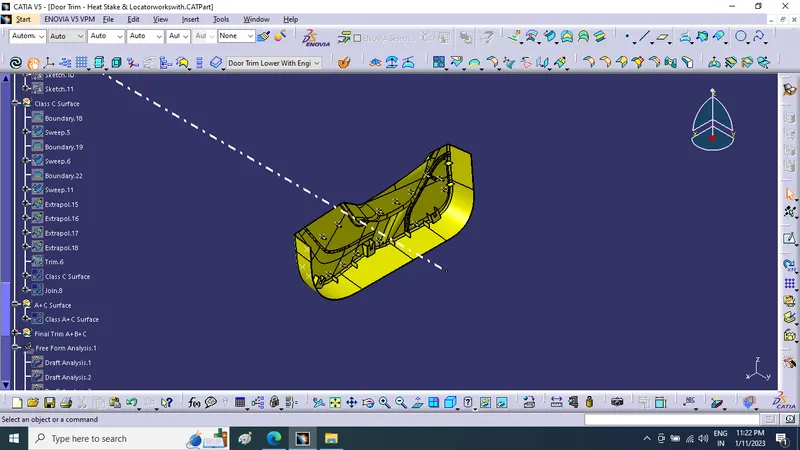
final Trim Draft analysis
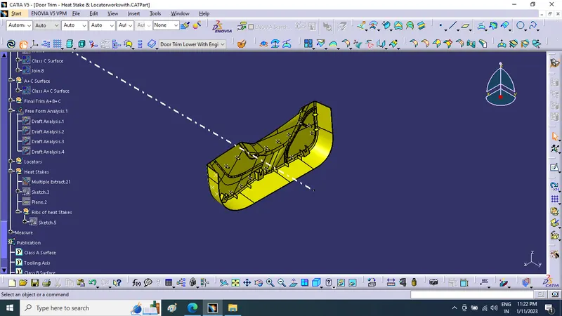
Publication
Part Tree Structure
DRAFT ANALYSIS FOR PART BODY:
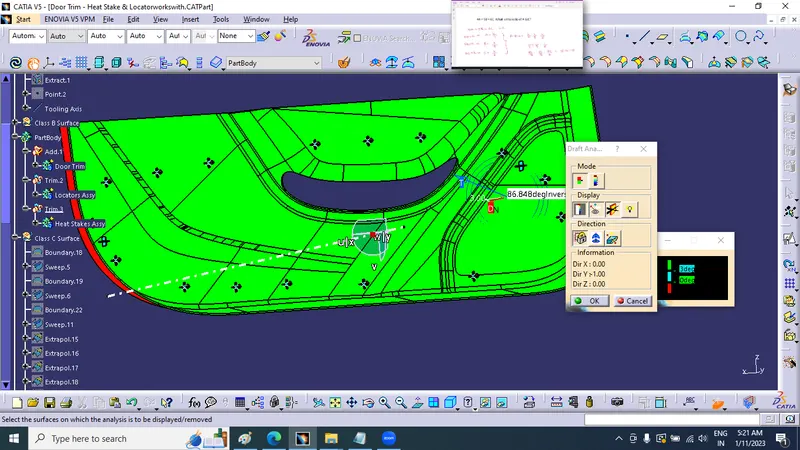
Some faces are not cleared properly, this is due to the curvature and inclinations on the class A surface.
The below-given images visualize the surfaces which are not cleared properly with a 3deg draft angle.The below-given image is mostly tilted toward the class A side, which is the reason for the highlighting in green colour.
Draft analysis for Heat stakes and Locators:
The draft angle for heat stakes and locators is 0.5deg
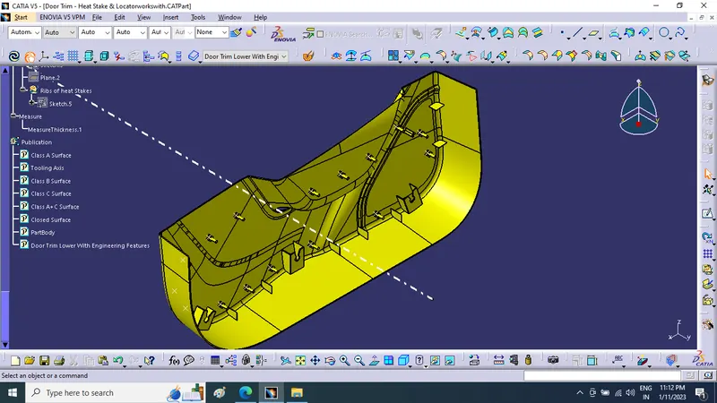
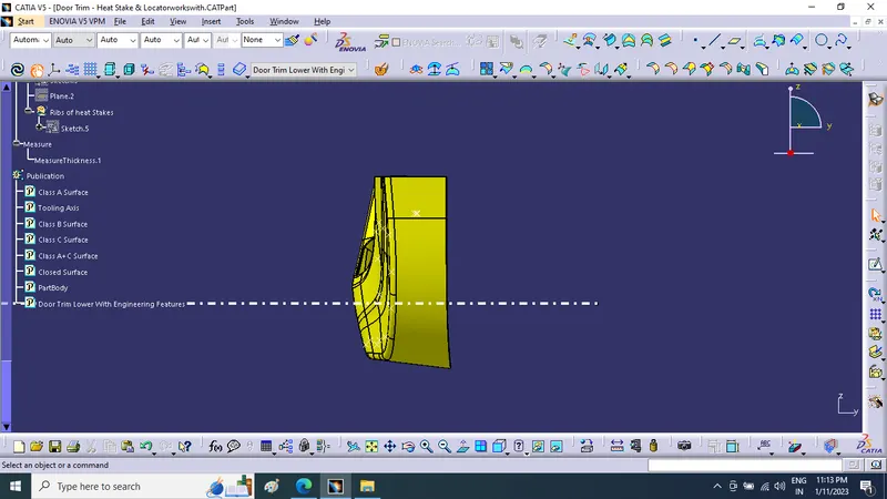
- Screenshots of the completed design in various orientations (Isometric, Front, Side, and Top View)
Isometric view:
Front view:
Right side view:
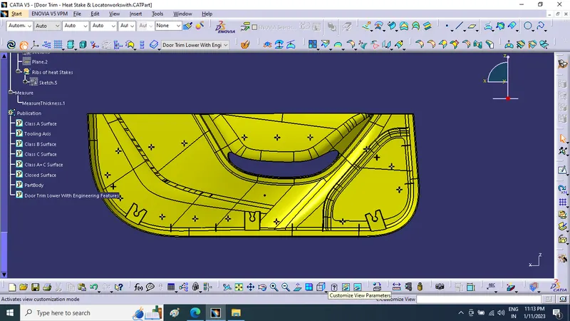
Top view: