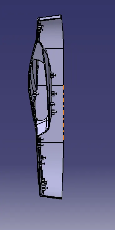
Week 9 - Project 1 - Door Trim Lower with Engineering Features
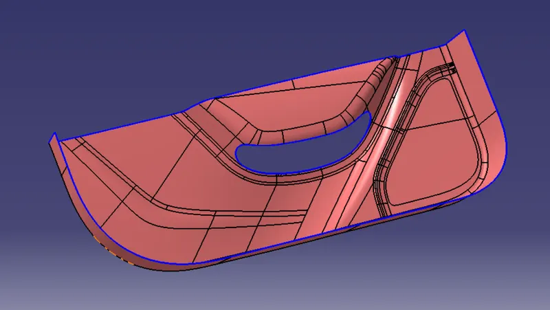
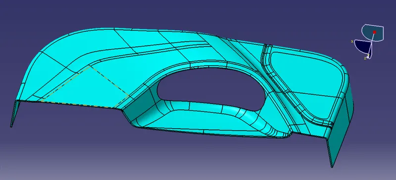
STEP 1: DOWNLOAD THE GIVEN DOOR APPLIQUE CAT PART
- Simply downloading the given CAT Part which is a CLASS A SURFACE for us.
- Class A surface is an aesthetic or styling surface that you can get from the styling team. We will incorporate the Class A surface into the plastic component design.
- The connectivity of the class A surface that has no gaps between its components can be verified using the join or boundary commands.
STEP 2: CREATION OF TOOLING AXIS
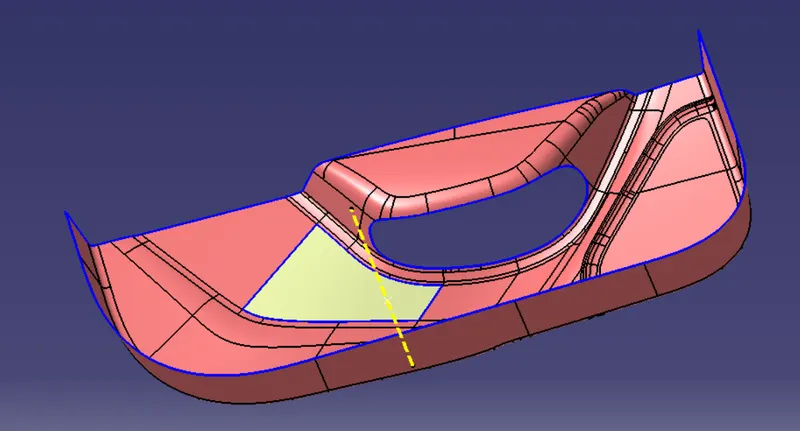
- The axis would be the tooling direction since it makes manufacturing very simple and allows all faces and the complete surface to be covered without the need for additional equipment.
- Visually checking in every direction i.e x, y, and z direction so that the tooling axis clearly clears all surfaces.
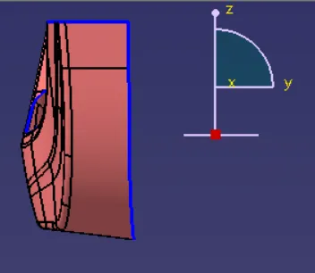
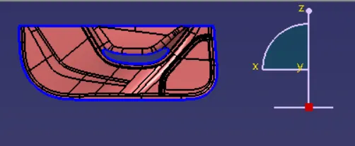
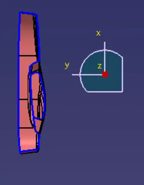
- So by checking, we get that the y direction is the best direction for creating the tooling axis.
- The simple procedure for creating a tooling axis is to extract a surface and create a point over it and simply draw a line over it in the Y direction.
STEP 3: CREATION OF CLASS B SURFACE
Engineering features are to be created by the class B surface, which will offset the class A surface. First, we'll extract surfaces from the class A surface using the extract command. Finally, we must create a smooth surface if there are any patches in order to obtain the entire boundary.
OFFSET CLASS A SURFACE
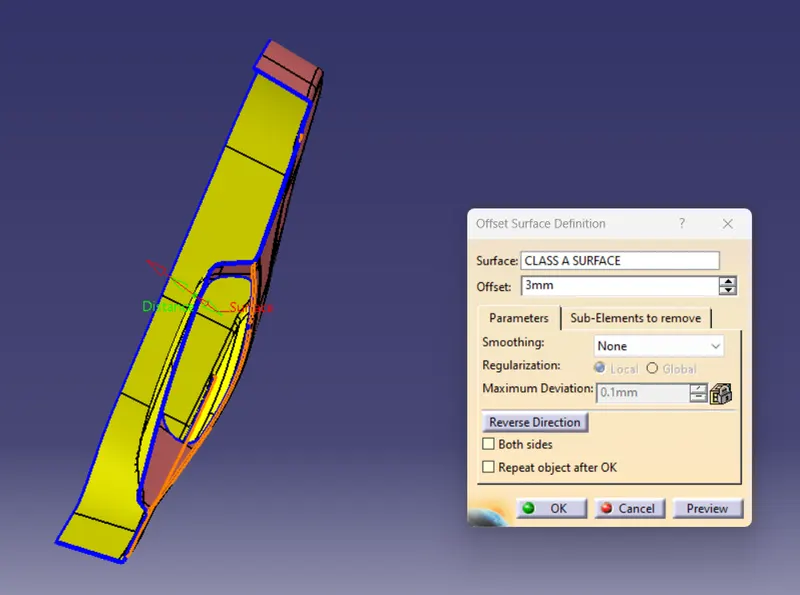
USE MULTIPLE EXTRACT COMMAND AND EXTRACT SURFACE
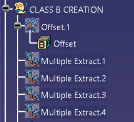
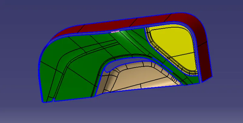
USING EXTRAPOLATE COMMAND AND MULTISECTION COMMAND TO FILL THE GAPS AND GET A FINAL CLASS B SURFACE
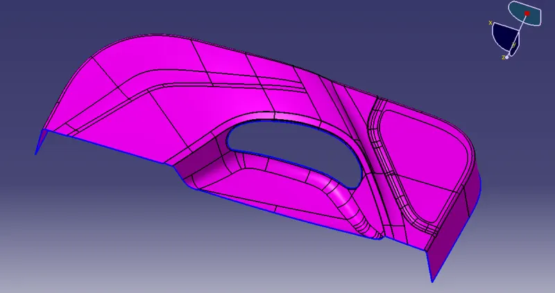
STEP 4: CREATION OF CLASS C SURFACE
- Class A and Class B are connected by the Class C surface, so we must use the boundary command to establish the component's whole border for this surface.
- To create a class c surface we use sweep, extrapolate, multisection, join and trim commands.
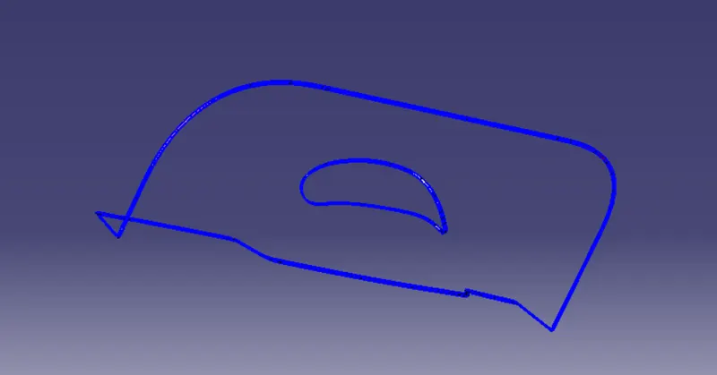
STEP 5: FINAL JOIN AND TRIM
JOIN A & C
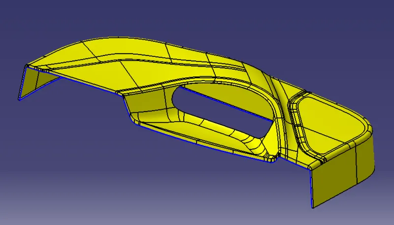
FINAL SURFACE
CREATION OF 4 WAY LOCATOR
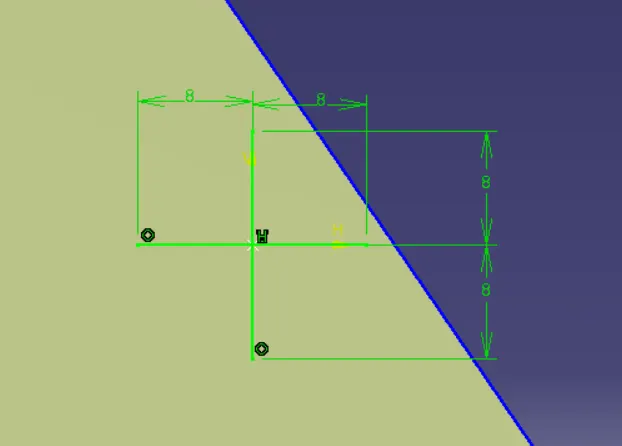
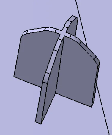
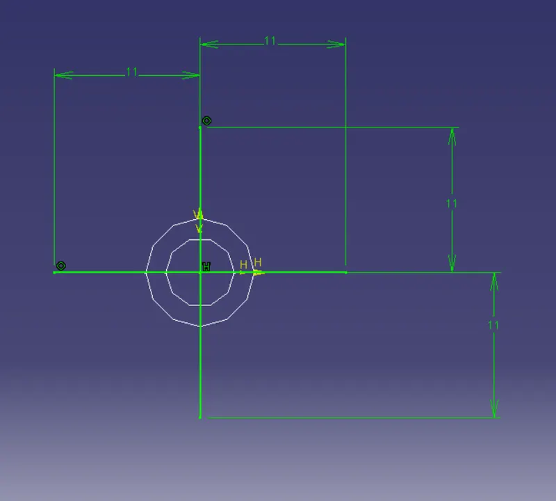
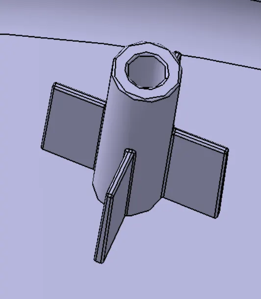
Make a sketch of the body to use as the basis for the locators. After making the sketch, I gave it some height, made it thicker, and drew a 0.5-degree angle in the tooling axis direction. I applied a 5mm chamfer at a 45deg angle, followed by a 0.25mm radius fillet.
CREATION OF HEAT STAKES
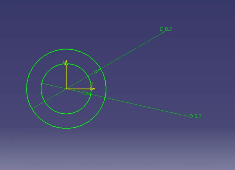
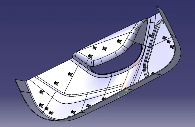
In the automobile industry, heat stakes are most frequently used to fuse plastic to various substrates. To grab or lock another material, such as plastic or metal components, heat staking is an assembly technique that allows control over the melting and reformation of plastic bosses or studs.
FINAL DOOR TRIM WITH HEAT STAKES AND LOCATORS
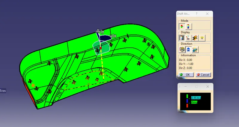
DRAFT ANALYSIS
DRAFT ANALYSIS OF CLASS A SURFACE
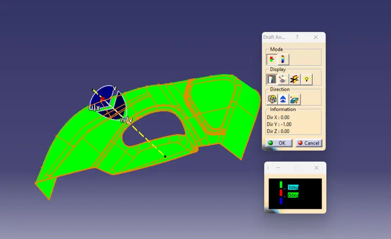
DRAFT ANALYSIS OF CLOSED SURFACE WITH HEAT STAKES AND LOCATORS
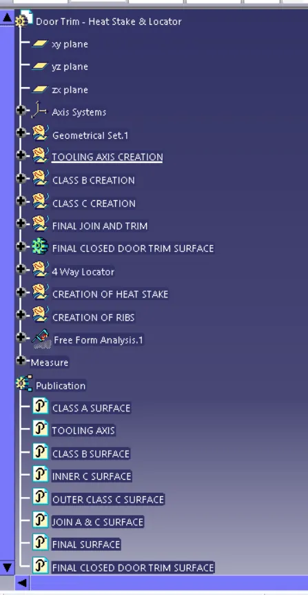
TREE STRUCTURE
Screenshots of the completed design in various orientations (Isometric, Front, Side, and Top View)
ISOMETRIC VIEW
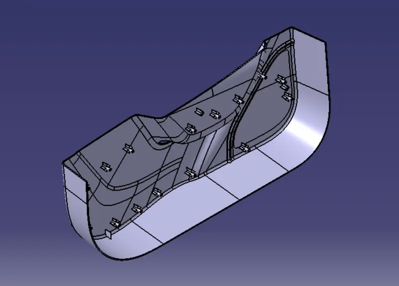
FRONT VIEW
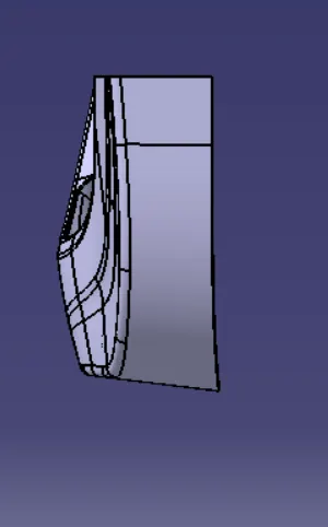
SIDE VIEW
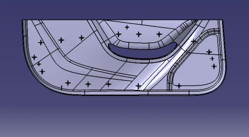
TOP VIEW