Week 9 - Project 1 - Door Trim Lower with Engineering Features
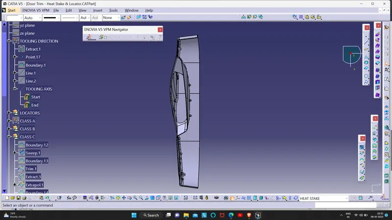
AIM : To Create the Door Trim Lower Plastic component through the given Class-A surface and to Create the Heat Stakes and the locators considering the design rules mentioned for the door applique.
An explanation should be given on the way of creating the tooling axis :
To create the tooling axis, I extracted a surface from class A and created a point in the middle of the surface by using the point command and created a line at that point through the x-axis. Now, I performed a draft analysis check from that line whether the created tooling axis is in the correct position or not. If in the draft, analysis check the surface highlighted with green colour on both sides of the surface the tooling axis is in the correct position and direction.
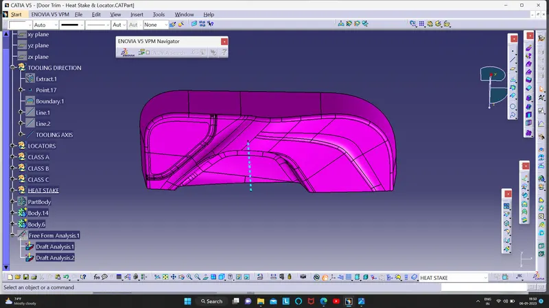
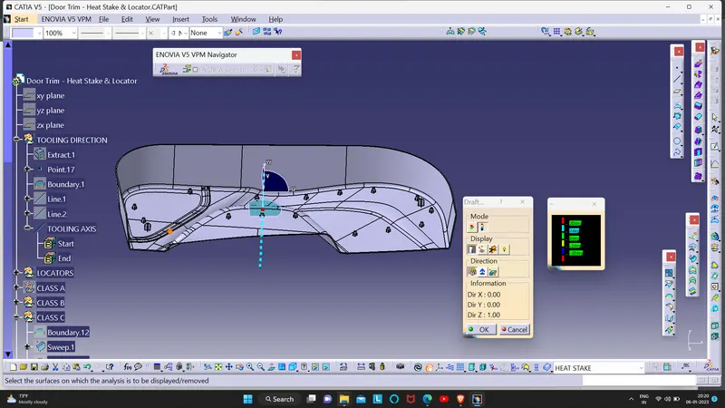
A detailed report should be done explaining the draft analysis :
- Follow the steps : Go to insert> analysis> feature draft analysis
- Place the compass on the Tooling axis that is created using bisecting method .
- Select the lock symbol to fix compass along with tooling axis .
- Click on the surface then various Color codes will be appeared and Draft angle is applied . Make sure that the surface is within the permissible limit of the draft values. The surface should be green and nominal draft value should be 3deg .
- Thus the draft analysis on the class-A surface is successfully performed.This is our required Tooling axis
CLASS B SUFACE:
To create the class B surface, offset the class A surface inside as per our thickness requirement (here the thickness is 2.5mm, so I offset the class A to 2.5mm inside). Once the offset is created, we can observe some patches on the offset surface by taking the boundary for the offset surface, those patches are formed due to the fillets on the class A surface. We need to cover those patches with the help of the multi-section surfaces command by extracting the patch boundaries. Once all the patches on the offset are covered properly join all the patches with the offset surface, to get the replicated surface of the class A surface.
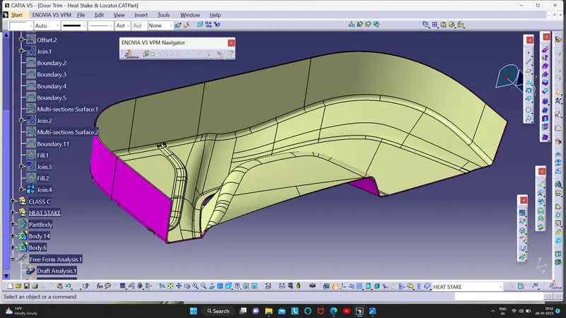
CLASS C SURFACE:
I used the sweep command to create the class C surface concerning the boundary of the class A surface. Initially, I extracted the boundary of the class A surface with tangent continuity, and I sweep the extracted boundary concerning the surface at 93deg (for draft angle) for 4mm to intersect properly with the class B surface. Once we sweep all the surface boundaries of class A, extrapolate the sweeped surfaces until both surfaces got intersect properly, and trim them to remove extended extrapolated surfaces to get a proper sweep boundary throughout the entire surface, including the centre hole of the door trim. Now, join both class A and sweep boundary to get the complete class C surface.
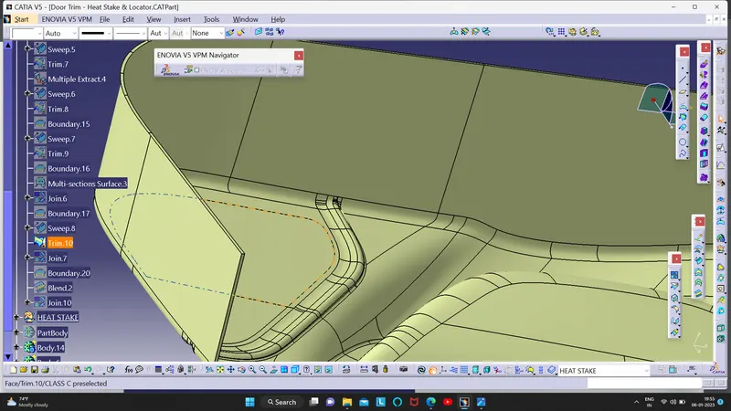
- Screenshots of the completed design in various orientations (Isometric, Front, Side, and Top View) :
ISOMETRIC VIEW :
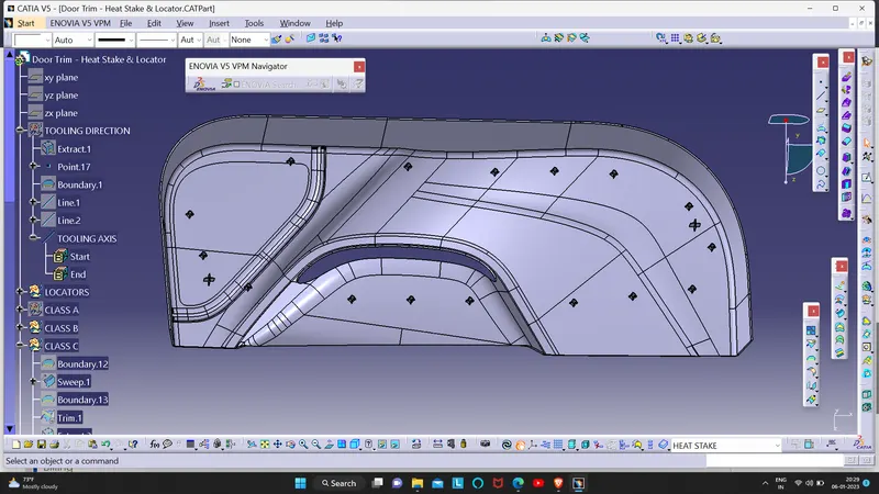
FRONT VIEW :
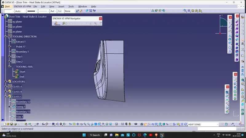
SIDE VIEW :
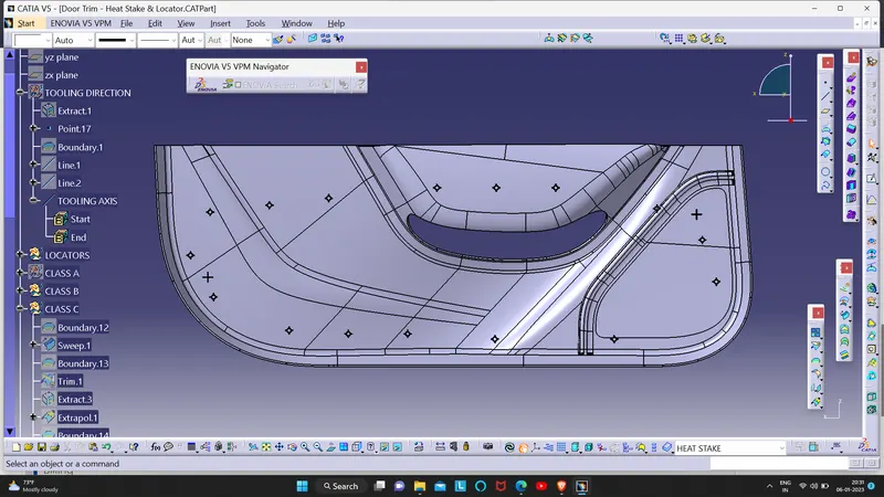
TOP VIEW :