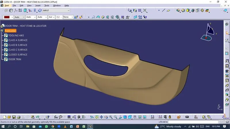
Week 9 - Project 1 - Door Trim Lower with Engineering Features
Aim
- To create the Door Trim Lower Plastic component through the given Class-A surface with the required Draft angle and perform Draft analysis on the model.
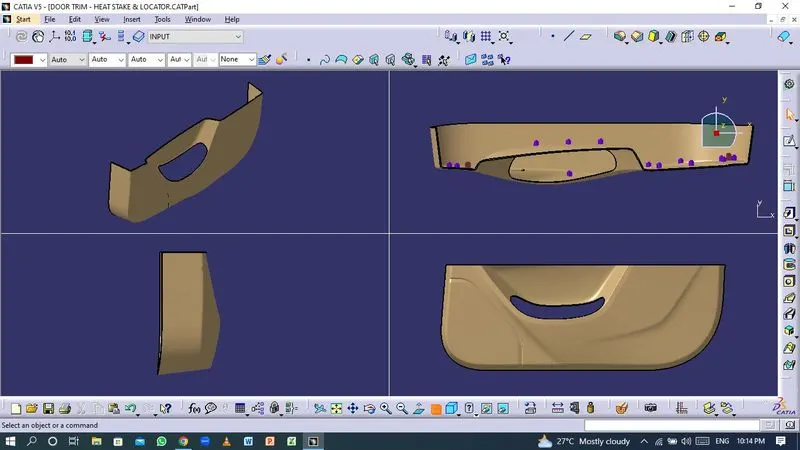
- To create the Heat Stakes and the locators considering the design rules.
Software used
- CATIA V5
Given Class-A surface
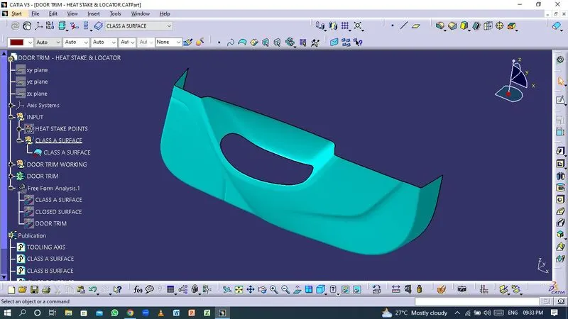
- The Class-A surface is the outermost surface of the plastic component which is also looks fine surface and it is the aesthetic surface that the designer creates as an input part for the design work.
Tooling Axis
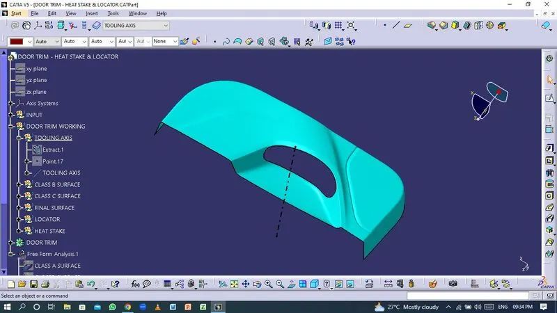
- In Molding, machine arrangement is given to open the mold along a direction which is known as Tooling Direction. In other words. The mold is built from two separate halves (Core and Cavity) and tooling direction basically defines the direction of mold or core pulls apart.
- The tooling axis is created by Bisecting method.
- Bisecting method : Using a dummy tooling axis, the bisecting approach is essentially used to identify the correct tooling axis. When using the bisecting method, a line is used to either bisect the two lines or show an error, indicating that the two lines are parallel to one another. In order to determine whether a specific surface is toolable or not, we interest the surface with the appropriate plane to produce a sketch that consist of two lines. Using the bisecting line option, we then divide the two lines, creating a line at the intersection of the two lines.
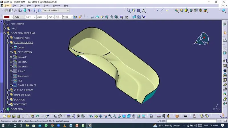
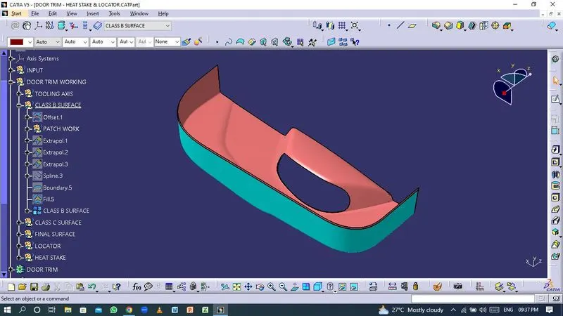
Creation of Class-B surface
- The Class-B finish is a quality finish with only minimal imperfections. A Class-B finish is the most common finish for exterior surfaces. It is normally specified on surfaces such as external covers, panels, and parts that are fairly prominent.
Creation of Class-C surface
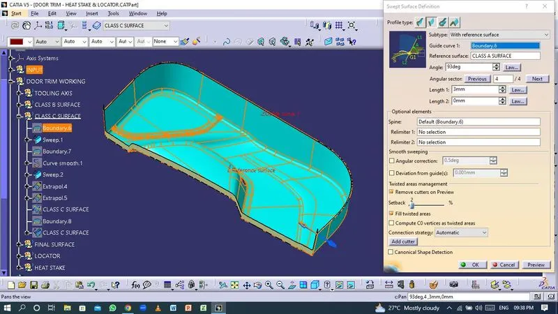
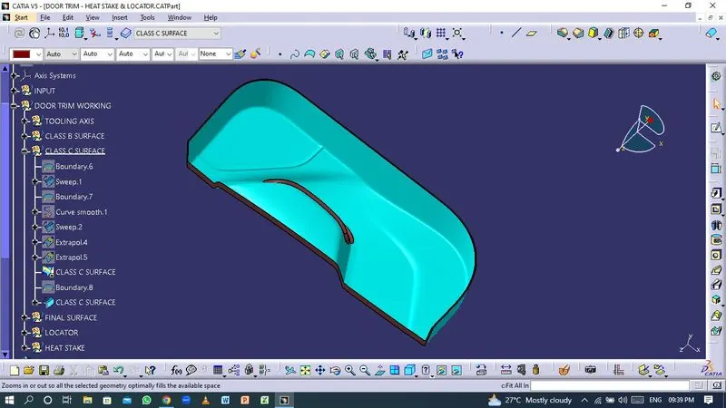
- The Class-C finish allows more imperfections than Class-A or Class-B. Class-C is often specified for interior surfaces not readily visible, surfaces that will be covered by another part when assembled, or surfaces which the Customer feels do not need to meet a high cosmetic finish.
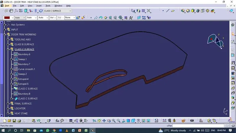
Final surface
- The Class-A, Class-B and Class-C surfaces are joined together to form a closed surface.
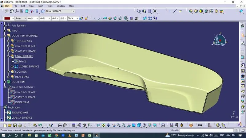
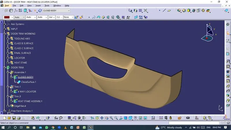
Thickness : 2.5 mm
Creation of locators
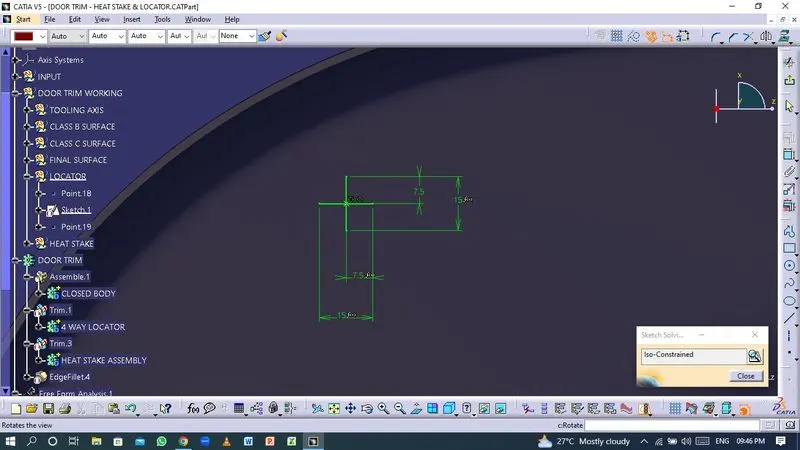
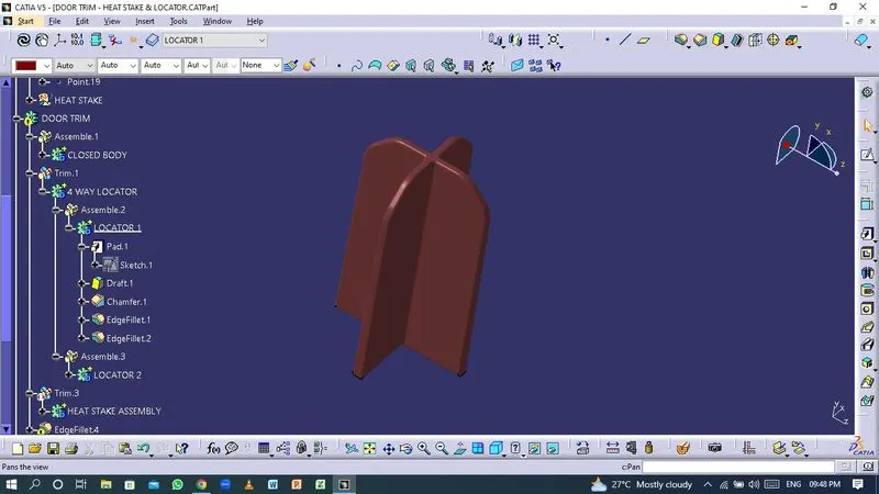
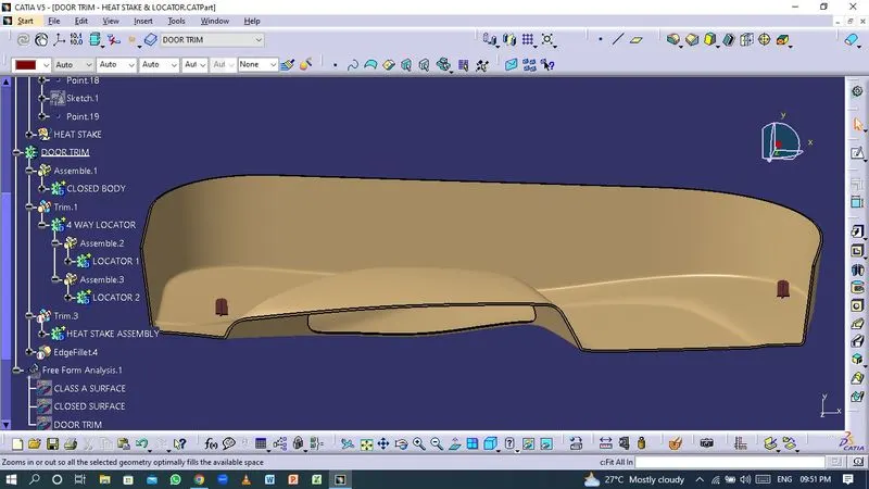
Locators are used to positioned the components in exact location and act as a guide for joining the two components.
Guidlines for Creating Locators:
- Draft : 0.5* per sides.
- Thickness - Tipically 40% wall thickness.
- Maximum fillet radius 0.25mm
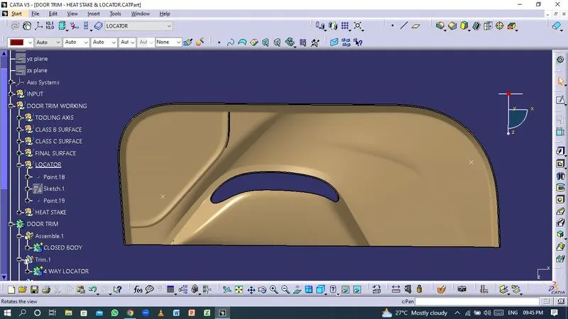
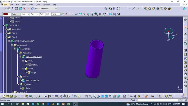
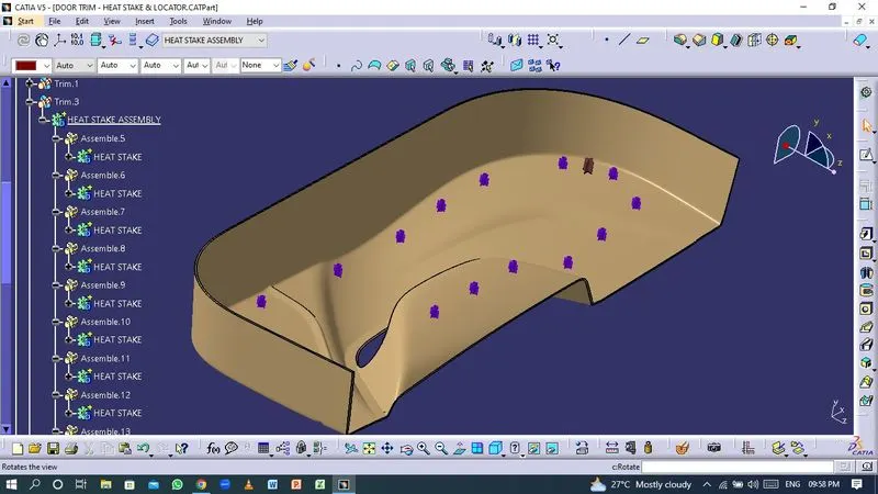
Creation of Heat Stakes
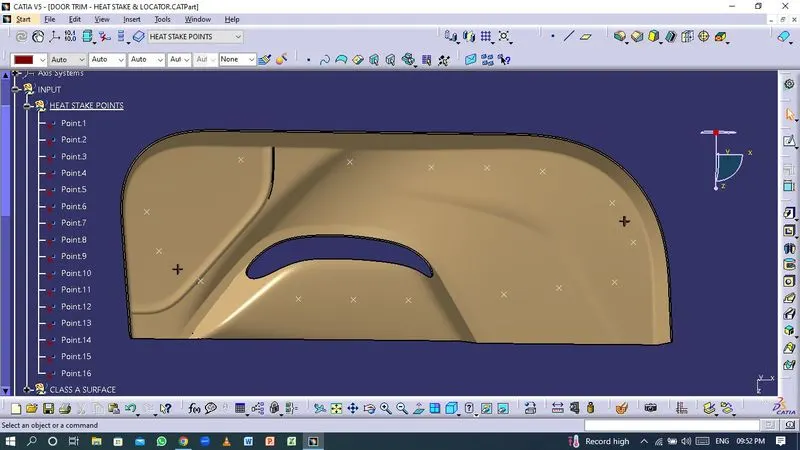
Thermal staking is an assembly method that uses the controlled melting and reforming of a plastic stud or boss to capture or lock another plastic or metal component of an assembly in place.
Guidelines for creating Heat stakes:
- Minimum 15 mmm gap between heat stakes.
- Maximun clearence with The counter clearence should be 0.5 mm
- Maximum fillet radius be 0.25 mm
- Draft : 0.5* per sides.
Draft Analysis
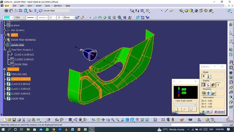
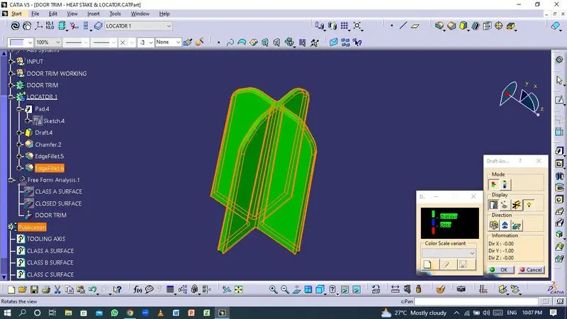
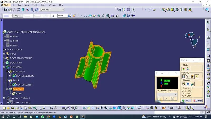
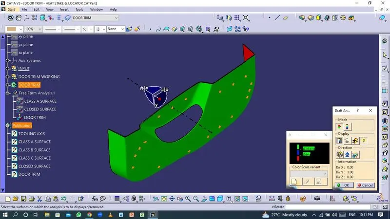
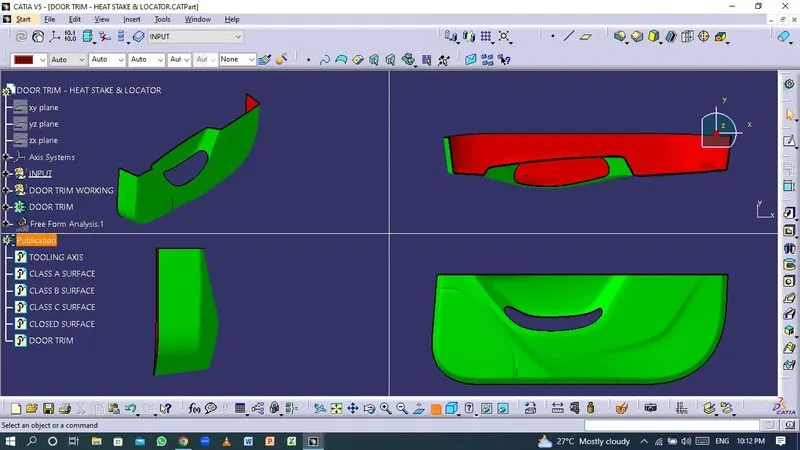
- The Draft Analysis command enables you to detect if the part you drafted will be easily removed. This type of analysis is performed based on color ranges identifying zones on the analysed element where the deviation from the draft direction at any point, corresponds to specified values.
- Most parts or applications require minimum of 1/2 to 1 degree, however 3 degrees is widely accepted as the norm.
- Draft analysis on Class-A surface.
- Draft analysis on Heat Stakes and the locators.
- Draft analysis on final component.
Conclusion
Thus the Door Trim Lower plastic component is created through the given Class-A surface using CATIA V5 software.