Fender Design - Wheel Arch Challenge
FENDER
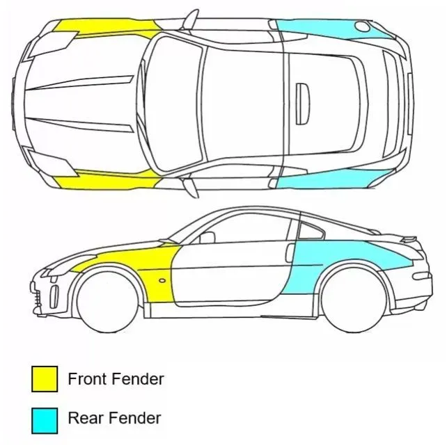
Fender is the part of a car that protects and frames its wheels and keeps mud from splashing it. Most modern vehicles have fenders on their front wheels. It is the part of a car, truck or motorcycle that surrounds the wheel sell. The primary function of a fender is to prevent dirt and debris from being thrown into the air by the rotating tire. The fender is located over the wheels of the vehicle. As such, there are four fenders on a typical vehicle: front right, front left, rear right and rear left.
WHEEL ARCH
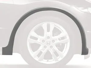
The wheel arch is the semicircular part positioned above the wheel of a vehicle. The most important body change was that the front wheel arch was cut higher into the fender. Corrosion had occurred around the splash plate at the back of the wheel arch.
TYPES OF FENDER
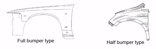
The types of fender is based upon the area covered.
- Full bumper type
Full bumper type is traditional type of fender where more material consumption is observed. This type is used in old design of automobiles where it increases the overall weight and thus reduces performance. The maintenance also relatively more due to more surface.
- Half bumper type
Half bumper type is modern design where less material consumption is observed, so productivity increases by reducing size of blank and thus providing more performance. The maintenance also relatively low compared to full bumper type.
FENDER WHEEL ARCH REGULATIONS
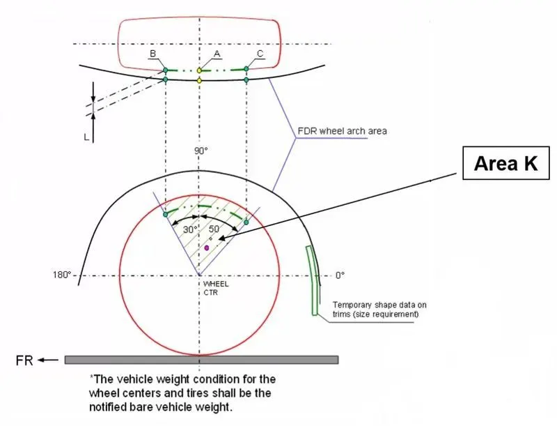
(1) Japan Regulations Requirements
- The clearance ‘L’ for tire, hub, cap and fender in three different positions within area K and produce clearance check chart to validate.
- The value of clearence 'L' must be greater than 5mm at all positions.
- Wheel guard requirement: The value of ‘a’ should be more than 5mm at line 30° forward and 50° rearwards from the central vertical axis of the wheel.
(2) US Regulations Requirements
- Clearance is to be checked at all positions from -100° to 100° and make clearance check chart to validate.
- The value of clearence should be greater than 5mm to satisfy the regulations.
- Wheel guard requirement: The value of ‘a’ should be more than 5mm at line 30° forward and 50° rearwards from the central vertical axis of the wheel.
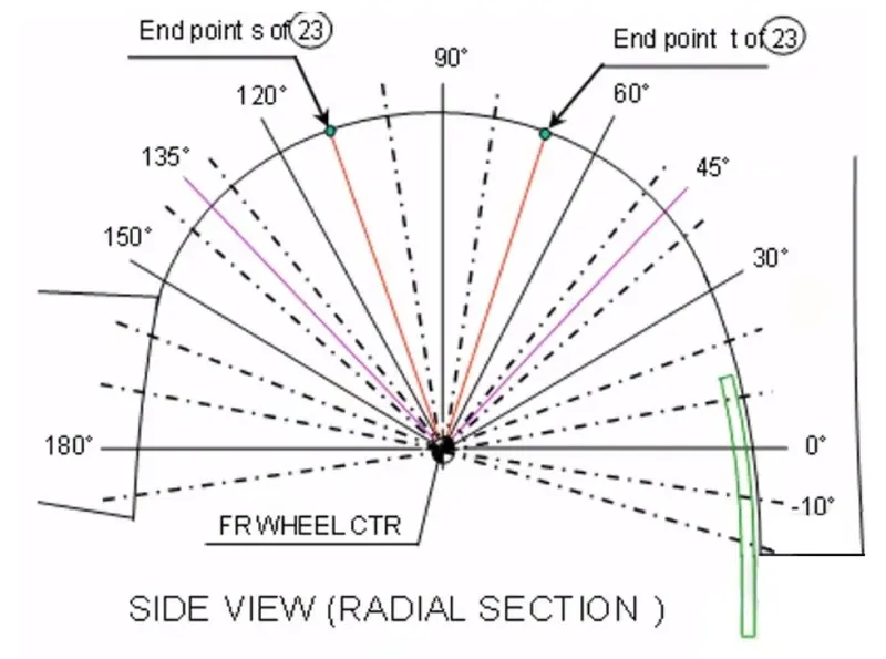
(3) European Regulations Requirements
- The Clearance ‘L’ should be measured at sections SA-SA, SB-SB, SC-SC, SD-SD and SE-SE and create clearance check chart to validate.
- At all the five sections the value of L should be greater than 10mm to satisfy the European Regulations.
- Wheel guard requirement: The value of ‘a’ should be more than 5mm at line 30° forward and 50° rearwards from the central vertical axis of the wheel.
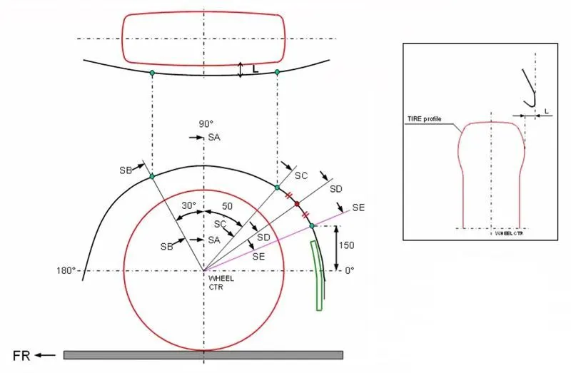
CALCULATION OF WHEEL ARCH GAP ACCORDING TO EUROPEAN STANDARD
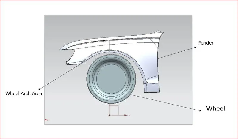
The part is opened in NX CAD. The steps are as follows.
- A Datum Plane is created at the outermost face of the wheel and the sketch is created on the same plane.
- A Horizontal line is drawn across the centre of the wheel.
- A perpendicular line SA is drawn at the centre of the wheel.
- Two lines SB and SC are created at 30° forward and 50° rearward of SA respectively.
- A point is created 150mm vertically above the centre line.
- A line SE is drawn from the wheel centre that passes through the point created.
- Another line SD is drawn from the centre of the wheel at the middle of lines SC and SE
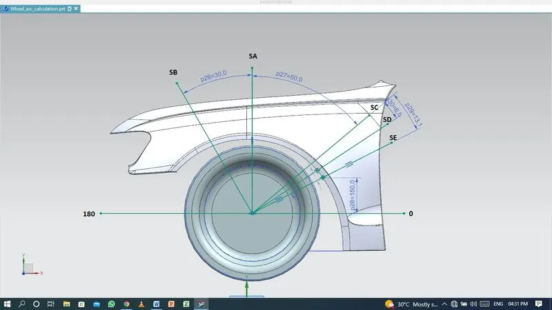
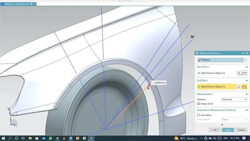
- Measure the clearence 'L' (wheel circle and fender curve) at sections SA-SA, SB-SB, SC-SC, SD-SD and SE-SE.
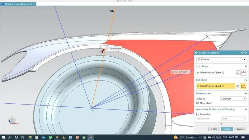
- Clearance 'L' at SA-SA
L = 9.94 mm
-
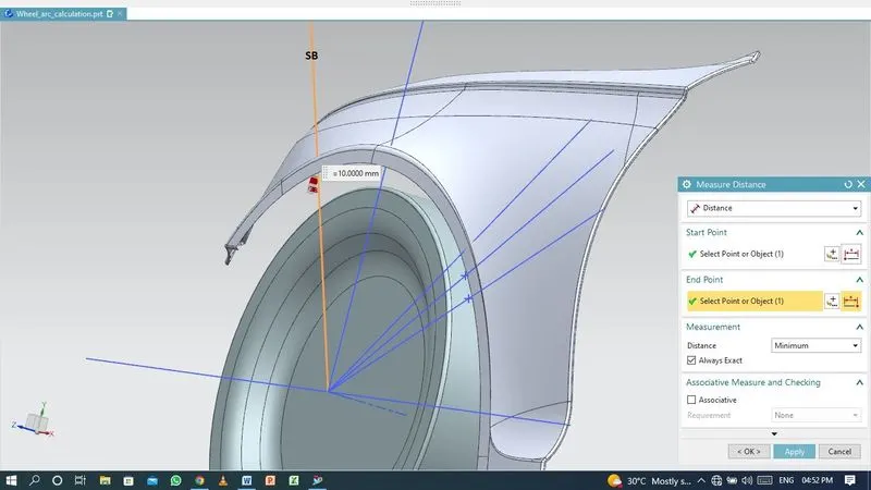
Clearance 'L' at SB-SB
L = 10.00 mm
-
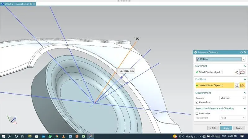
Clearance 'L' at SC-SC
L = -0.11 mm
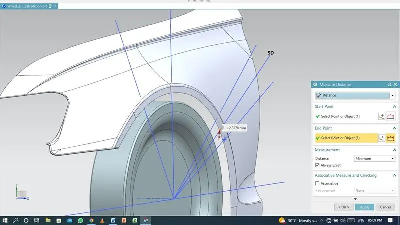
- Clearance 'L' at SD-SD
L = -2.87 mm
-
Clearance 'L' at SE-SE
L = -5.96 mm
-
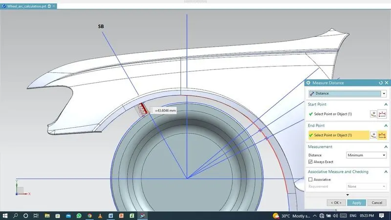
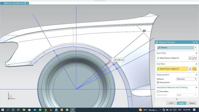
Measure the clearance vlaue 'a' for Wheel Guard Requirement at section SB-SB and SC-SC.
-
Clearance 'a' at 30° line SB
a = 43.60 mm
-
Clearance 'a' at 50° line SC
a = 38.11 mm
CONCLUSION
Requirements according to European regulations,
- The value of Clearence 'L' should be greater than 10mm.
- The value of ‘a’ should be more than 5mm at line 30° forward and 50° rearwards from the central vertical axis of the wheel.
| Section | L (mm) | RESULT |
| SA-SA | 9.94 | FAIL |
| SB-SB | 10.00 | PASS |
| SC-SC | -0.11 | FAIL |
| SD-SD | -2.87 | FAIL |
| SE-SE | -5.96 | FAIL |
| Section | a (mm) | RESULT |
| SB-SB | 43.60 | PASS |
| SC-SC | 38.11 | PASS |
From the above results we can conclude that the Fender design fail to achieve the minimum gap requirement as per European Regulations. Therefore, it is recommended to modify the model according to the regulations.