Week 9 - Project 1 - Door Trim Lower with Engineering Features
AIM
Create the Door Trim Lower Plastic component through the given Class-A surface. To begin with, the tooling axis for the given Class-A Surface should be created meeting the requirements of the draft angle and at the end perform the Draft analysis on the model.
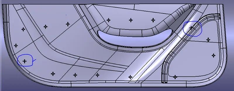
Create the Heat Stakes and the locators considering the design rules mentioned in the video for the door applique.
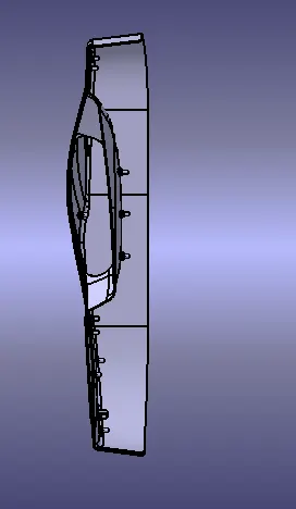
The given Class-A surface
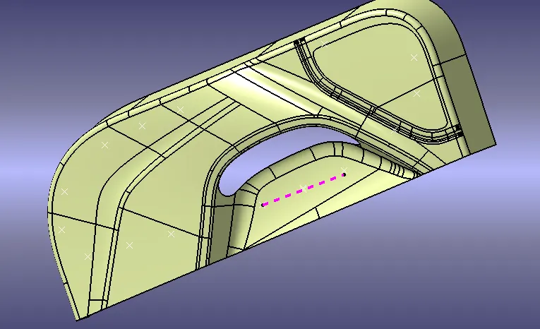
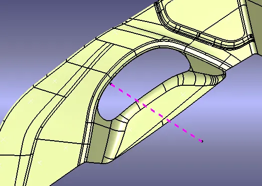
Tooling Axis
It is defined as the direction in which the mould/core and cavity open. Selection of the direction of the tooling axis depends on the ease at which components can be easily ejected.
THE CREATION OF CLASS B SURFACE
The given class A surface have complicated radius of fillet so i can used to given class A surface to be offseted with 2.5 mm and found some patchecs used to multi surface command to fix the patches
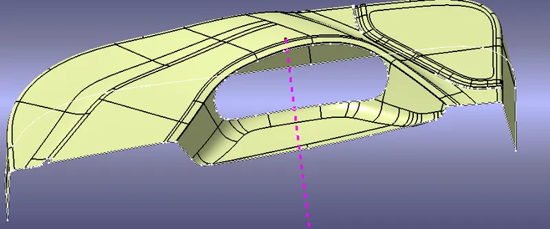
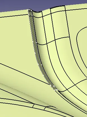
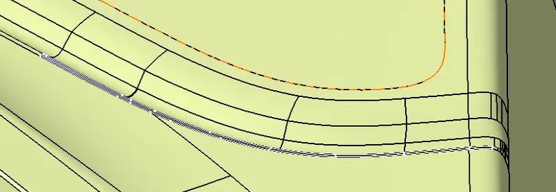
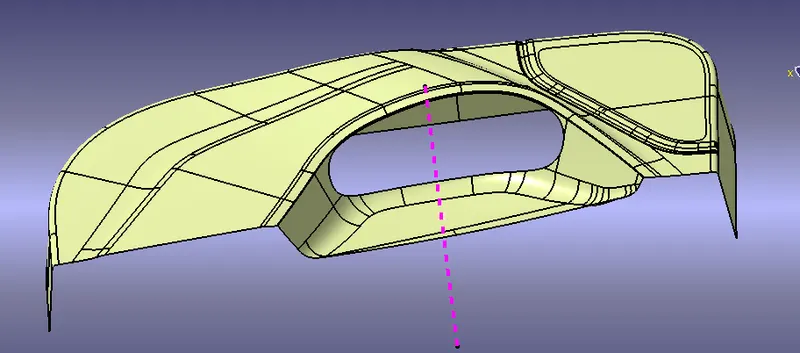
Creation Of C surface
the class C surface to be created with the help of class A and Class B surface
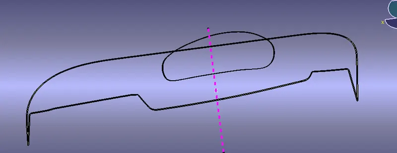
final trim
after class csurface created then join the class A ,class b and class c surfaces
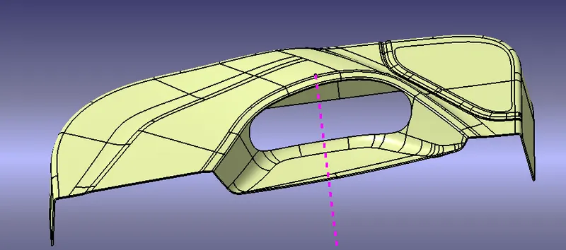
creating a closed surfaces
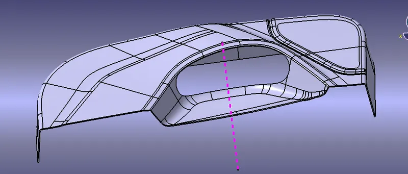
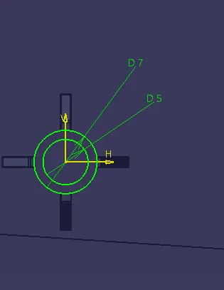
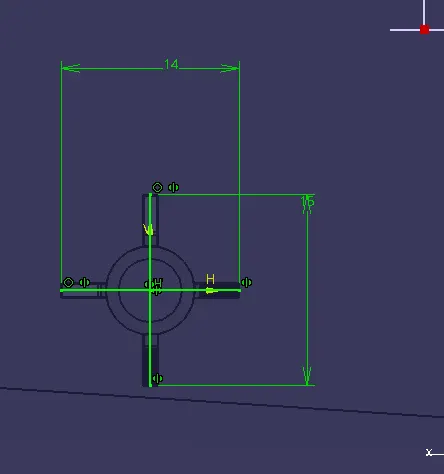
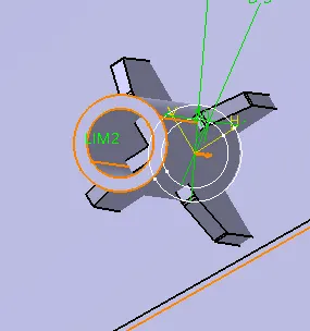
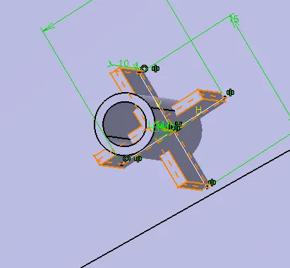
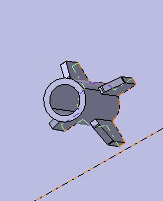
DOOR TRIM WITH LOCATORS AND HEAT STAKES
Every component in space has 12 degrees of freedom. So these locators and heat stakes restrict all these degrees of freedom.
Locators are 4-way locators. The locators will follow the rib design guidelines and will be given a minimum draft of 0.5 degrees and a minimum fillet of 0.2mm and an entry chamfer of 3mm. This entry chamfer is given so that the locators can mate with the other part easily.
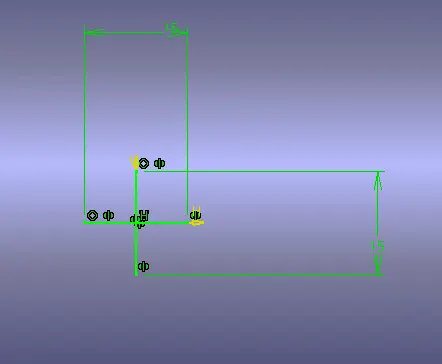
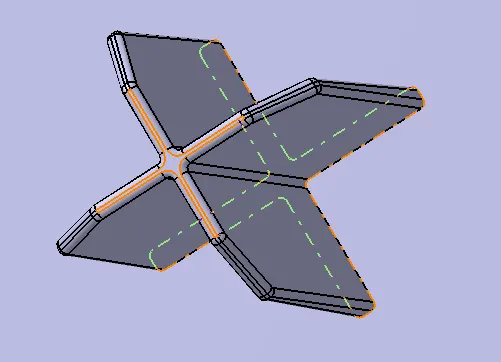
Heat stack
These heat stakes will enter the mating component and using a heat staking machine these heat stakes are melted and cooled. When cooled this will get hardened and the two components will stick together. Thus all degrees of freedom are arrested
Then, the ribs are created by following the rib design rules.
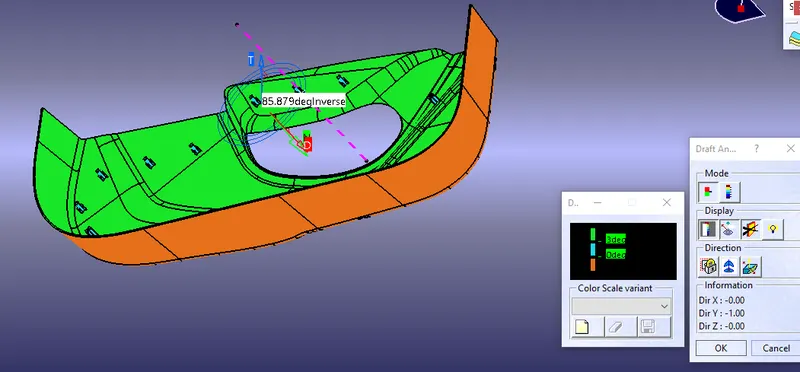
- Draft Analysis on the final component :
1. The part created has to be changed to the material mode in the display frame.
2. Compass is enabled and aligns it along with the tooling direction.
3. The lock command is then applied to fix the compass along with the tooling axis.
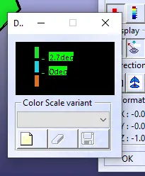
4. Color codes are classified and Draft angle is applied.
5. Running point analysis is used to display permissible draft angles.
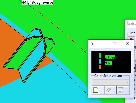
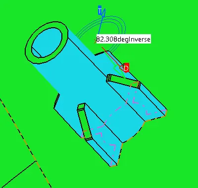 the heat stack have .5 deg inverse so the colour shold be in sky blue when check with other tooling axis it showen as green colour

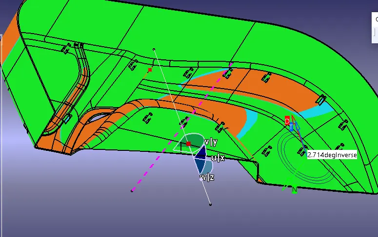
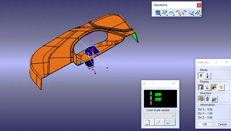
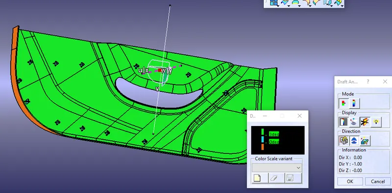
some views of part
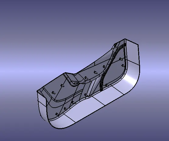
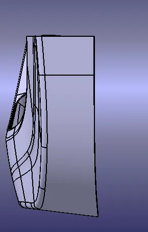
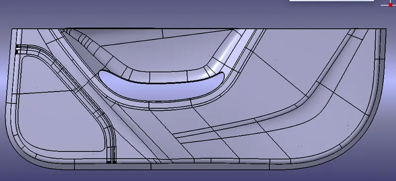
Conclusion
given class A surface to be created closed surface and locator heat stack to be created