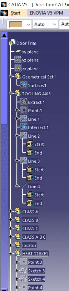
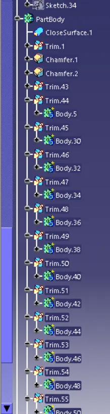
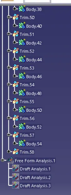
To create the Geomatry set with proper name and sub geomatry set also.
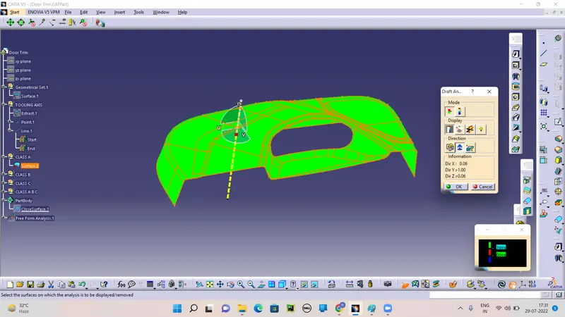
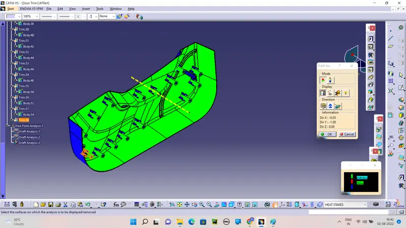
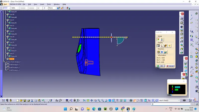
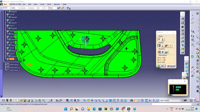
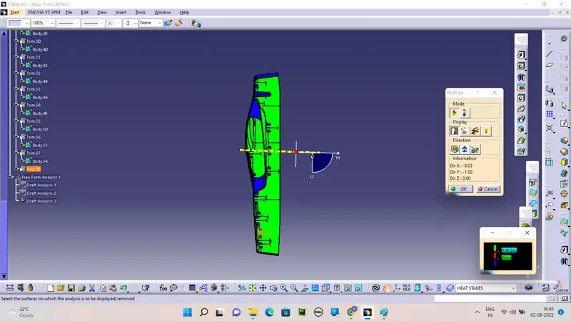
A positive draft means the angle of the face, with respect to the direction of pull, is more than the reference angle. Negative draft. Displays any faces with a negative draft, based on the reference draft angle you specified.
Ribs are a feature in plastic injection molded parts. They are thin extensions that run perpendicular from a wall or plane. They are commonly used to provide additional support and strength to a part. Thickness and location are essential to rib design.
TOOLIN AXIS:
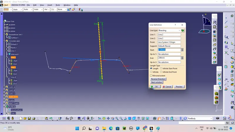
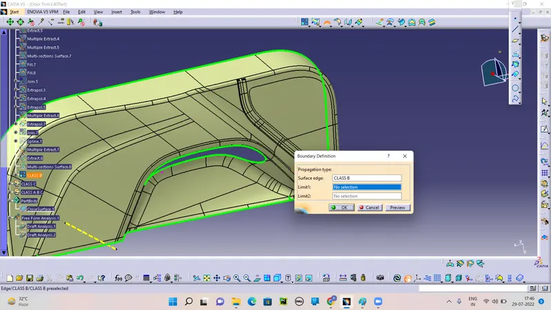
The direction in which the mold or core and cavity opens is the tooling axis. Connectivity of Class-A surface: Checking the connectivity of the surface, this can be done by creating boundaries or by simply using the join option such that any openings can be easily visualized.
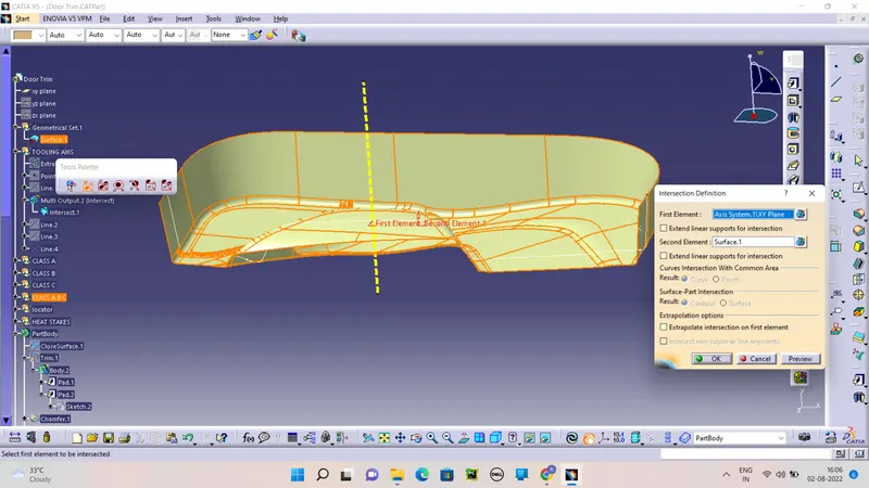
Create the Toolig Axis by the Bisection Line Command. First create the intersection of the Surface A and we get the line.
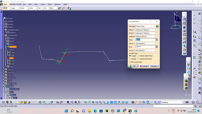
Draw the line on the Intersection curve extrant it. By the help of two line Draw the Tooling Axis.
After creating Tooling Axis Check Draft ange with Class A surface.
CREATE THE CLASS B:
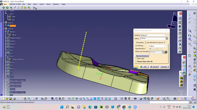
Class B is other side of the Parts. We offset the Class A to 2.5mm.
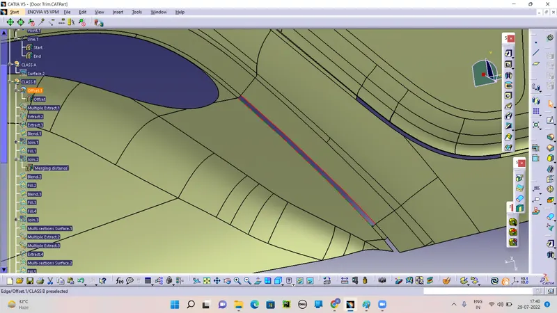
There some surface are missing while Offset of Class A.
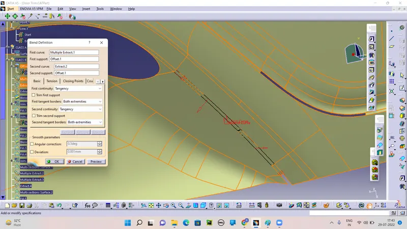
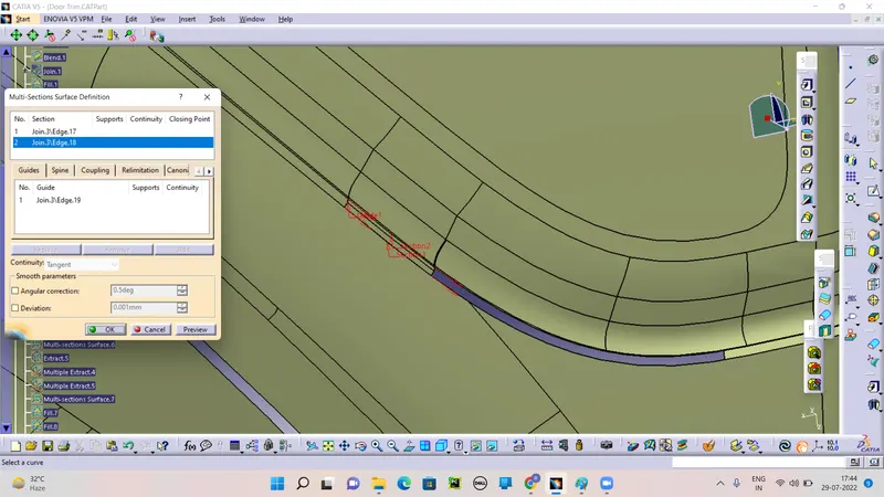
Rectify the Patch BY the Multi section surface and Sweep and Fill and Blend. (The Fill and Blend are using the Very dfficulte patch and Small area covering.)
Close all the patch and missing surface by the help of All Extrude tool.
CREARTE CLASS C:
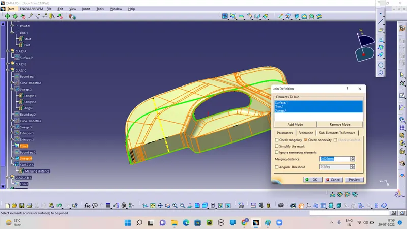
Class c is nothing but Join the Class A and Class B.
In this seen we are create the class C for Join the Class A and Class B.
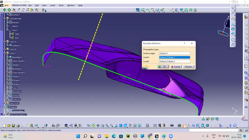
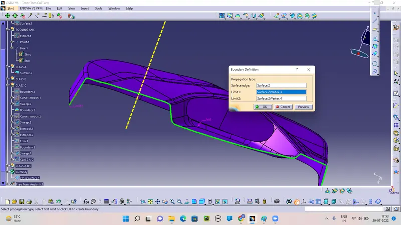
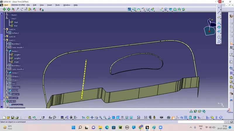
Create the boundries for the Sweep.
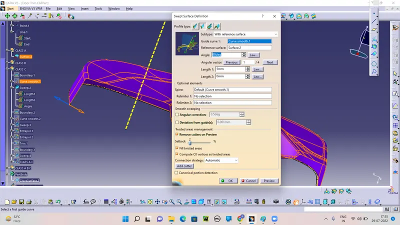
Sweep the Curve Before Make it Smooth curve.
Create all the sweep surface.
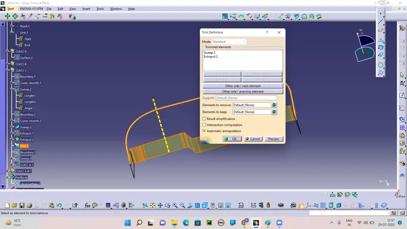
Trim the Sweep 1 and Sweep 2 to for the Proper class C.
Join all the Class C with Class A.
NOTES:
If the Self Intersection error are occurs while trim To be Extrapolate the Class B.
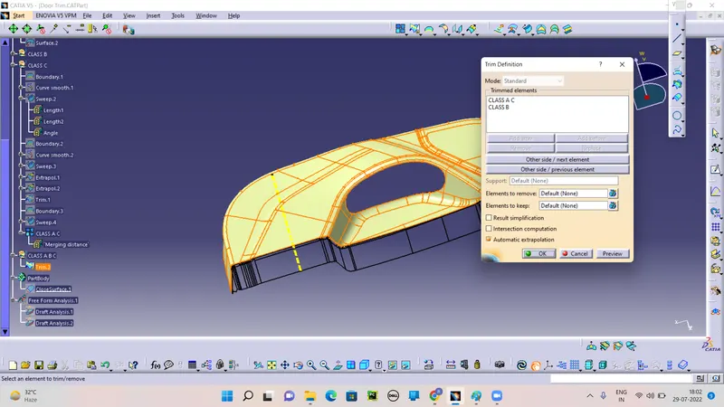
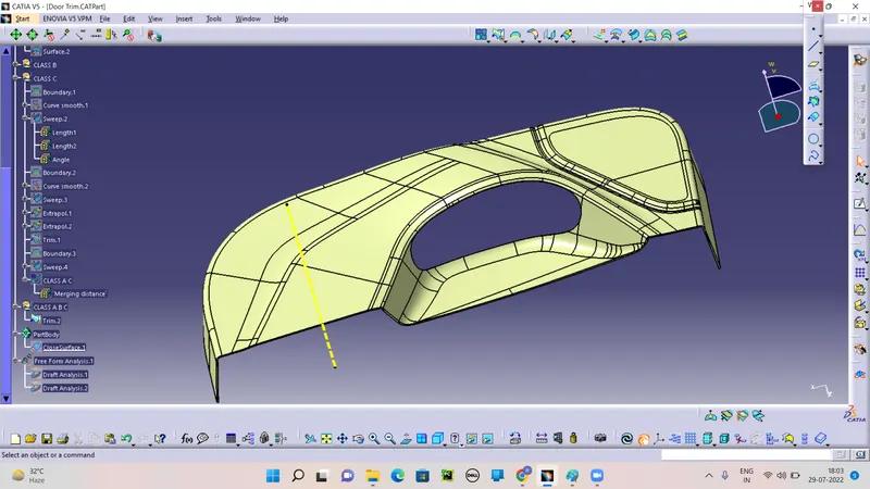
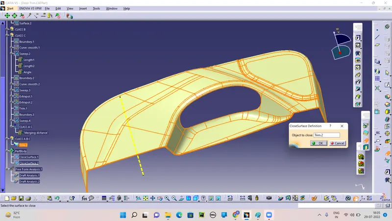
Create the Close volume surface by the Trim operation of Class AC and Class B.
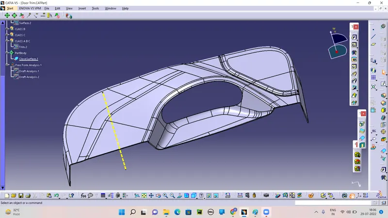
Clear Close view.
Create the Solid part in the Part workbench by the Help of Close view Tool.
Solid part.
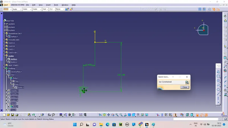
After creating the Solid part go to create the locator and heat stakes on the Plastic trim.
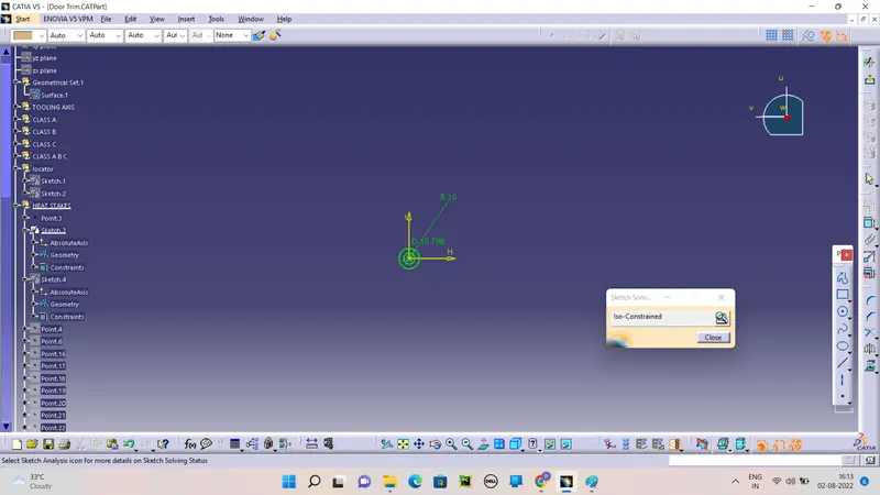
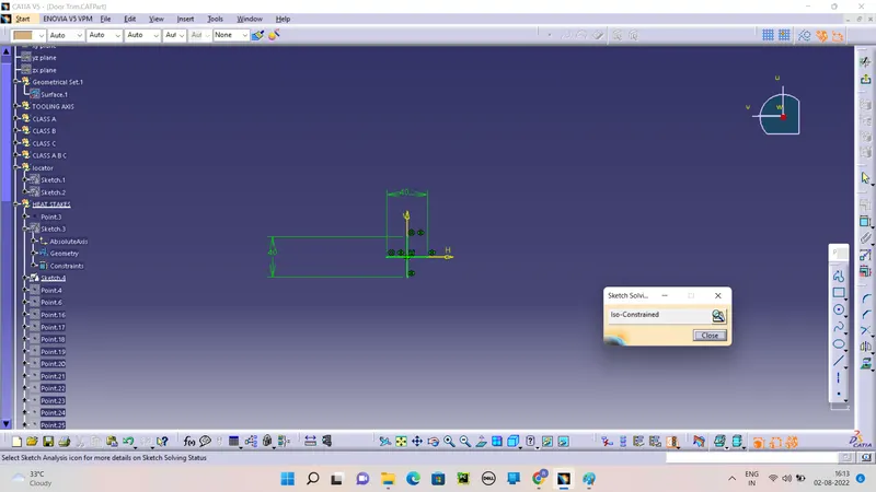
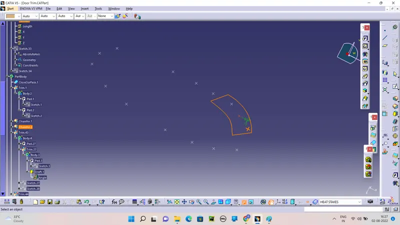
Start the sketch by the positioned sketch.
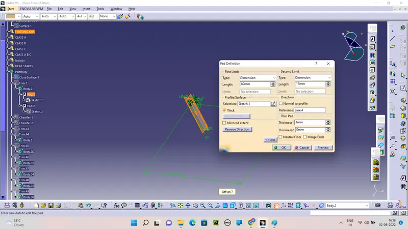
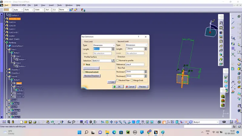
Create the new part body and Pad it with required dimension and the thick it.
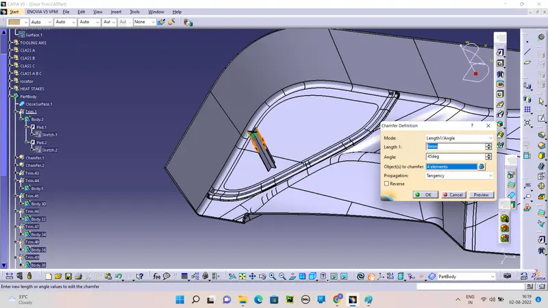
chamber it.
Like wise to another Locators.
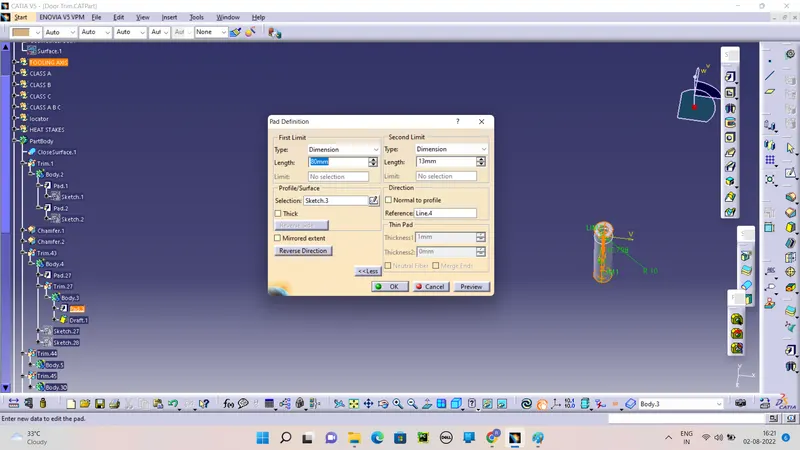
Create the Heat Stakes on part body.
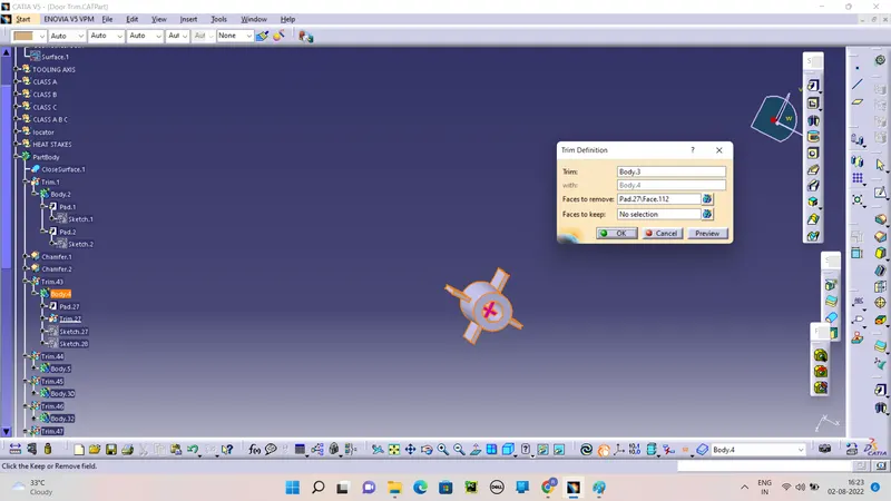
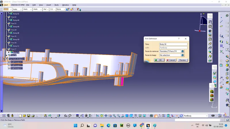
Union trim with two pads.
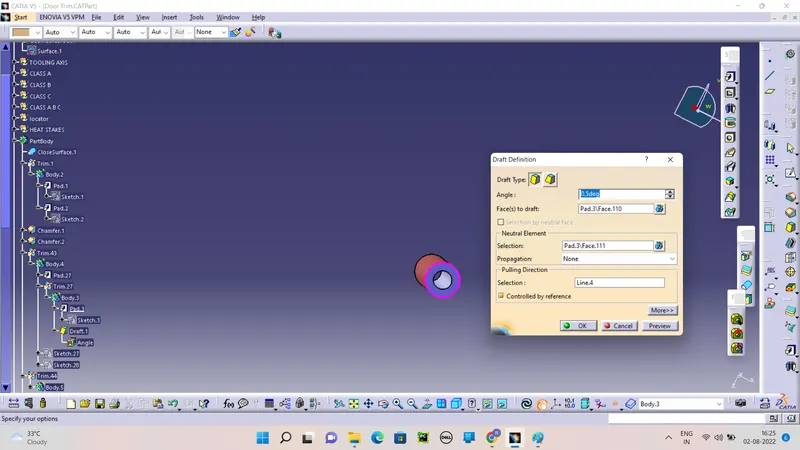
make draft angle to the Heat stakes.
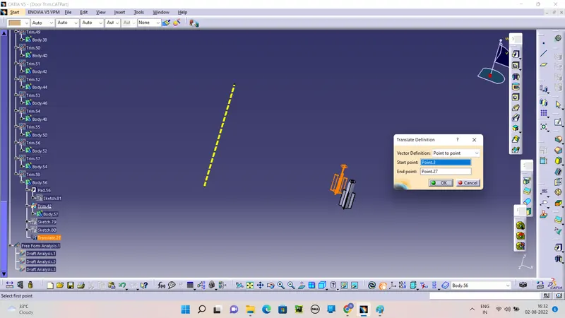
Get ready with Heat stakes Go to translet to required position by the Point to Point transalet.
First of all create the point on the surface.
After creating point copy the First done heat stakes and paste it parent and then Translate the heat stakes by the point to point option.
Like wise transelate all and union trim with base part.
NOTES:
Here we should not follow any dimension for create the heat stakes and locator.
TREE STRUCTURE:
please don't consider name's of features.
3D PART ORIENTATION WITH DRAFT ANGLE ANALYSIS:
ISOMATRIC VIEW:
FRONT VIEW:
SIDE VIEW:
TOP VIEW: