DOOR TRIM LOWER DESIGN USING CATIA v5
Door Trim Lower with Engineering Features
AIM: To Create the Door Trim Lower Plastic component through the given Class-A surface. To begin with, the tooling axis for the given Class-A Surface should be created meeting the requirements of the draft angle and at the end perform the Draft analysis on the model.
OBJECTIVE;
- To Create Tooling Axis.
- To Create Class B and Class C Surface.
- To Create Solid Body Out of Surface Modelling.
- To perform Draft Analysis to given Class A and Final Plastic component.
- Thickness of component 2.5mm.
- To create B side Engineering Features.
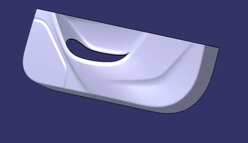
GIVEN CLASS A SURFACE:
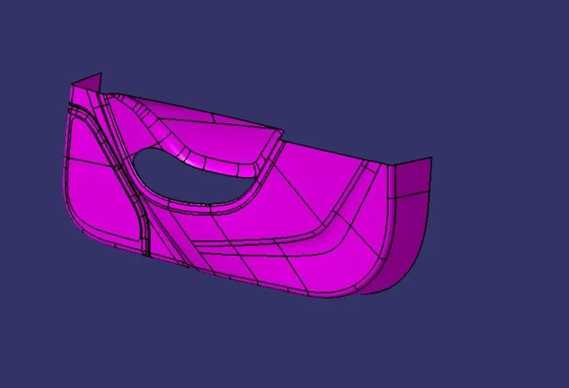
(Class-A Surface)
*To continue with the Design procedure first we have to find the Tooling axis for the surface to Check the Draft Using Draft analysis Tool.
TOOLING AXIS: The Direction in which the mold or Core and Cavity opens is Tooling axis.
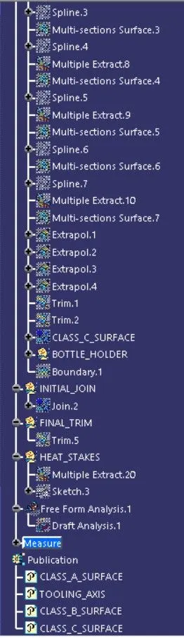
TOOLING AXIS FEATURE TREE;
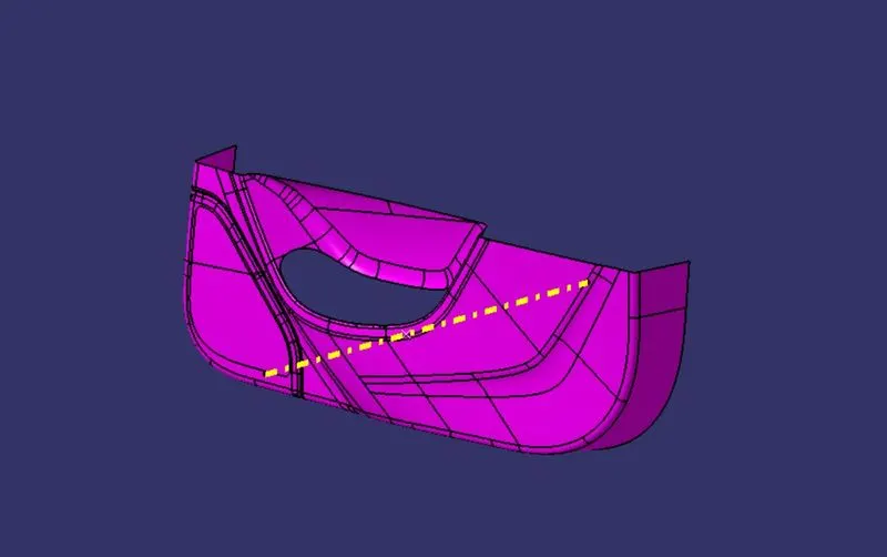
(TOOLING AXIS)
*The yellow line represnt the tooling axis
PROCDURE;
- In this above Figure we created a point on a class-A surface with the aim to move the main tooling direction.
- After creating the point in the class A surface select the line command and create a Tooling axis along Y Axis.
DRAFT ANALYSIS OF CLASS-A SURFACE :
Draft Analysis:The draft analysis technique is used to analyze whether our part model created in CAD is manufacturable based on the draft condition applied. Here the part should get easily removed from the panel dies (in case of Sheet metal part) or Mold (in case of plastic).
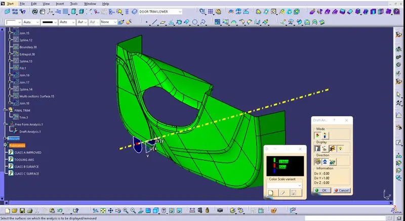
PROCEDURE;
- After creating Tooling Axis select the feature draft analysis option from the insert option,
- Select the element to analyze.
- Click on the compass to define the new current draft direction option and align it with the tooling Axis by dragging the compass to the axis.
- If the colour appears in blue, click the invert button in direction table.
CREATION OF CLASS-B SURFACE:
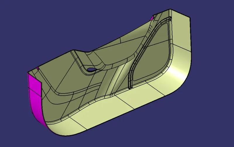
- Now for class-B creation, We have Offseted the surface from class-A surface for 2.5mm towards Class B.
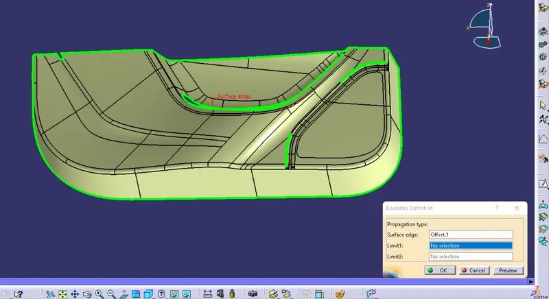
- After offsetting check for gaps or by using boundary command.
- Fill the gaps or open area using multi-section surface and surface fill command.
In this class B Surface creation we offseted the Class A surface,
Using Boundary command to check the gaps or open patches in a surface.
Patches which are formed after offseting the class A surface
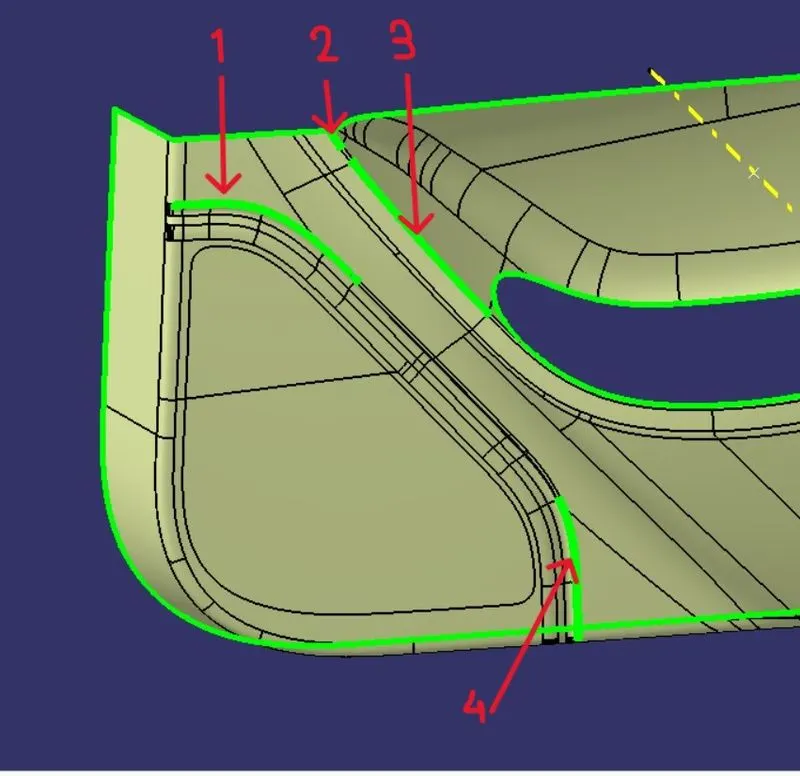
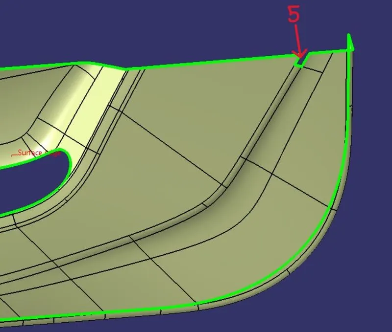
Using mutli-section surface And extract, Exptrapolation,Trim And Fillet command filled the open patches which are formed while offseting the surface.
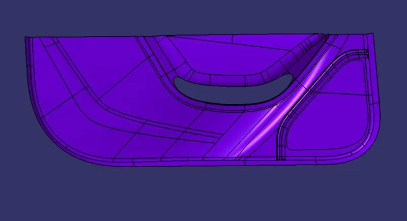
(CLASS-B SURFACE)
CREATION OF CLASS C SURFACE:
- To create the Class-C surface we have to create a boundary line by using boundary feature.
- Now the boundry line is to be swept by using sweep feature from the surface table using Line profile and with reference surface subtype with 90degree angle along the tooling axis and using With Draft Direction for 3 deg.
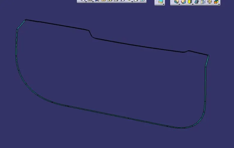
(CLASS C SURFACE)
FINAL TRIM:
In this process we are going to create a final requried closed body by Trimming the Class-A, Class-B and Class-C surface together.
TRIMMING CLASS A CLASS B AND CLASS C;
Make sure that there is are open boundry between class-A and class-C surfaces while trimming surfaces.
JOINING CLASS-A WITH CLASS-C SURFACE;
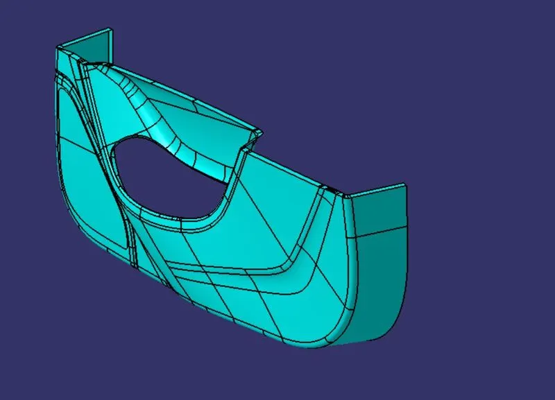
JOINING CLASS-A, C AND CLASS-B SURFACE;
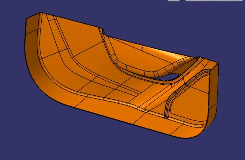
CLOSED BODY;
ENGINEERING FEATURES:
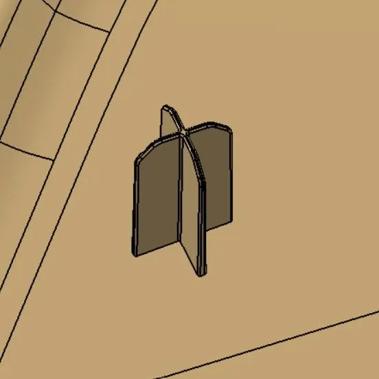
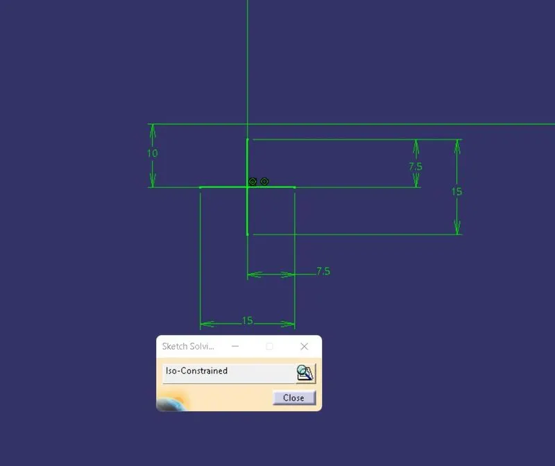
4 Way locators; 4way mean to prevent movement at 2 axes (+X, -X, +Y and -Y) on the plane. Generally, to have cylindrical pin on the fixture and circular hole at workpiece part.
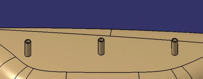
Heat Stakes; Manufacturing operations currently use many different combinations of attachment methods to keep components together. Common fasteners such as bolts, screws, and rivets can be used to form permanent attachments, but there are attachment methods that don’t require secondary hardware. One of those methods is heat staking, which doesn’t require additional fasteners.
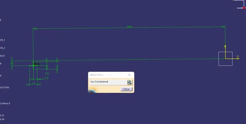
SKETCH AND DIMENSIONS;
4-ways locator:
*Using positioned sketch created the sketch
Heat Stake;
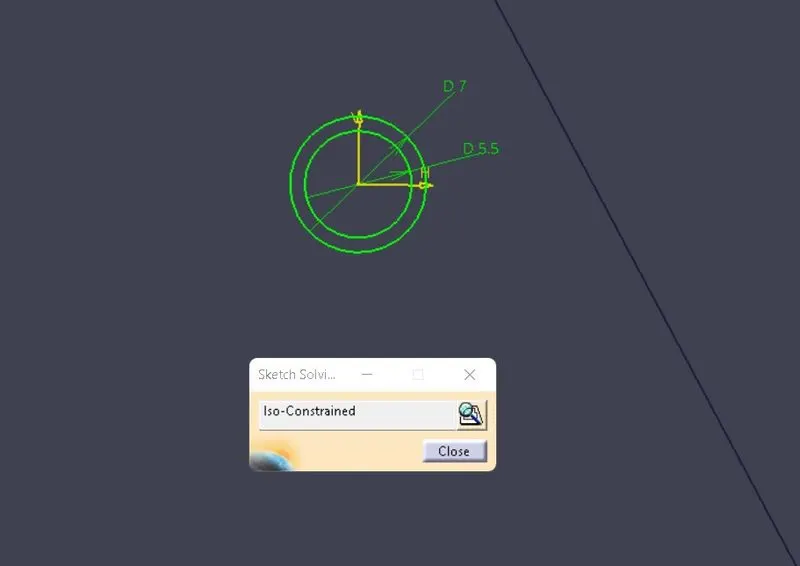
*Paded the constrained sketch then added the draft for 4-way locator.
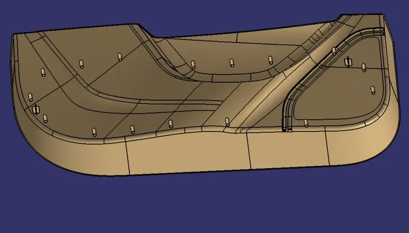
*Assembled using union trim and assemble command.
RESULT;
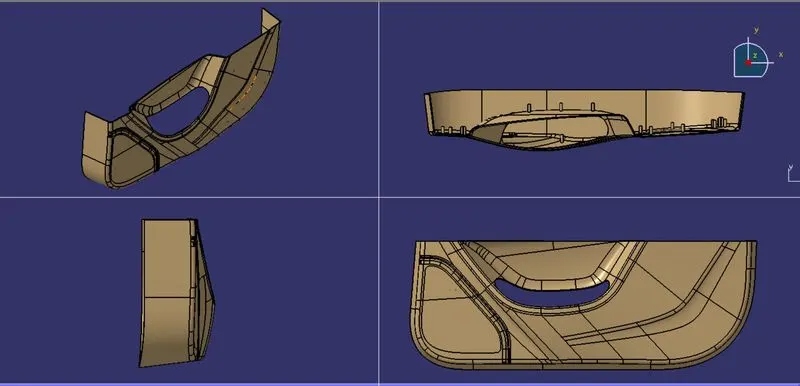
VIEWS:
DRAFT ANALYSIS FOR FINAL COMPONENT:
In this process we are going to check the draft analysis for the final closed surfaces to ensure all the surfaces are above 3 degree draft.
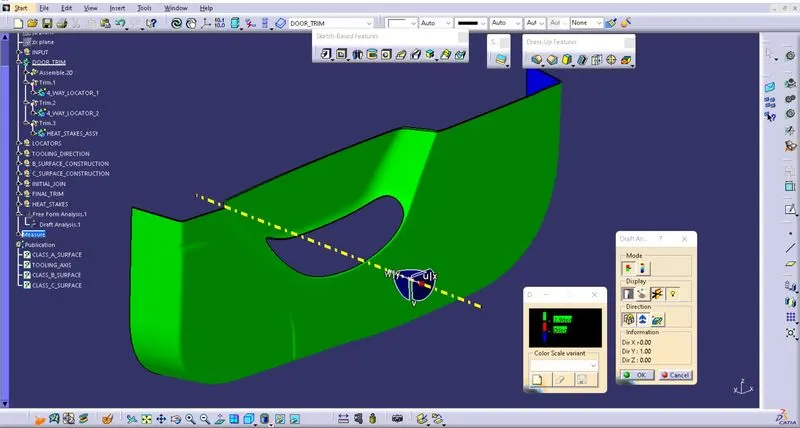
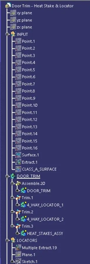
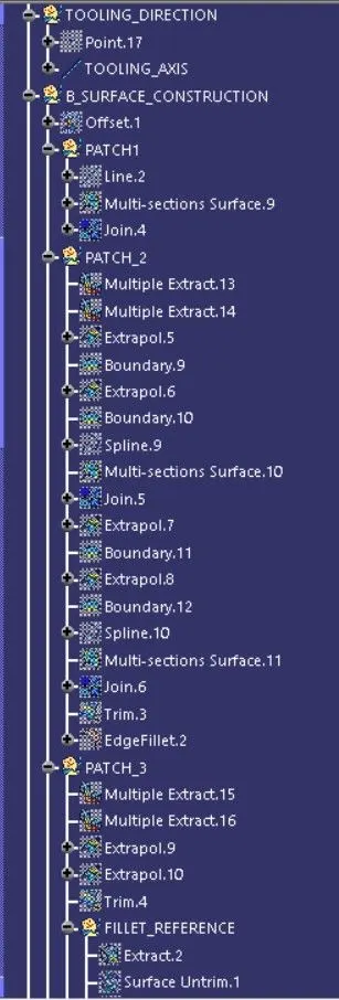
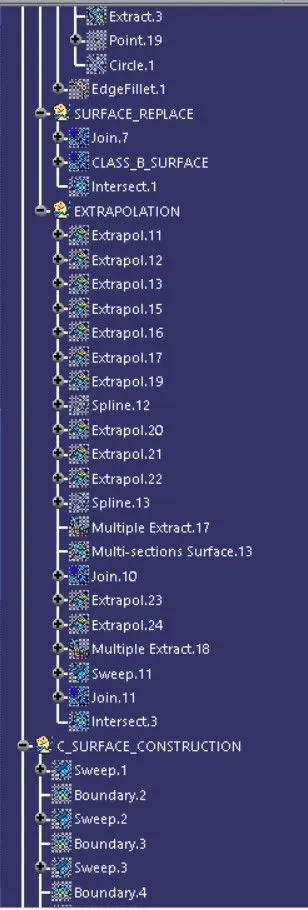
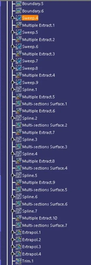
DESIGN TREE;