DESIGN OF AMERICAN CHOPPER USING SOLID WORKS
AMERICAN CHOPPER
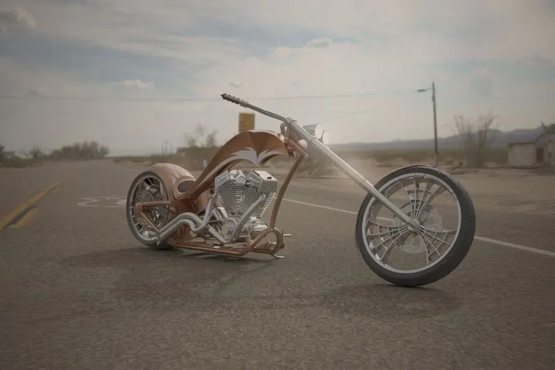
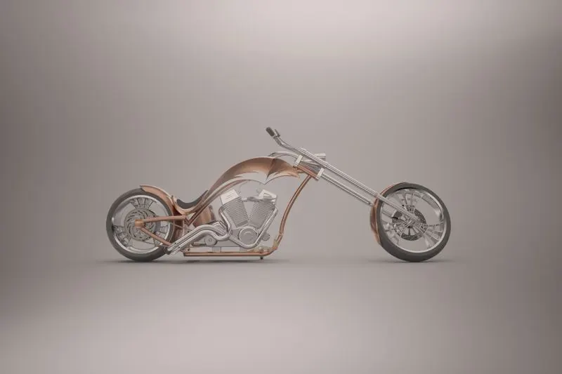
Photorealstic image of american chopper in solidworks visualize
AIM & OBJECTIVE:
*To create a model of an american chopper by modeling diffrent exterior parts Using Various sketches and feature tools in Solidworks.
*To assemble the parts of Chopper with proper tools in solidwork assembly .
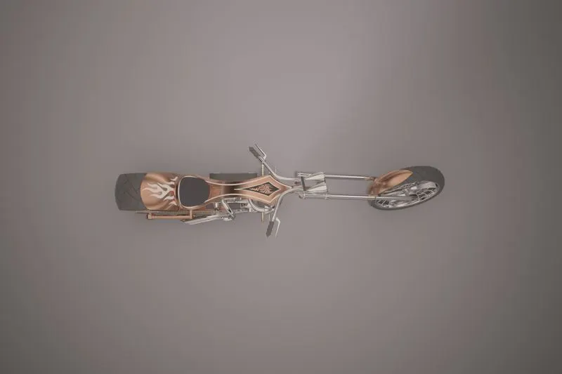
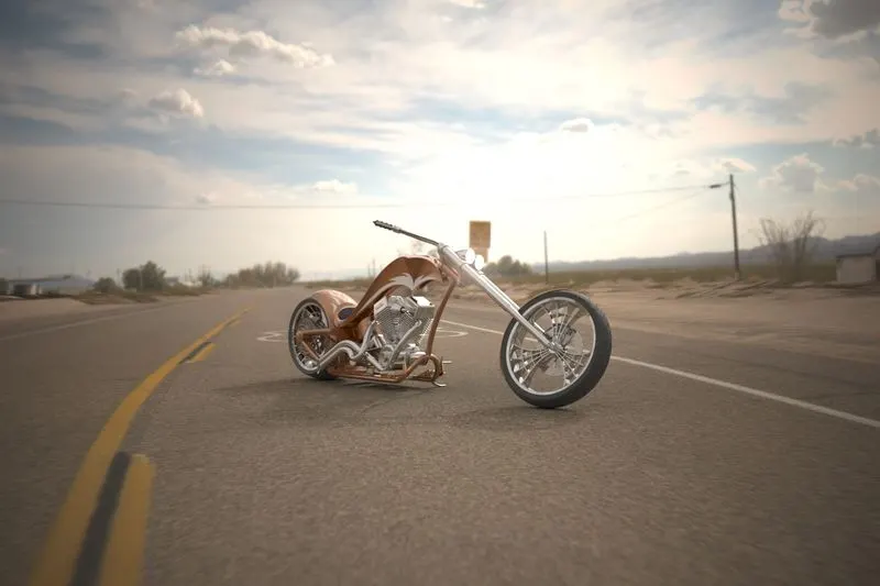
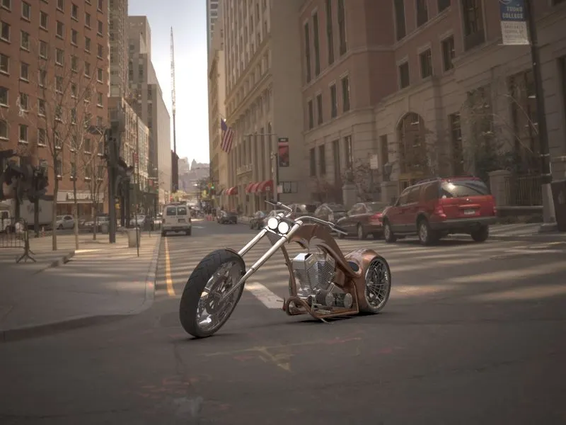
* To create a photorealistic render images of the chopper using solidworks Visualize.
INTRODUCTION:
A chopper is a custom motorcycle which emerged in california in the late 1950s. A chopper adopt radically modify steering angles and leanthered fork for a sturchured out appearance they can be built from an original motorcycle.which is modified (chopped) or built from scratch some of the characteristic features of chopper are long front ends with extended forks often coupled with am increased rake angle , hardtail frames ( frames without rear suspension),very tall "ape hanger" or very short "drag " handlebars, lengthened or stretched frames and larger than stock front wheel,the "sissy bar" a set of tubes that connect the rear fender with the frame, and whichare often extended several feet high , is a singnatues features on many choppers
PART MODELING:
Part modeling is the process of creating a virtual prototype of something by modeling each individual part separately, which can then all be assembled together.
In part modeling we can create a part from a conceptual sketch through solid feature-based modeling, as well as build and modify parts through direct and intuitive graphical manipulation.
In this project We created the following parts;
1. Transmission belt: Transmission Belts are flexible material.The main use of transmission belt is a sourse of motion to transfer power.
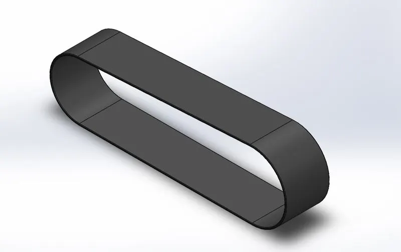
Features used to create Transmission belt;
- Sketch
- Offset
- Extrude
- Fillet
Sketch:
The sketch is a 2D representation of a particular part from different viuews such as views in solidworks software ie., Front view, Side view and Top view.
Offset:
Offset is used to create a similar sketch at required distance in required direction parallel to the sketch.
Extrude:
The extrude command is used to create a solid extrusion based on the selected sketch or contours.The extrusion made either in a positive or negative direction as required.
Fillet:
The fillet is used to creating round faces in the interior or exerior corners of the part. The fillet distributes stresses uniformly along the corners.
2. Kick stand: A kickstand is a device madeup of metal that flips down fromt the frame on a motorcycle that allows the bike to kept upright without leaning against another object
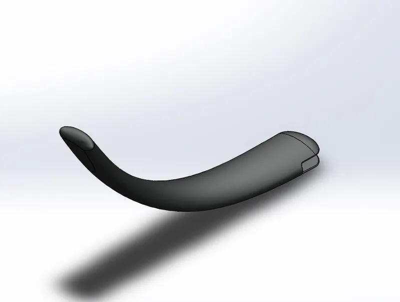
Features used to create Kick stand;
- Sketch
- Loft
- Dome
- Extrude boss
- Extrude cut
- Fillet
- spline
Loft:
The loft feature is used generate complex geometry in a single feature.It does this by interpolating surfaces between various cross-sections of a model.These cross-sections can be sketches, faces or edges. In the loft interface, these cross-sections are considered "LOFT PROFILES".
Dome:
Dome is an architecture, the hemispherical structure evolved from the arch, usually forming a ceiling or roof over the surface/face being selected.
Extrude Cut:
The extrude cut is used to remove unwanted material from solid model as per the sketch defined.Based on the sketch the material removed from the component.
Split:
The split feature is used to split a single surface into multiple surfaces based on the sketch, by using the desired sketch split surface can be performed.
3. Front Fender: Fender or mudGaurds are used to protect feet and ankles and other metal parts from spray of sand,mud when riding in the rain or even through a puddle.
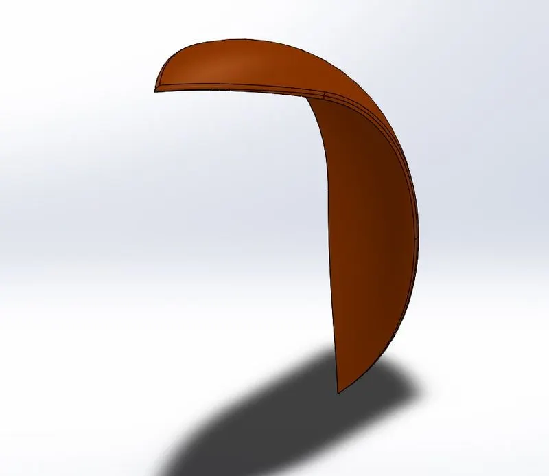
Features used to create Fender:
- Sketch
- Offset
- Trim
- Revolve
- Dynamic Mirror
- Split
Trim:
Trim is used to reomve unwanted sketch portions or entities of the sketch. It works based on some reference point edges.
Revolve:
Revolve is used to create a revovled 3D model using a sketch profile using axis of rotation. The profile created with the revolution upto 360 degree axis rotation.
4. Rear Fender: Fender or mudGaurds are used to protect feet and ankles and body of the rider and other metal parts from spray of sand,mud when riding in the rain or even through a puddle.
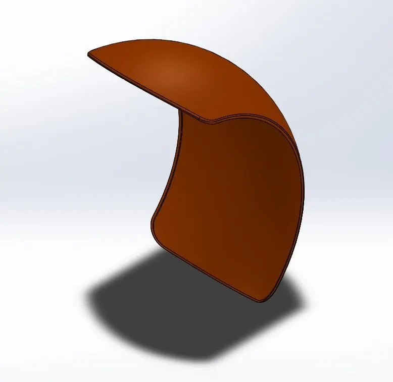
Features used to create Fender:
- Sketch
- Offset
- Trim
- Revolve
- Dynamic Mirror
- Split
Dynamic mirror:
This feature is used for creating instant symmetry within a sketch. As we create a sketch on one side of the centreline. this feature automatically create a symmetrical shape on the other side which has same relations as the sketch we're creating.
5. Oil tank: oil tank is used store lubricant of motorcycle engine.
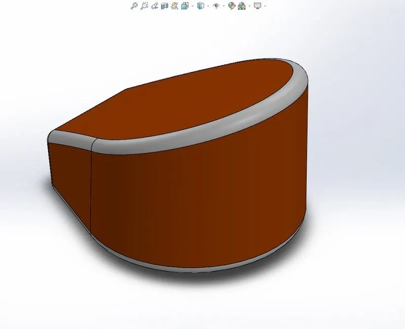
Features used to create Oil tank:
- Sketch
- Extrude boss
- combine
- fillet
- Shell
Combine:
A combine feature is used to merge multiple soild body into a sinlge solid body.
Shell:
Shell feature is used to create a thickened surface either it can be done in the interior or exterior surface. The shell tool hollows the part leaves open the faces we select and creates thin wall feature on the remaining faces.If we do select any face on the model, we can shell a solid part.
6. Chain: a motorcycle chain is a roller chain that transfers power from the engine to the drive wheel of a motorcycle.
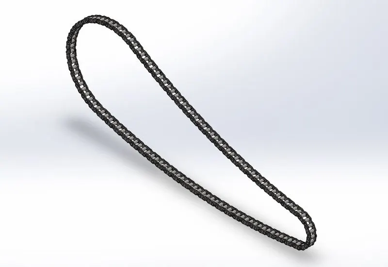
Features used to create chain:
- sketch
- fillet
- trim
- extrude boss
- patterns
Pattern:
This feature is used to create similar geometry or sketch to defined instances based on some reference, edges, vertex,etc.,
7. Pedal:Pedal or footrest is preferably for a motorcyvle provides both an upwardly angled flat surface for comfortably supporting the rider's feet.
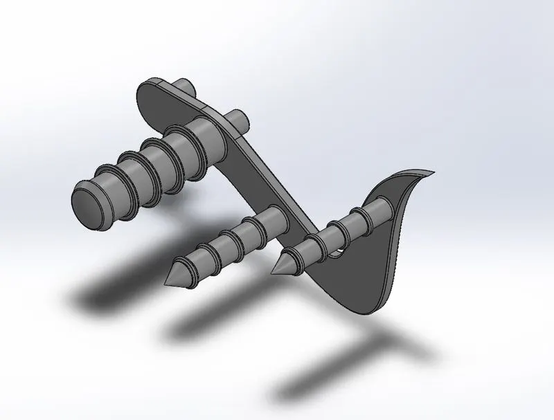
Features used to create Pedal;
- Sketch
- Extrude
- Fillet
- Linear pattern
- Dome
- Chamer
Chamfer:
The chamfer is used to create beveled features on the selected edge face and vertex according to angle or distance specified.
8. Front wheel: Wheel is a circular object that revolves on a axel and is fixed below the motorcycle.
Wheel consists of
- Rim
- Tyre
- Breake caliper
- disc
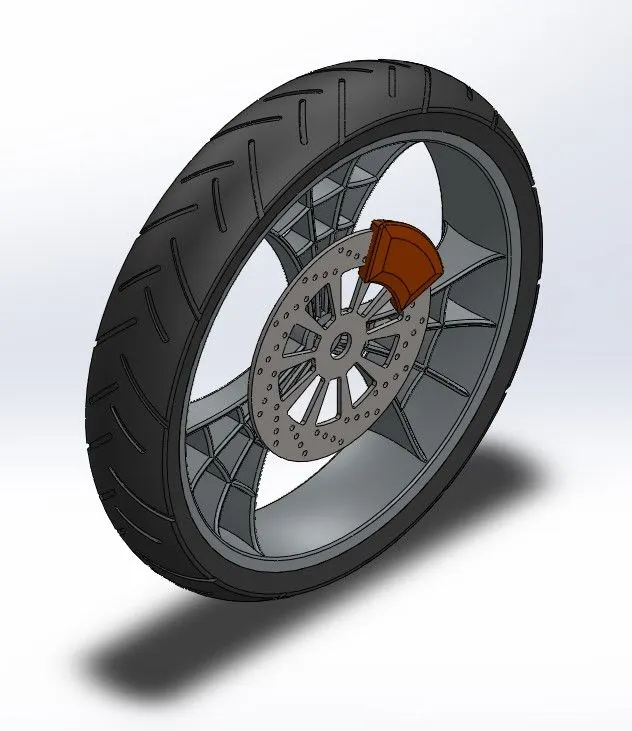
Features used to create front wheel:
- Sketch
- Revolve
- Trim
- Fillet
- Extrude boss
- Revolve cut
- Linear pattern
- Circular pattern
- Chamfer
Circular Pattern:
A circular pattern is used to create a solid feature in a circular direction eith respect to the reference axis of rotation up to user defined instances.
Revolve cut:
Revolve cut is used to remove solid geometry by revolving the sketch profile along a reference axis from the selected solid body.
9. Rear wheel: Wheel is a circular object that revolves on a axel and is fixed below the motorcycle.
Rear wheel consists of
- Rim
- Tyre
- Brake Caliper
- Disc
- Sprocket
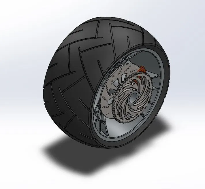
Features used to create Rear wheel:
- Sketch
- Revolve
- Trim
- Fillet
- Extrude boss
- Revolve cut
- Linear pattern
- Circular pattern
- Chamfer
10. Front fork:A motorcycle fork is the part of a motorcycle that holds the front wheel and the handle bar.
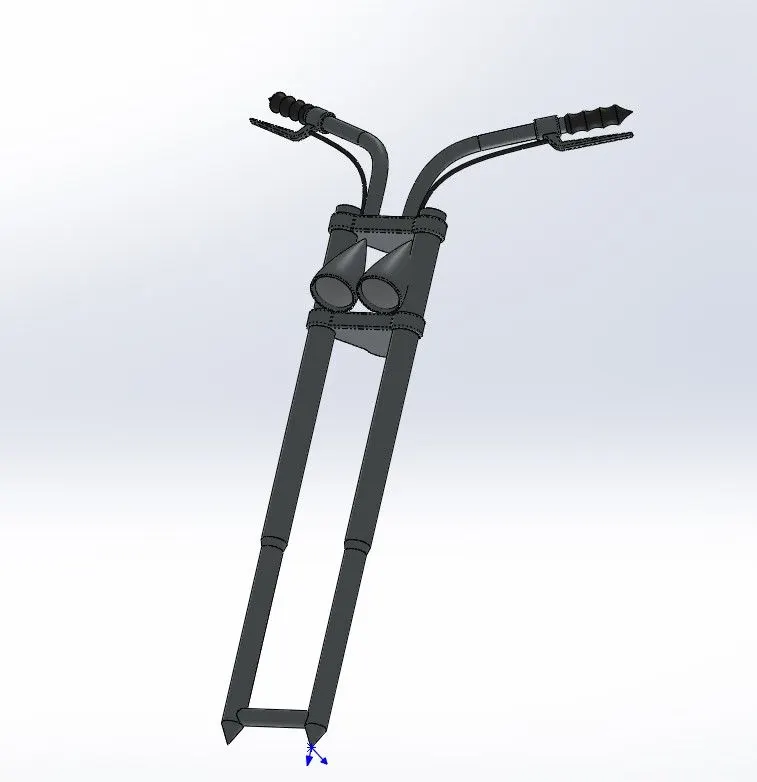
Features used to create Front fork:
- Sketch
- Extrude
- Trim
- Revolve
- Split
- Move/copy body
- Dome
- Sweep
- Reference Geometry
- Chamfer
- Fillet
Sweep:
Sweep is used to create solid by sweeping a closed or open sketch profile in one plane along the closed or open path along the same or another plane.
Reference Geometry:
Reference geometry is used to create a reference plane,axis, co-ordinate system based on one,two or three references.
11. Chassis:A chassis is the Load bearing frame work structure of an artficial object of a motorcycle, which holds every main part of a motorcycle.
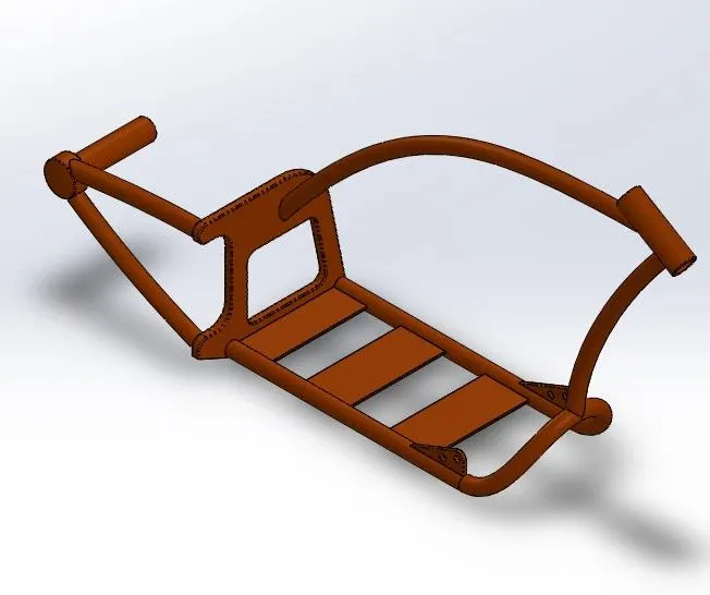
Features used to create Chassis:
- Sketch
- Offset
- Project Curve
- Trim
- Sweep
- Split
- Revolve
- Cut extrude
- Fillet
- Combine
Project curve:
The project curve is used to create a 3D curve it is created by using the reference of two 2D curves in two different planes.
12. Engine:A machine which moving parts that converts power into motion.
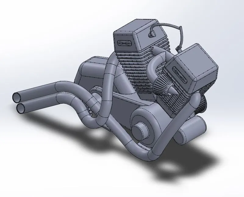
Features used to create Engine:
- Sketch
- Convert entities
- Trim
- Revolve
- Extrude boss
- Cut Extrude
- Offset
- Dome
- Project curve
- Composite curve
- Sweep
- Mirror
- Circular Pattern
- Fillet
- Split
Composite Curve:
The composite curve is used to create a combination of two composite curve in the same plane.
13. Gas tank: gas tank is a container which stores fuel of motorcycle.
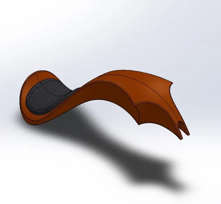
Features used to create Gas tank:
- Sketch
- Extrude boss
- Trim
- Surface sweep
- Loft Surface
- Curve-split line
- Knit Surface
- Sweep cut
- Shell
- Fillet
Sweep Surface:
This feature is used to create surface features by sweeping an open or closed sketch profile along an open or closed path.
Loft Surface:
It is used to create a surface between two or more profiles using one guide profile.
Sweep Cut:
It is used to cut a solid geometry by sweeping a closed profile along a closed or open path.
ASSEMBLY
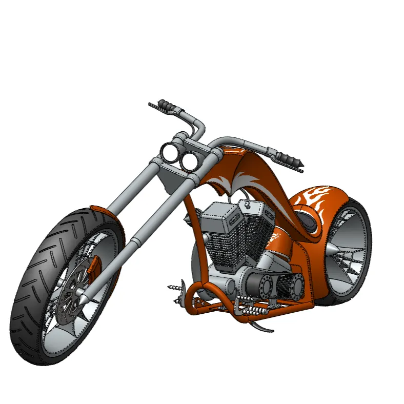
Image of the American chopper in assembly
Assembly modeling is a combination of two or more components using parametric relationships.Typically a designer would start with a base part, add other components to the base part usig merge commands.
Assembly modeling is a tool that allows and faciliates the collabration among designers, analysis people, manufacturing people, and others, to insure their assembly works together.
In assembly part we can add decals and change the appearence the model.
RENDERING
Rendering is the process of creating a raster image based on the 3D objects in a scene. A render is used to calculate the appearence of the materials attached to the objects in a scene, and how lighting and shadows are calculated based on the lights placed in a scene.
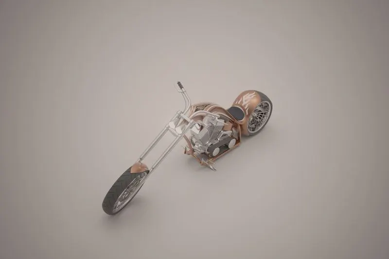
PHOTOREALISTIC RENDERED IMAGES OF AMERICAN CHOPPER
STUDIO COMPOSITION:
FRONT VIEW: LEFT SIDE VIEW:
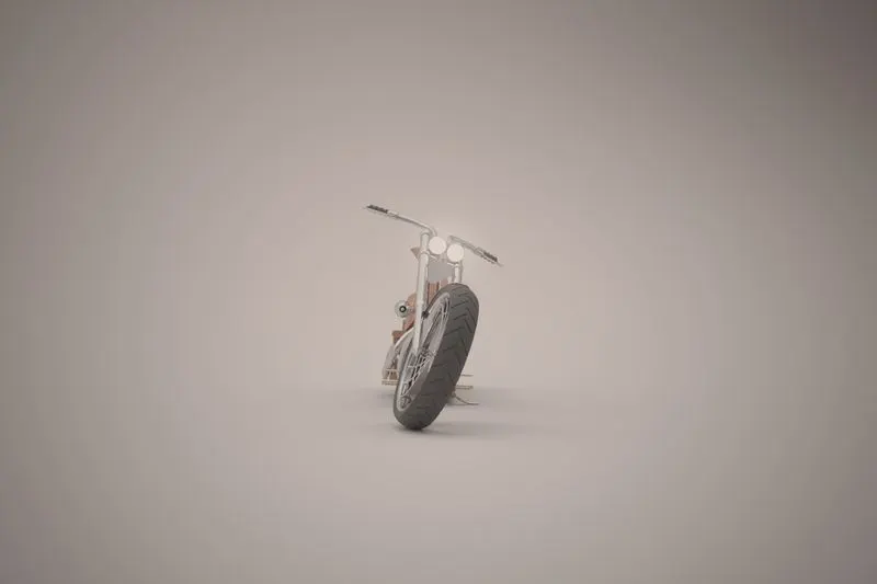
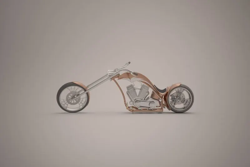
RIGHT SIDE VIEW: REAR VIEW:
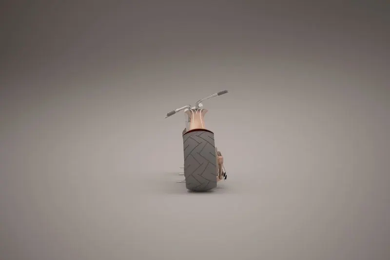
ISOMETRIC VIEW: TOP VIEW:
SCENE COMPOSITION:
Route 66:
Downtown:
CONCLUSION
All the parts of the American chopper were modelled and assembled using solidworks and created an Photorealistic renders of of the chopper by using Solidworks Visualize.