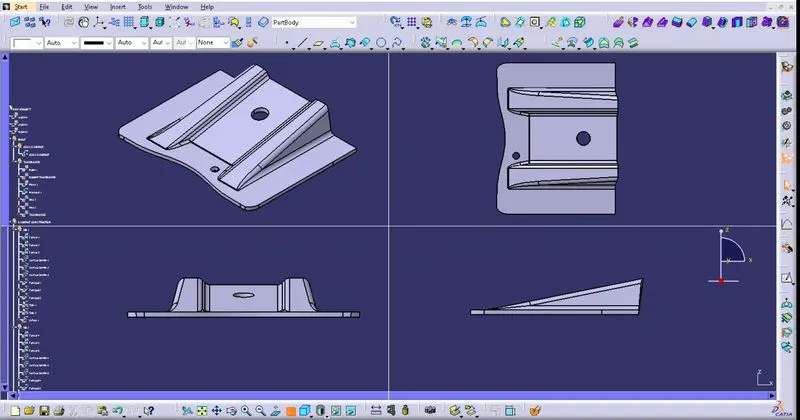
DESIGN OF BASE BRACKET USING CATIA v5
DESIGN OF BASE BRACKET
AIM: To Create the Base Bracket Plastic component through the given Class-A surface. To begin with, the tooling axis for the given Class-A Surface should be created meeting the requirements of the draft angle and at the end perform the Draft analysis on the model.
OBJECTIVES:
- To Create Tooling Axis.
- To Create Class B and Class C Surface.
- To Create Solid Body Out of Surface Modelling.
- To perform Draft Analysis to given Class A and Final Plastic component.
GIVEN CLASS A SURFACE:
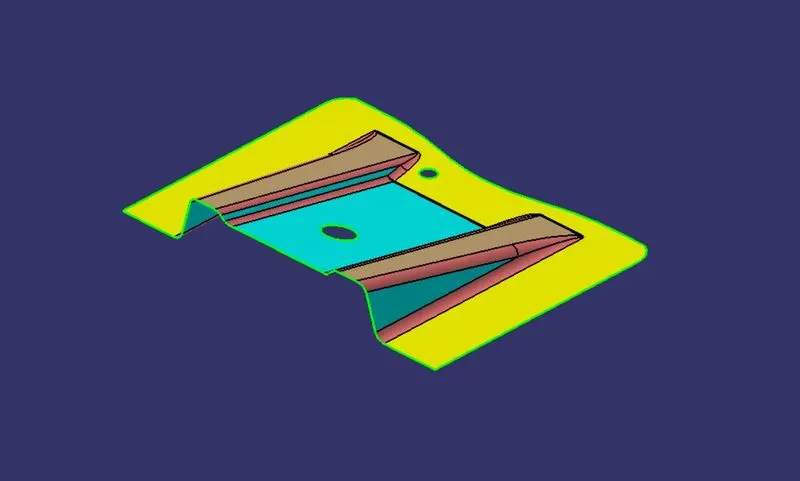
To continue with the Design procedure first we have to find the Tooling axis for the surface to Check the Draft Using Draft analysis Tool.
TOOLING AXIS: The Direction in which the mold or Core and Cavity opens is Tooling axis.
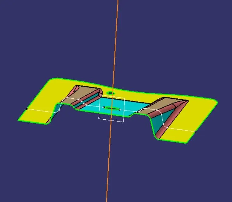
* The orange verticle line represent our tooling axis
PROCDURE;
- In this above Figure we created a point on a class-A surface with the aim to move the main tooling direction.
- Created a new palne along YZ plane with the point support to create intersection line for given Class-a surface.
- After creating the intersecting lines select the line command and create two bisecting line as shown in below image to create a tooling axis line.
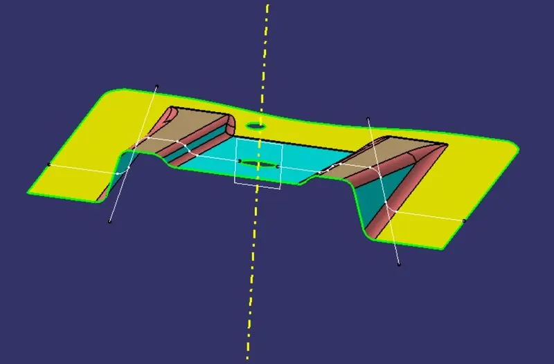
* The dotted yellow line represent tooling axis.
DRAFT ANALYSIS OF CLASS-A SURFACE;
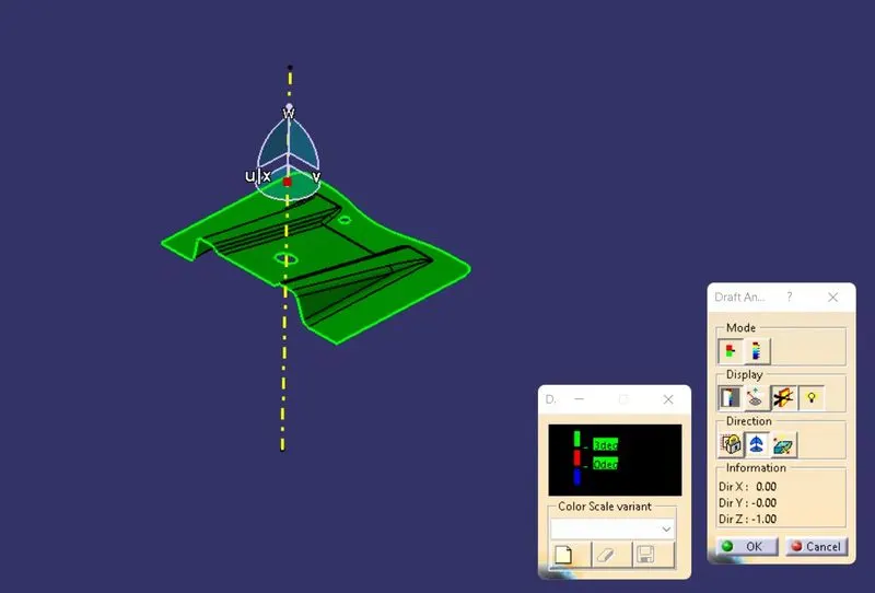
The analysis is done for 3degree draft as shown in below image,
PROCEDURE;
- After creating Tooling Axis select the feature draft analysis option from the insert option,
- Select the element to analyze.
- Click on the compass to define the new current draft direction option and align it with the tooling Axis by dragging the compass to the axis.
- If the colour appears in blue, click the invert button in direction table.
CREATION OF CLASS-B SURFACE:
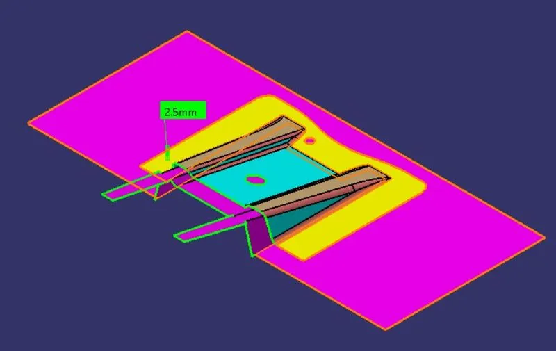
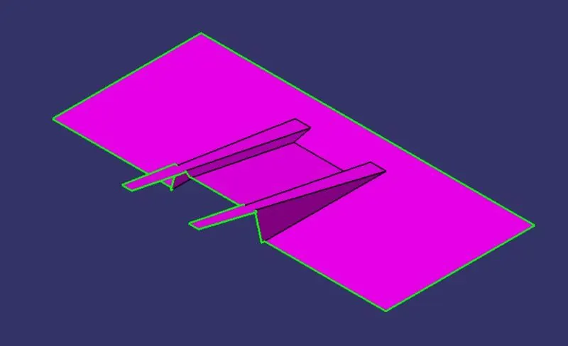
- Now for class-B creation, We have to extract the surface from class-A surface part by part.
- These extracted surface should be untrimmed and extrapolated.
- Trim the extrapolated surface as recommended and offseted the surface to 2.5mm
- Required Fillets are given to the surface.
CREATION OF CLASS C SURFACE:
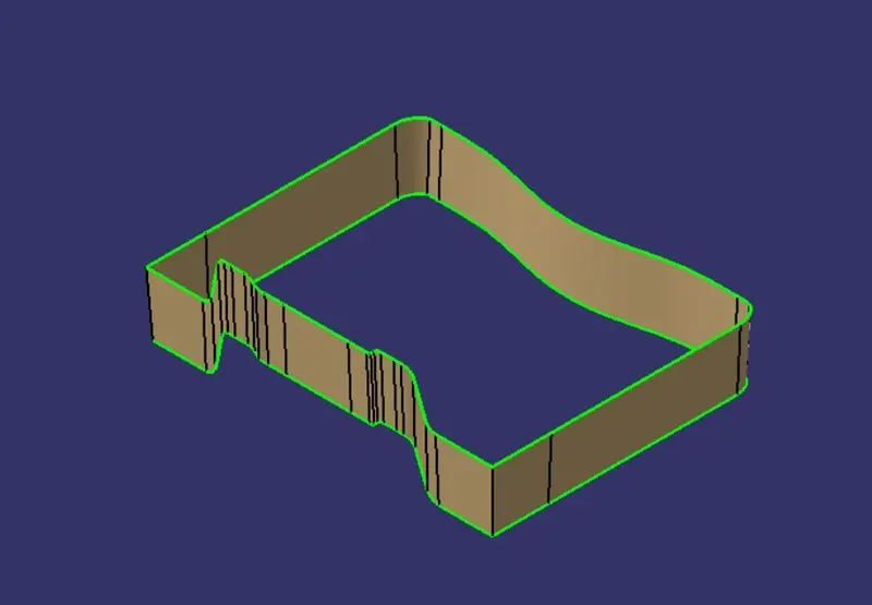
- To create the Class-C surface we have to create a boundry line by using boundry feature.
- Now the boundry line is to be swept by using sweep feature from the surface table using Line profile and with draft direction subtype with 3 degree angle along the tooling axis.
FINAL TRIM:
In this process we are going to create a final requried closed body by Trimming the Class-A, Class-B and Class-C surface together.
TRIMMING CLASS A CLASS B AND CLASS C;
Make sure that there is are open boundry between class-A and class-C surfaces while trimming surfaces.
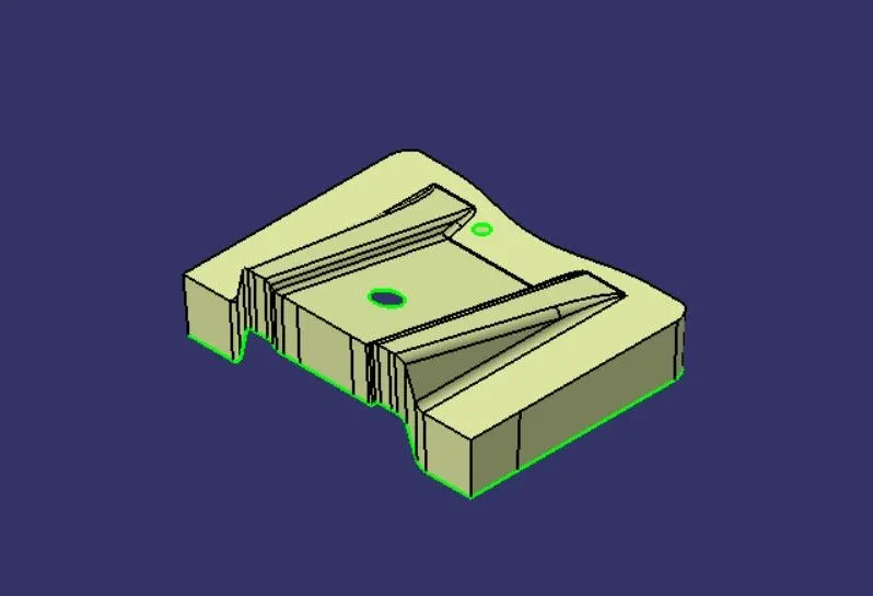
JOINING CLASS A AND CLASS B;
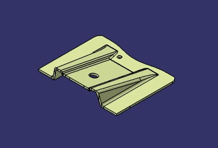
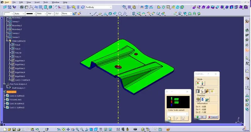
DRAFT ANALYSIS FOR FINAL COMPONENT:
In this process we are going to check the draft analysis for the final closed surfaces to ensure all the surfaces are above 3 degree draft.
CLOSED BODY:
In this process we are Creating a closed body in part workbench to create a final output component.
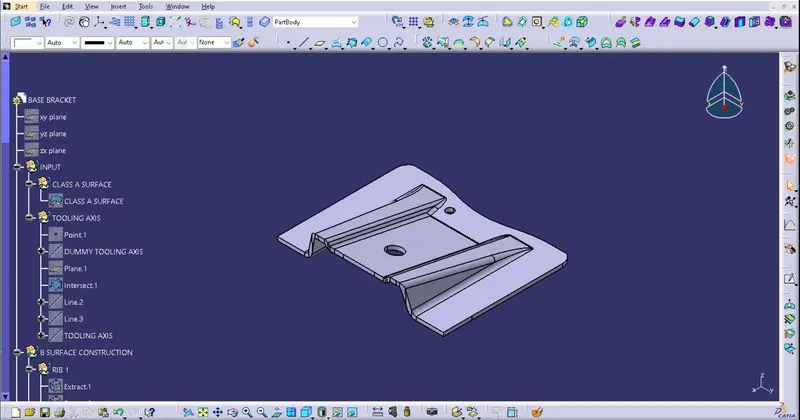
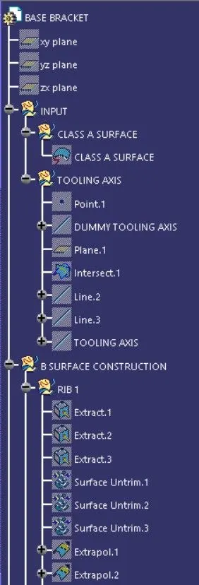
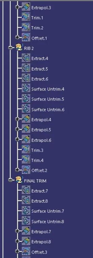
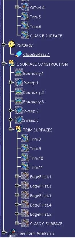
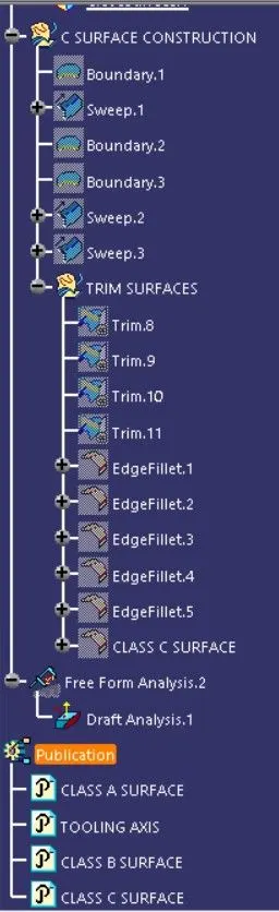
DESIGN TREE:
RESULT: