SEAWAYACHT (YACHT DESIGN) USING SOLIDWORKS
YACHT ASSEMBLY AND RENDERING
Design, Assembly and Photorealistic rendering of an Yacht
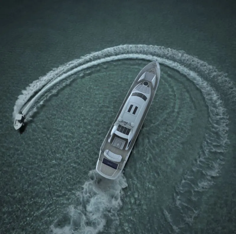
Photorealistic rendered image of an Yacht in Solidworks Visualize
AIM & OBJECTIVE:
* To setup the blueprint of the Yacht to model the parts.
* To create a model of an Yacht by modeling diffrent exterior parts Using Various sketches and feature tools in Solidworks.
* To assemble the parts of Yacht with proper tools in solidwork assembly.
* To create photorealistic render images of the Yacht using solidworks Visualize.
INTRODUCTION:
A yacht is a sail or powered vessel used for pleasure,crusing and racing. there is no standard defination, so the term applies to such vessels that have a cabin with amenities that accomodate overnight use.
Design of yacht involves creating individual parts and assembling them with respect to their proper constrains and mates.
PART MODELING :
Part modeling is the process of creating a virtual prototype of something by modeling each individual part separately, which can then all be assembled together.
In part modeling we can create a part from a conceptual sketch through solid feature-based modeling, as well as build and modify parts through direct and intuitive graphical manipulation.
In this project We create the following parts;
- Propeller
- Radar
- Hull
- Garage door
- Front seat
- Middle seat
- Rear seat
- Super structure
- Radar mast
TOOLS USED;
CREATING 2D SKETCH: A 2D sketch is the base to create a 3D model. It is usually created on the X-Axis and Y-Axis. this includes lines, circles, rectangles,Splines,etc.
TRIM: The trim tool is used to remove or erase the unwanted or extra edges of intesecting lines of 2D sketch.
OFFSET: Adding sketch entities by offseting faces,curves or sketch entities to specified distance.
BOSS EXTRUDE: The extrude command is used to create a solid extrusion based on the selected sketch or contours.The extrusion made either in a positive or negative direction as required.
CUT EXTRUDE: The extrude cut is used to remove unwanted material from solid model as per the sketch defined.Based on the sketch the material removed from the component.
REVOLVED CUT: Revolve cut is used to remove solid geometry by revolving the sketch profile along a reference axis from the selected solid body.
REVOLVED EXTRUDE: Revolve is used to create a revovled 3D model using a sketch profile using axis of rotation. The profile created with the revolution upto 360 degree axis rotation.
SWEPT BOSS: Sweep is used to create solid by sweeping a closed or open sketch profile in one plane along the closed or open path along the same or another plane.
LOFT:The loft feature is used generate complex geometry in a single feature.It does this by interpolating surfaces between various cross-sections of a model.These cross-sections can be sketches, faces or edges. In the loft interface, these cross-sections are considered "LOFT PROFILES".
DOME: Dome is an architecture, the hemispherical structure evolved from the arch, usually forming a ceiling or roof over the surface/face being selected.
COMBINE: A combine feature is used to merge multiple soild body into a sinlge solid body.
FILLET: The fillet is used to creating round faces in the interior or exerior corners of the part. The fillet distributes stresses uniformly along the corners.
CHAMFER: The chamfer command is used to connect two adjacent faces using an inclined line.
SURFACE EXTRUDE: Using this feature, we can extrude the boundary edges of a face of a solid body or edges of a surface body in a customized direction. A planar surface body is used to extrude its boundary edges.
RULED SURFACE: This feature inserts a ruled surface from the selected edges.
EXTEND SURFACE :Extends the edge, multiple edges or the face on a surface, based on end conditions and extension type.
SURFACE FILL: Constucts a surface patch whitin a boundary defined by existing model edges, sketches or curves.
BOUNDARY SURFACE: Creates a boundary surface betwwen two or more profiles.
LOFTED SURFACE: It is used to create a surface between two or more profiles using one guide profile.
SURFACE KNIT:Combines two or more ajacent, non- intersecting surface together.
SHELL: Shell feature is used to create a thickened surface either it can be done in the interior or exterior surface. The shell tool hollows the part leaves open the faces we select and creates thin wall feature on the remaining faces.If we do select any face on the model, we can shell a solid part.
MIRROR: This allows to mirror features,face and bodies along a face or a palne.
SPLIT LINE: Projects a sketch to curved or planar faces, creating multiple separate faces.
LINEAR PATTERN: This feature is used to create similar geometry or sketch to defined instances based on some reference, edges, vertex,etc.,
CIRCULAR PATTERN: This features is used patterns features,faces and bodies around an axis.
PROJECTED CURVE: The project curve is used to create a 3D curve it is created by using the reference of two 2D curves in two different planes.
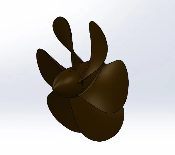
1. PROPELLER:
A propeller is a type of a fan which converts rotational motion in thrust to transmit power. A pressure difference is generated between the airfoil shaped blade from forward and rear surfaces and the pressure difference accelerates a fluid. Most marine propellers are screw propellers with helical blades revovling around an approximately horizontal axis of propeller shaft.
Tools used to model The Propeller;
- Sketch
- Revolve
- Loft
- Cut extrude
- Circular pattern
- Fillet
2. RADAR:
Radar is Device which is used to detect other nearby ships land barriers to provide bearings and distances for the prevention of collisions and navigation at the sea. They are electronic navigation instruments that uses a rotating antenna to sweep a narrow beam of microwaves around the water surface and around the ship to the horizon
Tools used to model the Radar;
- Boss Extrude
- Cut Extrude
- Sketch Pattern
- Split Line
- Mirror
- Fillet
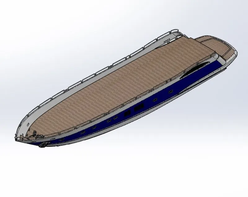
3. HULL:
A hull is the watertight body of a ship or boat. The hull may open at the top and it may be fully or partially covered with a deck.the design of hull involved preparation of outer shell is drafted with the required curves intially and are extruded and lofted to obtain the required surface.
Tools used to model the Hull;
- Sketch
- Projected Curve
- Surface Loft
- Surface trim
- Surface Extrude
- Surface Knit
- Surface Fill
- Shell
- Cut Extrude
- Fillet
- Chamfer
- Sweep
- Boss Extrude
- Revolve
- Dome
- Helix/Spiral
- Linear Pattern
- Add/Delete Face
- Thin Cut Extrude
- Split
- Split Line
- Offset Surface
- Mirror
4. GARAGE DOOR:
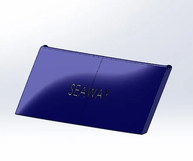
Garage door is the part that is extracted from the hull structure rear part using split entities option and been saved using different file.
Tools used to model the Garage Door;
- Cut Extrude
- Shell
- Mirror
- Fillet
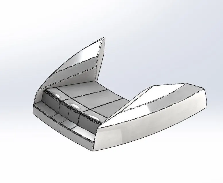
5. FRONT SEAT:
It is palced in front of the superstructure on the hull for resting and sitting.
Tools used to model the Front Seat;
- Surface Sweep
- Surface Extrude
- Surface Fill
- Surface Trim
- Surface Loft
- Surface Knit
- Revolve
- Cut Extrude
- Cut thin Extrude
- Chamfer
- Fillet
- Mirror
- Dome
6. MIDDLE SEAT:
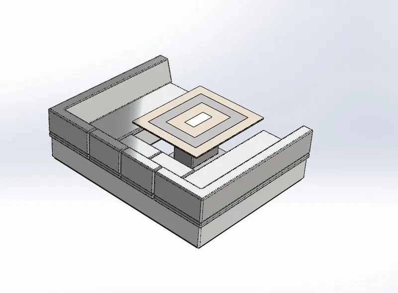
Middle seat is placed in the shaded area closely behind the superstructure backdoor.This was designed after importing the desk suface of the hull interface surface.
Tools used to model the Middle Seat;
- Boss Extrude
- Mirror
- Cut Extrude
- Chamfer
- Fillet
7. REAR SEAT:
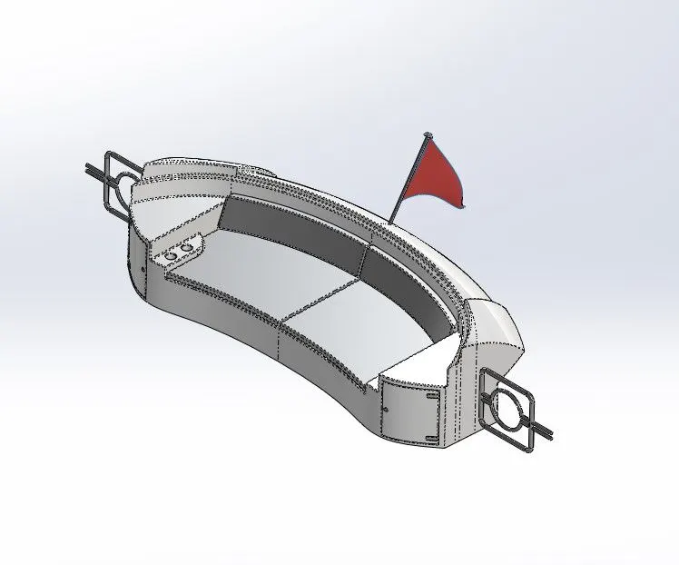
It is used for the purpose of rest at back side of the yacht , it is placed behind the middle seat on hull.
Tools used to model the Rear Seat;
- Surface Sweep
- Surface Offset
- Surface Trim
- Ruled Surface
- Surface Knit
- Surface Extend
- Surface Extrude
- Surface Loft
- Boss Extrude
- Cut Extrude
- Chamfer
- Boss Sweep
- Mirror
- Revolve
- Fillet
8. SUPERSTRUCTURE:
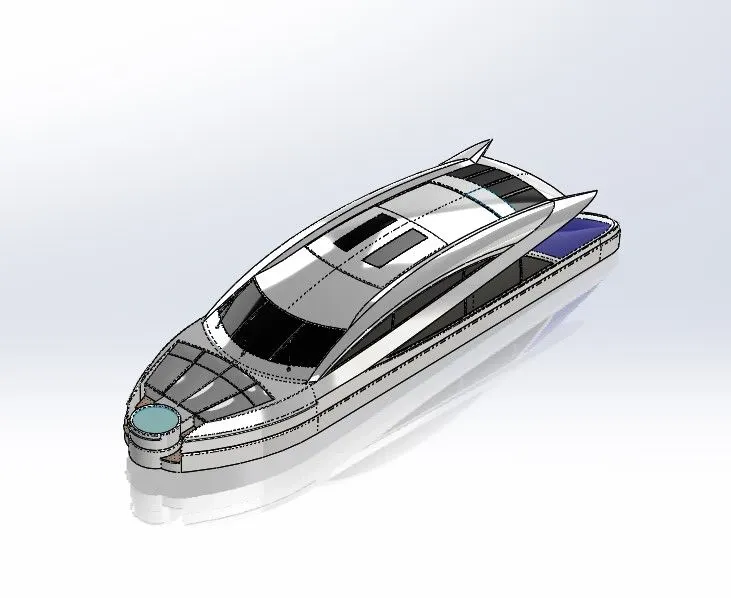
A superstructure is an upward extension of an hull, the superstructure is for control the yacht.It usually serves the purpose of structures intended use.
Tools used to model the superstructure;
- Surface Sweep
- Surface Knit
- Project Curve
- Surface Loft
- Surface Fill
- Surface Extrude
- Surface Trim
- Ruled Surface
- Surface Extend
- Fillet
- Cut Extrude
- Face Delete
- Boss Extrude
- Surface Offset
- Thickness
- Dome
- Boss Sweep
- Extrude Thin
- Split Line
- Mirror
- Chamfer
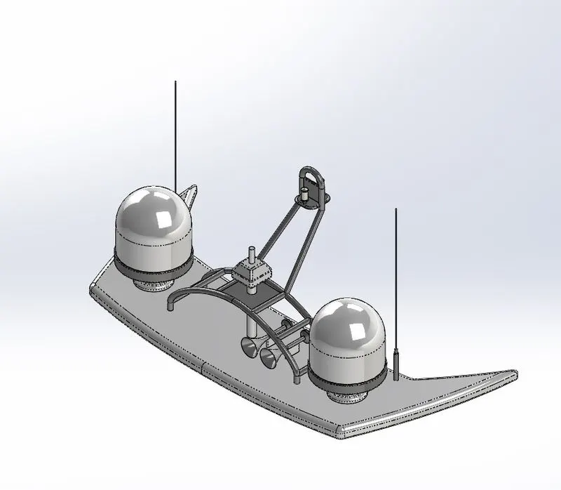
9. RADAR MAST:
Radar mast is device where the radar is fixed to control the positon and direction of radar. It is also processes the signals which are sent and received. it is modelled based on the deck surface imported from the superstructure.
Tools used to model the Radar mast;
- Boss Extrude
- Revolve
- Fillet
- Boss Sweep
- Mirror
- Project Curve
- Chamfer
- Mirror
ASSEMBLY:
Assembly modeling is a combination of two or more components using parametric relationships.Typically a designer would start with a base part, add other components to the base part usig merge commands.
Assembly modeling is a tool that allows and faciliates the collabration among designers, analysis people, manufacturing people, and others, to insure their assembly works together.
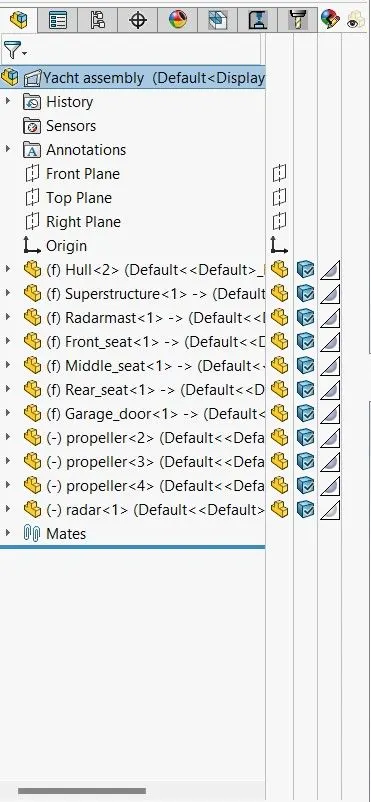
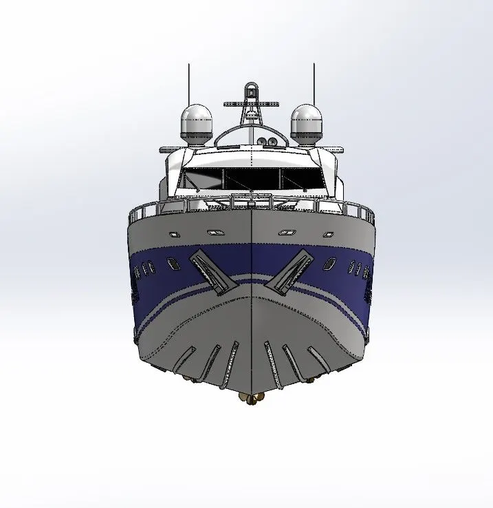
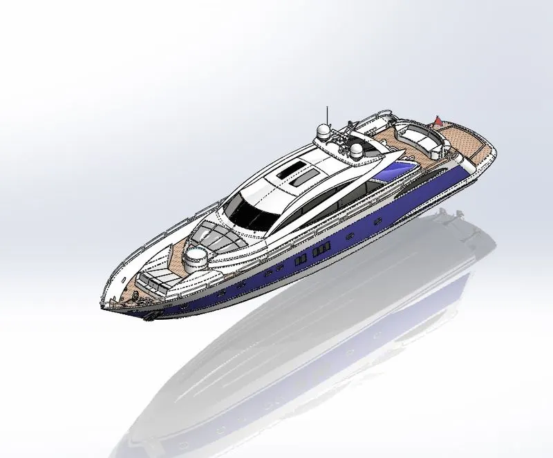
Yatch is assembled in the solidwokrs assembly workbench with proper features and tools.
Feature tree:
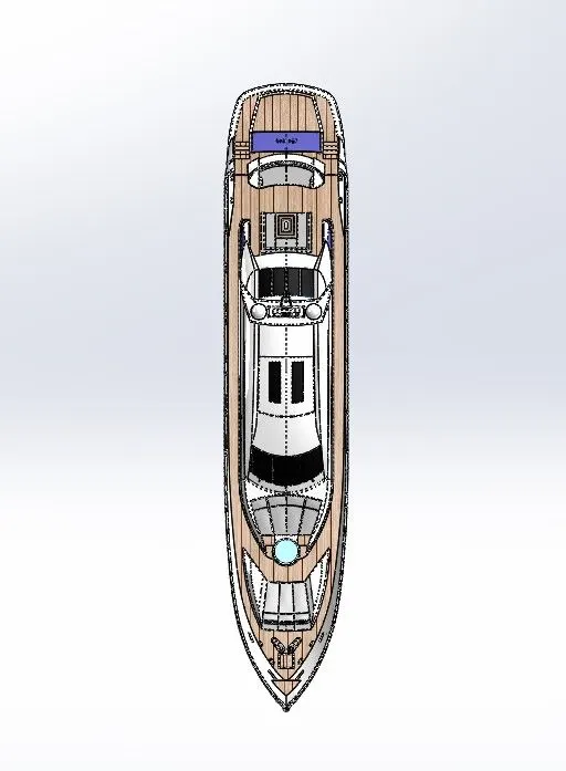
VIEWS:
Top view Left side view
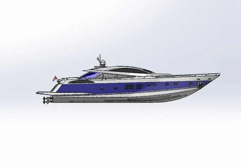
Front view Isometric view
RENDERING:
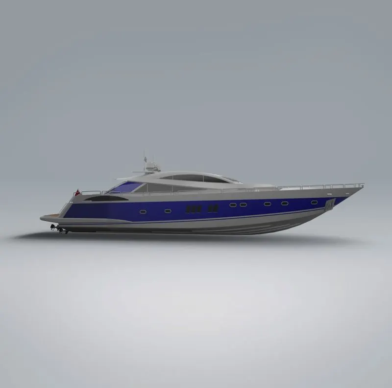
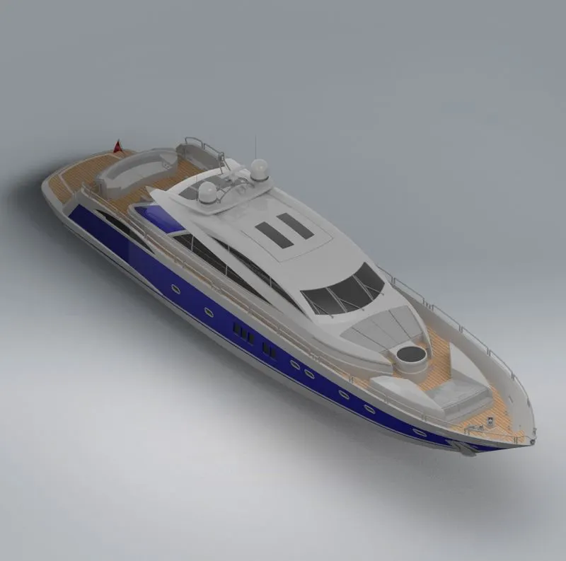
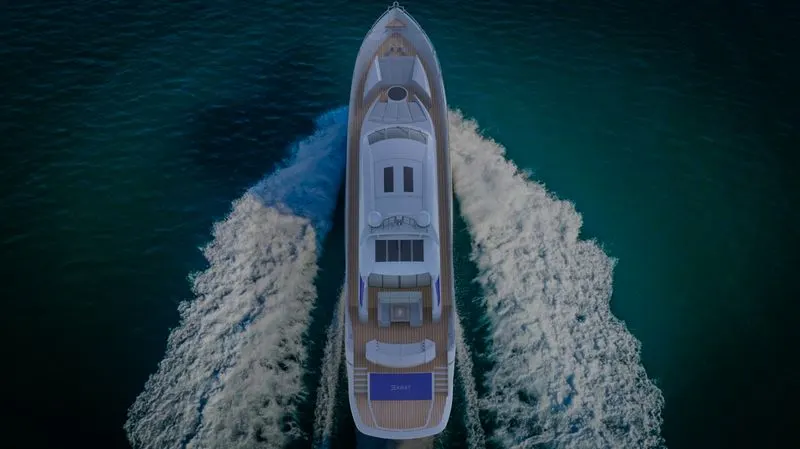
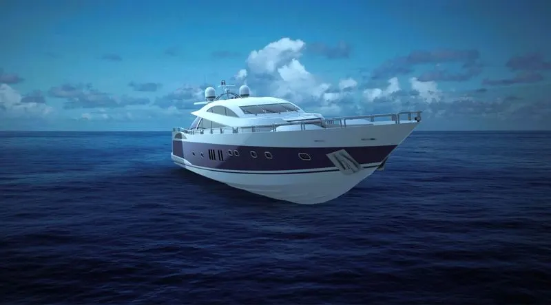
Rendering is the process of creating a raster image based on the 3D objects in a scene. A render is used to calculate the appearence of the materials attached to the objects in a scene, and how lighting and shadows are calculated based on the lights placed in a scene
PHOTOREALSTIC RENDERED IMAGES OF YACHT
STUDIO COMPOSTION:
Top View Front View
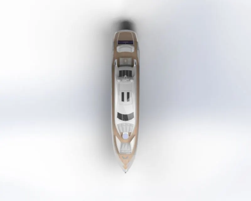
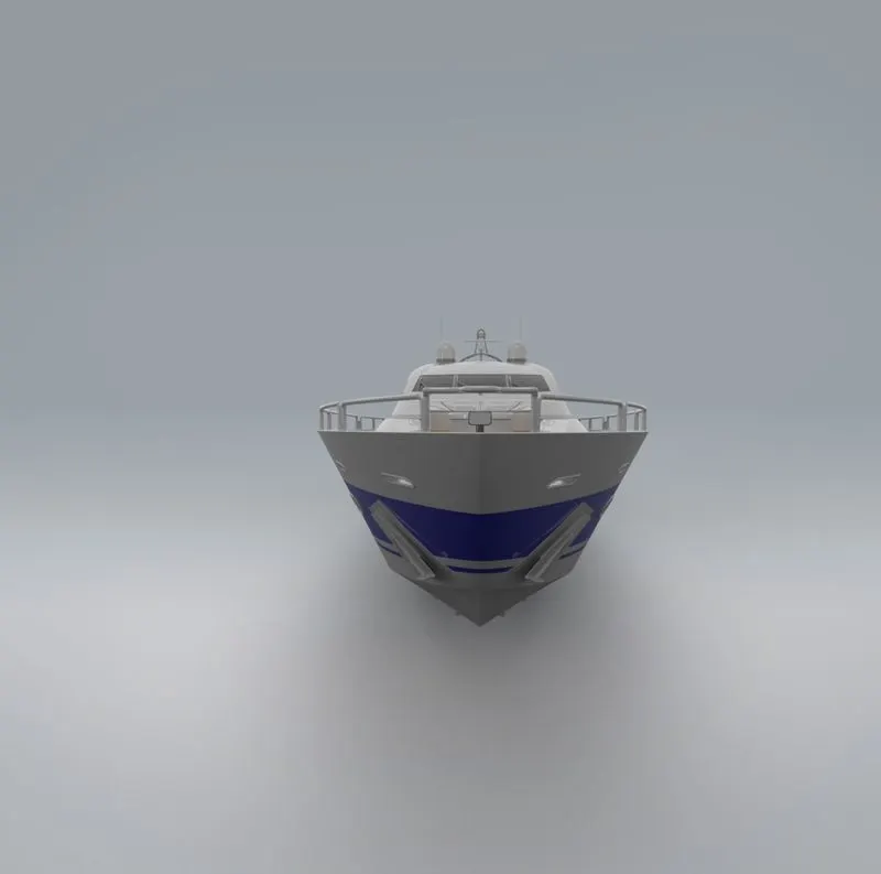
Side View Isometric view
SCENE COMPOSTION AND COLOUR GRADING:
CONCLUSION
All the parts of the Yacht were modelled and assembled using solidworks workbench and created an Photorealistic renders of the Yacht by using Solidworks visualize.