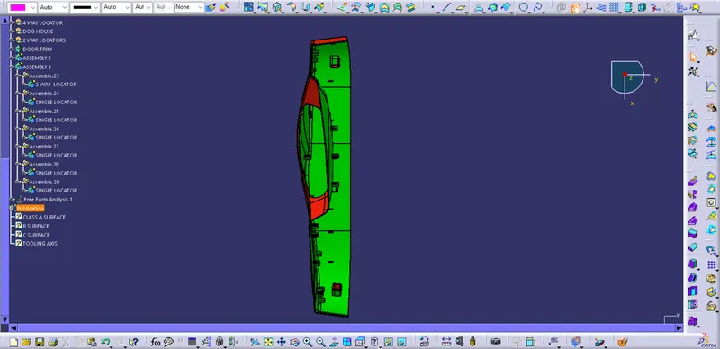
Week 9 - Project 1 - Door Trim Lower with Engineering Features
AIM
Create the Door Trim Lower Plastic component through the given Class-A surface. To begin with, the tooling axis for the given Class-A Surface should be created meeting the requirements of the draft angle and at the end perform the Draft analysis on the modeL.
THEORY
Engineering features are the extensions on the plastic components such as ribs, Screw bosses, heat stakes, locaters etc., which help fix the plastic component to the main surface and to avoid plastic defects while manufacturing the component through mould process.
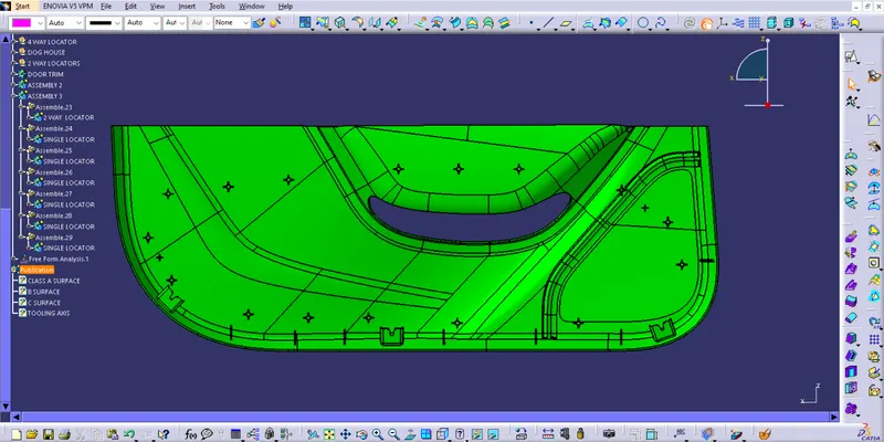
The features such as locators and heat stakes are to be added for the component shown below.
HEAT STAKES -
Heat Staking is a pulsed-heat process to join two or more parts out of which one at least is made of plastic. The process is to deform the plastic material using heat and force at a set process time. The bond is made by partially de-forming the plastic part in order to fix the other.
Heat Staking makes it easy to bond metal to plastic and is commonly used in high volume/low-cost applications such as automotive, IT and consumer appliances.
In Manufacturing Of thermoplastic components, it is often necessary to join the thermoplastic to a part of a dissimilar material, whether it can be a metal, dissimilar material or the other material. Thermal staking is an assembly method that uses the controlled melting and reforming of a plastic stud or boss to capture or lock another plastic or a metal component of an assembly in place. The plastic studs protrude through the holes in a component to be locked in a place. The heated thermal tip contacts the top of the stud, which melts and fills the volume of the tip cavity to produce the head, locking the component in a place. The progressive melting of the plastic under continuous pressure forms the head.
2 WAY AND 4 WAY LOCATORS -
In any kind of assembly before fixing the part to the mating part we need to fix the position of the part with respect to the mating part. In these cases, we need to follow some engineering principles. In this project we are going to follow the 3-2-1 Principle. Any Part which has to be fixed during welding or machining process has to be fixed is having 12 degrees of freedom.
Translation Movement along X Axis
Translation Movement along Y Axis
Translation Movement along Z Axis
Rotational Movement along X Axis
Rotational Movement along Y Axis
Rotational Movement along Z Axis
PROCEDURE
CREATING THE TOOLING AXIS USING BISECT METHOD:
- The first thing to do is finding out the possible tooling direction by visually checking the part. Rotate the part in all direction and find out the possible direction for tooling axis. Here in this case viewing from Z direction we can clear the face in tooling.
- Then we create a point on the surface of the part, we can create the point anywhere on the surface.
- Most of the cases we create the point in holes and pocket of the part.because the holes and pockets is to create a problems when we do the draft analysis.so we create a point in mid of the hole, to create a line on this point along z direction. named as DUMMY TOOLING AXIS. On this point we put a new axis system.
- Then we are finding out the tooling axis in X direction. For that intersect command is used to get the boundary in X direction.
BUT IN THIS CASE ALL FACES OF THE SURFACE ARE CLEARED WITH Y DIRECTION
First we extract a suitable surface
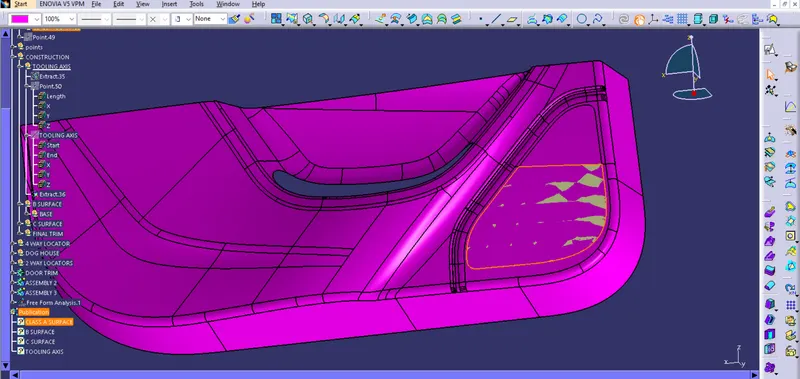
Creating point on the surface then creating tool axis using line tool.
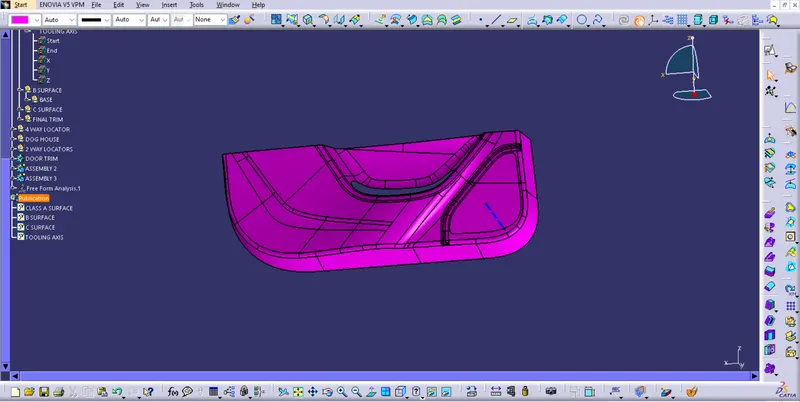
DRAFT ANALYSIS ON CLASS A
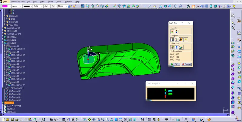
To perform draft analysis on the model:- Go to menu bar > select insert > Analysis > Feature Draft Analysis. To give the draft direction, use the compass and align Z-axis of it with the tooling axis. Once it properly aligned, lock the draft direction. A red point shown in the screen, select Base Bracket and it will show us the current of the model. Then go to display tab on draft analysis and select show Colour scale option and it will show the draft value. Set the Draft value to 3 deg under the colour scale variant and press ok.
CLASS B CREATION
Simply offsetting the Class A surface
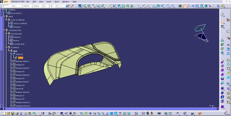
The offset surface have some defect . It is solved using Multi section surface tool , extrapolate ,multiple extract and sweep tools and last joining the newly created surface with offseted surface and Class B surface is created.
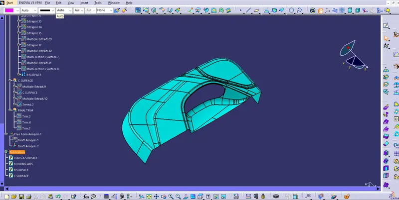
CREATING CLASS C SURFACE
First multiple extracting the outer edges after that sweep is applied by considering multiple extracte as guild curve, reference surface as Class A and angle of 90 degree.
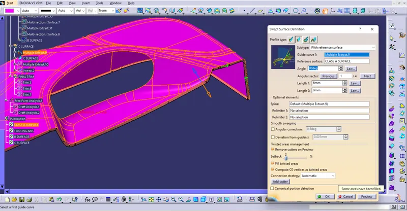
Sweep is also applied to the hole portion of the door trim. Finally Class C surface is formed.
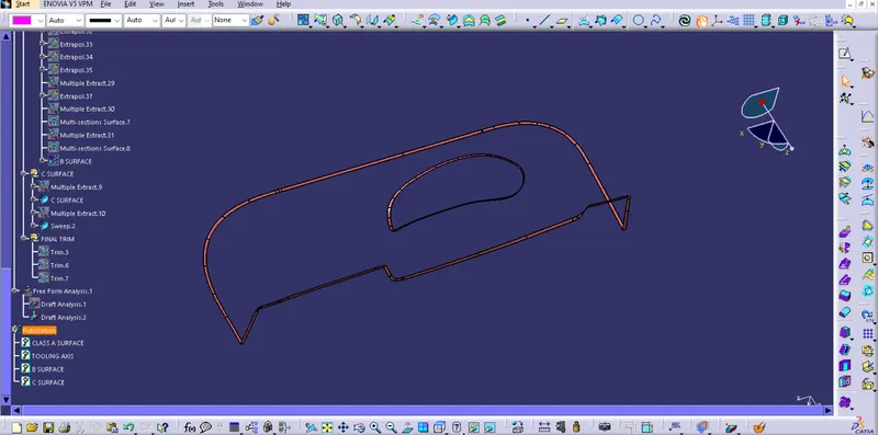
PART BODY CREATION
Class A, Class B and Class C surfaces are trimmed and the surface body is formed. It is convereted into solid body closesurface tool.
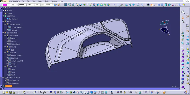
After this heat stakes, locators and dog house are created on the body.
DRAFT ANALYSIS ON FULLY DEVELOPED BODY
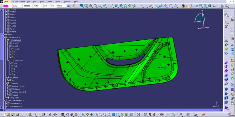
VIEWS
ISOMETRIC VIEW
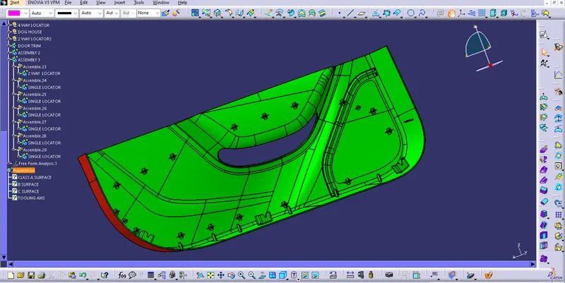
FRONT VIEW
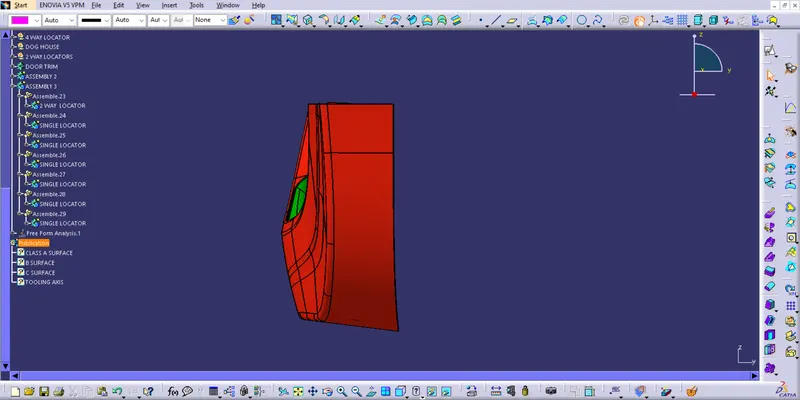
SIDE VIEW
TOP VIEW