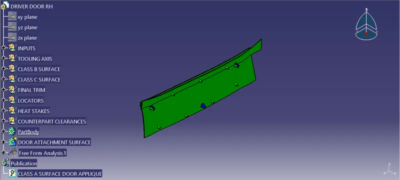
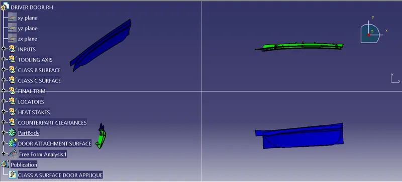
Week 9 - Project 1 - Door Trim Lower with Engineering Features
Objective:
- To create the tooling axis extract the base surface of Door Applique class A, create a point in centre and create a line normal to the surface and from the point and we would get the Tooling Axis
- To generate the Class B surface extract the Class A Surface faces individually untrim them - extrapolate and offset at a distance of 2.5mm
- And finally trim the unnecessary faces and provide fillets we would get the Class B Surface
- To obtain the Class C Surface create boundary for Class A Surface and sweep it with 3° draft till 10mm distance
- To obtain the final solid Door Applique plastic component trim the needless surfaces and join the class A,B & C surfaces together
- Then use closesurface command to form solid component
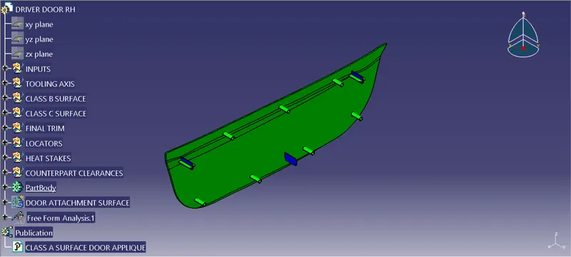
- For the creation of locators sketch the profiles for 4-way and 2-way locators and pad them with thick feature
- Provide 0.5° draft on their faces
- Give 3mm chamfer and fillets to the edges
- Copy-paste the locator part file and translate it to the desired location
- Unitrim the locator bodies with the solid Door Applique
- Similarly sketch the profile for heat stakes and pad them
- Provide 0.1mm and 0.5mm clearances for the locators and heat sinks respectively on the door attachment surface
Draft Analysis Report:
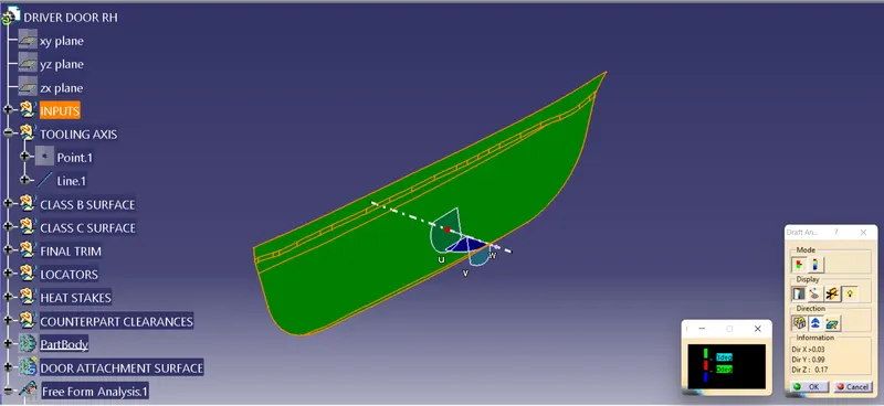
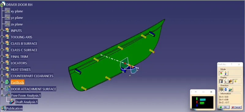
- We need to perform draft analysis on both the class A and solid component
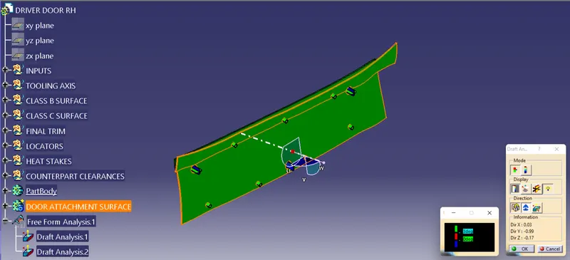
- For the draft analysis go to Insert-Analysis-Feature Draft Analysis and make sure the view mode is on material
- Inline the compass with the Tooling Axis and lock then click on the solid part we will get the draft analysis
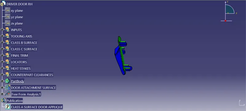
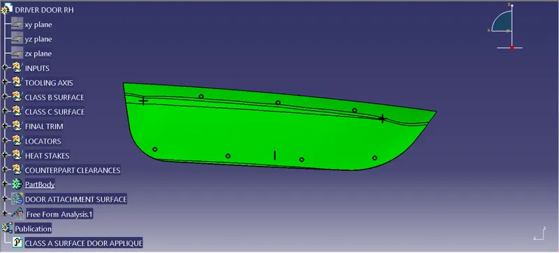
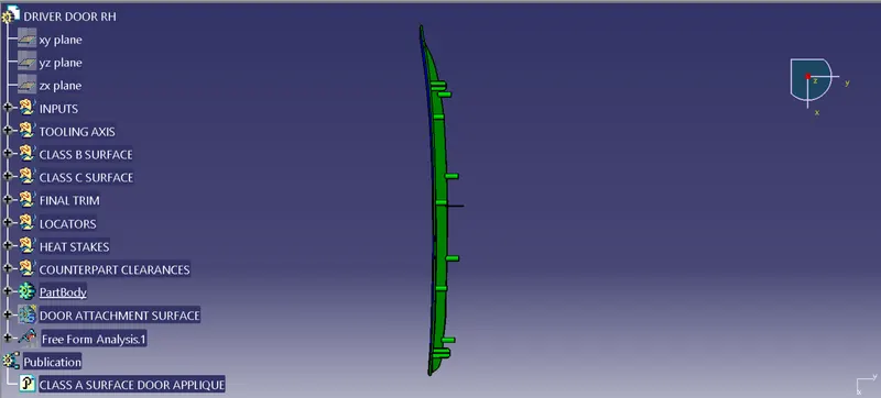
- When we click on the part it will turn green that means the required draft angle is maintained
- We can change the value of draft angle from the colour scale table and the model will change the colour accordingly
- We can also analyse the draft at a particular point on the body by moving the mouse cursor on the surface
Orientations: