Week 9 - Project 1 - Door Trim Lower with Engineering Features
Week 9 - Project 1 - Door Trim Lower with Engineering Features
Aim-Create the Door Trim Lower Plastic component through the given Class-A surface. To begin with, the tooling axis for the given Class-A Surface should be created meeting the requirements of the draft angle and at the end perform the Draft analysis on the model.
Create the Heat Stakes and the locators considering the design rules.
Procedure to be followed –
- Creating the Tooling Axis
- Draft analysis of Class A surface
- Creating Class B surface
- Creating Class C surface
- Creating Solid body
- Creating Engineering features heat stake and locators
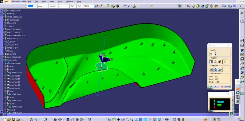
- Draft analysis of Solid body with engineering features.
Heat stake
The method of joining two different types of materials together is known as heat staking, commonly referred to as thermoplastic staking. In heat staking, we boost the temperature of plastic components and enable plastic reformation by using local heating and cooling. There are several uses for this reforming.
A broad variety of thermoplastic materials, such as polypropylene, ABS, polycarbonate, and many others, can be used for heat staking. The geometric connection between the boss and the thermal tip has a significant impact on the integrity of a thermal staked assembly.
Heat Staking reduces the need for additional hardware, which is susceptible to being damaged, breaking, or having other quality control problems. Hardware fasteners can frequently cost more and require more effort than heat-staking plastic fastening alternatives.
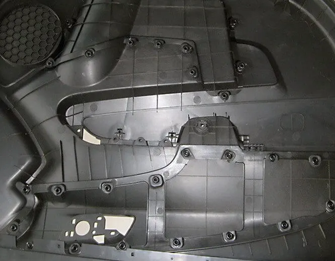
Locators
Workpiece can move in infinity number of direction. This motion can be classified into 12 directional of motion that is called Degree of freedom. For any component to be fixed in the particular we need to restrict these 12 degrees of freedom this is referred as 3-2-1 principle. Locators are used to restrict the degree of freedom.
2-WAY LOCATORS- A 2-way locating pin restricts motion along 1 axis (or 2 degrees of Freedom), like a round pin in a slot.
4-WAY LOCATORS- 4-way means you stop movement along two of the plane's axes (+X, -X, +Y, and -Y). Typically, you have a circular hole at the workpiece part and a cylindrical pin on the fixture.
- Creating the Tooling Axis
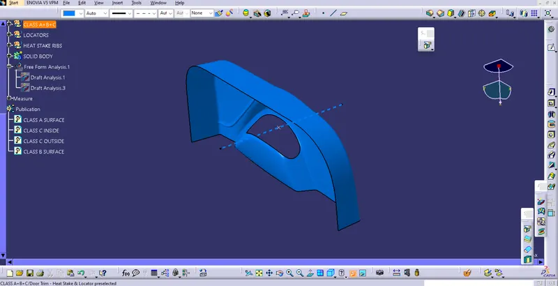
Tooling axis: The tooling axis determines the aperture of the cavity, core, or mould. By utilising the Boundary or Join function to identify and close the surface's open edges, you may first verify the connectivity of the given Class A surface.
Next, decide visually where the tooling axis should be located on a plane or surface. To locate the tooling axis, we must first extract the surface, mark a point, and then make the intersection. Draw a line at the intersection's edge and make a bisecting line to identify the tooling axis.
Draft analysis of Class A surface
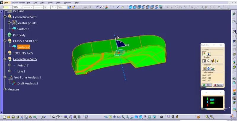
Once we received the class A surface from the designing team we need the check the componet is clearing the draft analysis or not if not then we need to report to the class A designer team to provide the required draft. The received model is clearing the draft analysis and it can be converted into the soild body.
Creating Class B surface
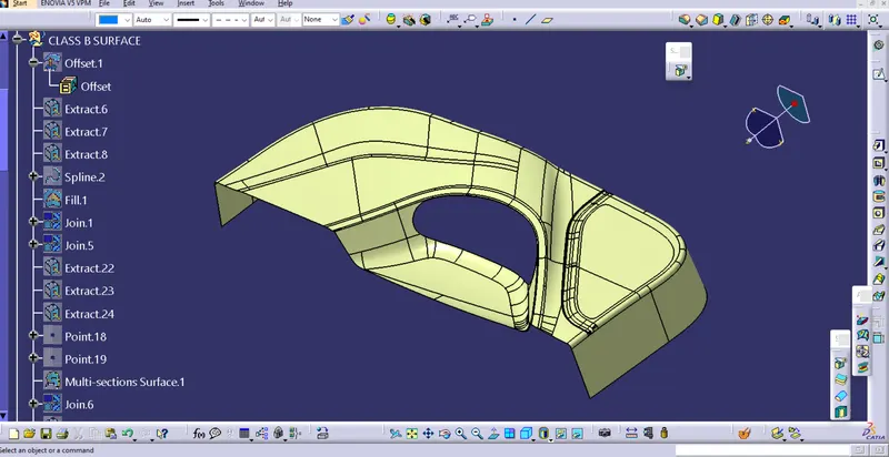
- To create the class B surface, we need to offset the surface of Class A. here we have given the offset value of 2.5 mm as per requirement. After giving offset we can se the some of the surface is not filled such as the portion of the fillets we need to fill those patches by multi section surface and some by extracting and trimming it.
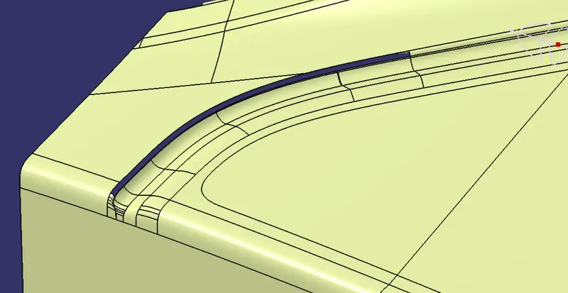
- If there are some patches left in the B surface as we can see the below image then we need tpo fill those patches using multisection solid comand
Class B surface
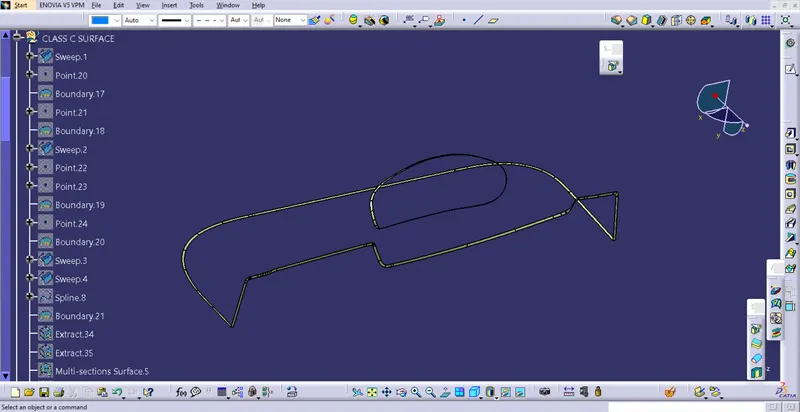
Creating Class C surface
- A Class C surface connects Class A and Class B surfaces. A Class C surface is created by the sweep command. By utilising the sweep command to establish the border of a class A surface at a 93 degree angle, we may produce a class C surface (Profile type: Line, Subtype: with reference surface).
- The A and C surfaces must first be combined with the C surface before being cut with the B surfaces.
Creating Solid body
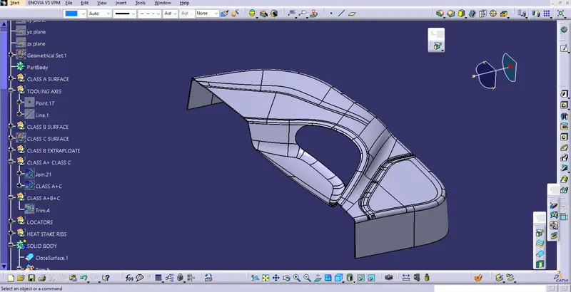
Creating Engineering features heat stake and locators
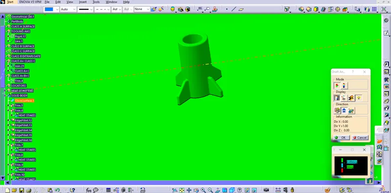
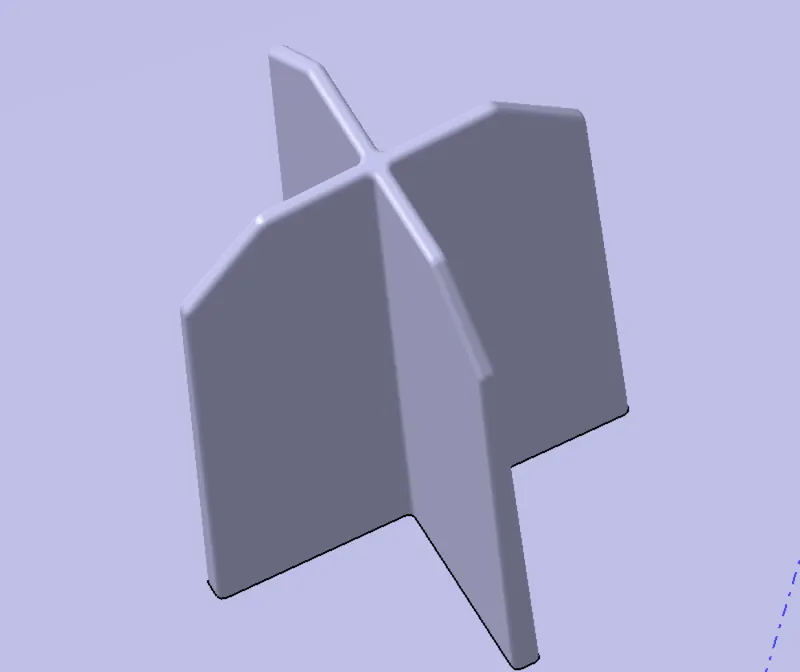
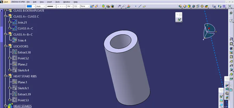
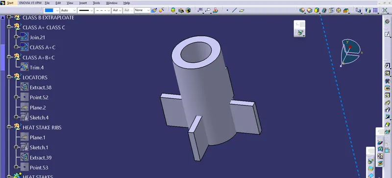
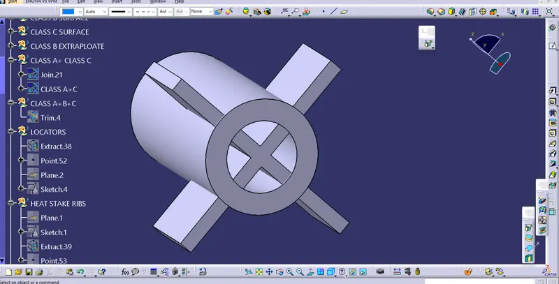
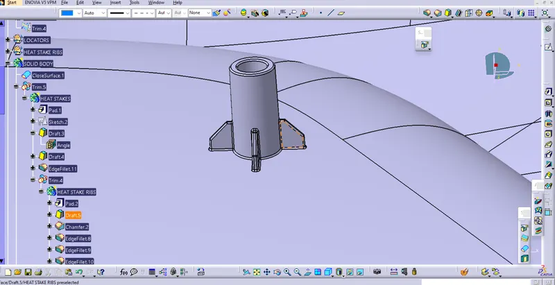
To create the heat stake we first took a plane parellel to curve and selected tooling axis as curve and point as a reference. I kept inner dia of heat skate as 5 mm and outer dia as 8 mm extruded to 15 mm and then created ribs and using boolena operation i removed the unwanted parts from two bodies.
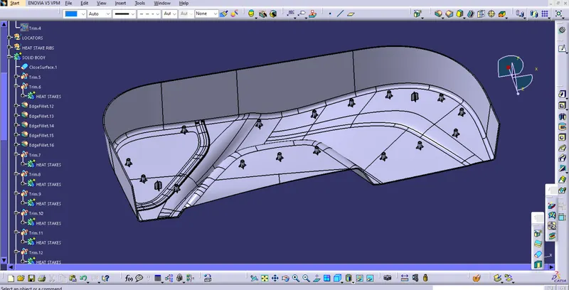
after that we need to translate the heat stake as perticular posiition for that we follow the below steps
- Copy the heat stake body
- paste in the main body using the paste spacle as a result with link
- select the translation option
- select point to point option
- select 1st point as origin point and 2nd point the where body is to be translate
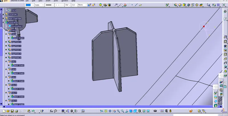
Locators - the height of the locators is kept 20 mm giving the draft of 0.5 degree and minimal fillet of 0.25 and translate in the same way as heat stakes
the below image shows the heat stake and locators
Draft analysis of Solid body with engineering features.
I utilised the included draft analysis tool in the part design workbench to conduct the draft analysis for the solid component body heat stake and locators. I first set the compass to point at the tooling axis, then I chose the solid component body and entered a 3 degree draft angle in the colour bar. As there are heat stakes and locators we can give draft 0.49 degree of draft to clear the draft analysis.