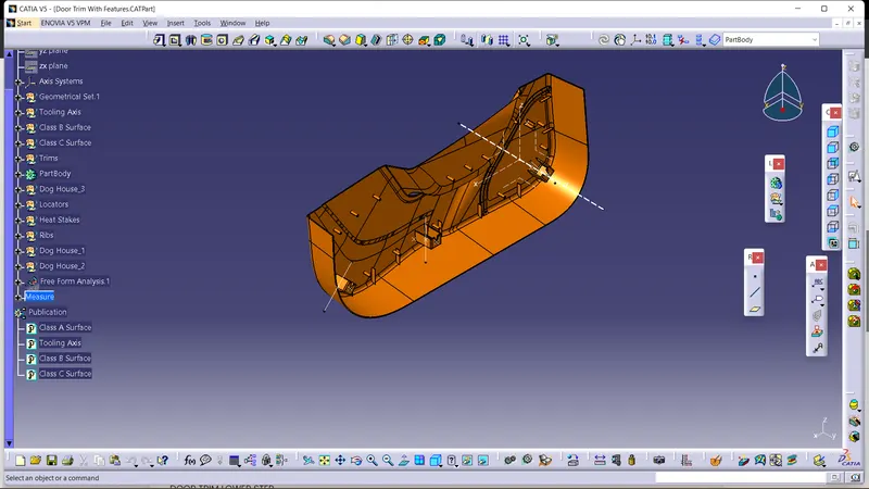
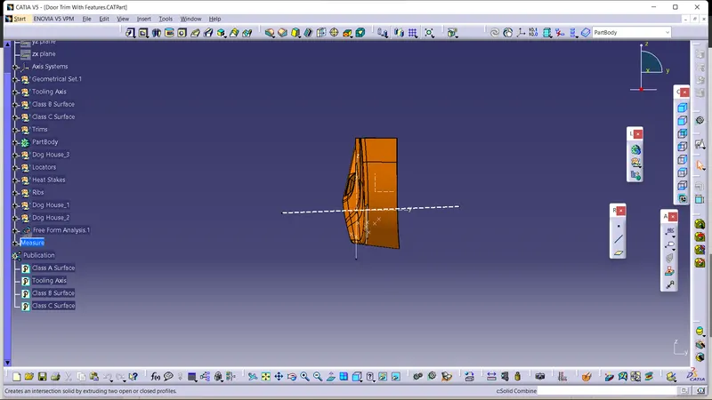
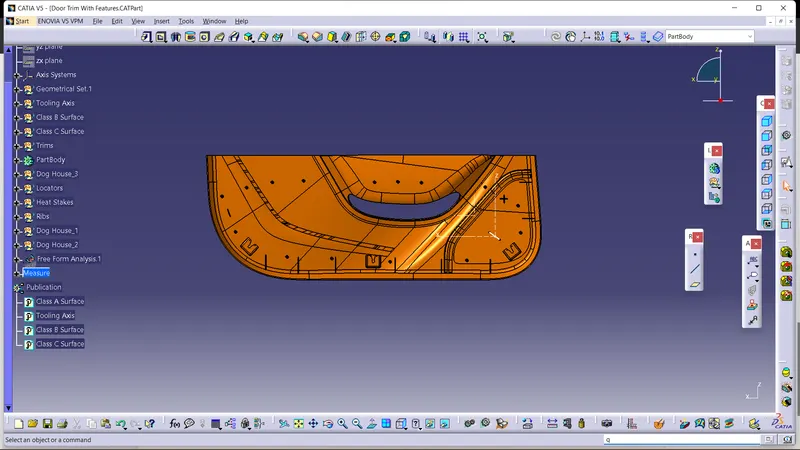
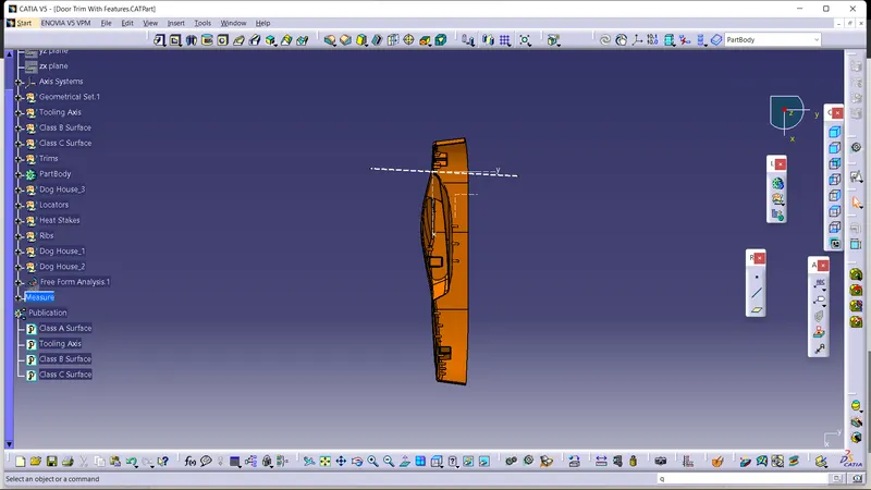
Week 9 - Project 1 - Door Trim Lower with Engineering Features
Tooling Axis -
It is Axis along which the core and cavity move.
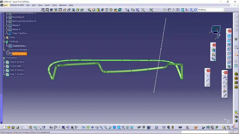
To make the tooling axis, we need to take the intersection of the part. The plane is used to find the intersection curve. Then it is looked for the curve elements which can possibly create problems while ejecting the part. The curves which are almost perpendicular or have a high angle with the tooling axis can create no problem as they can be easily ejected. On the other hand, if the intersection curve has some elements which are almost parallel or has a small angle with the tooling axis, lines are created through them and the bisecting line is used to create the tooling axis.
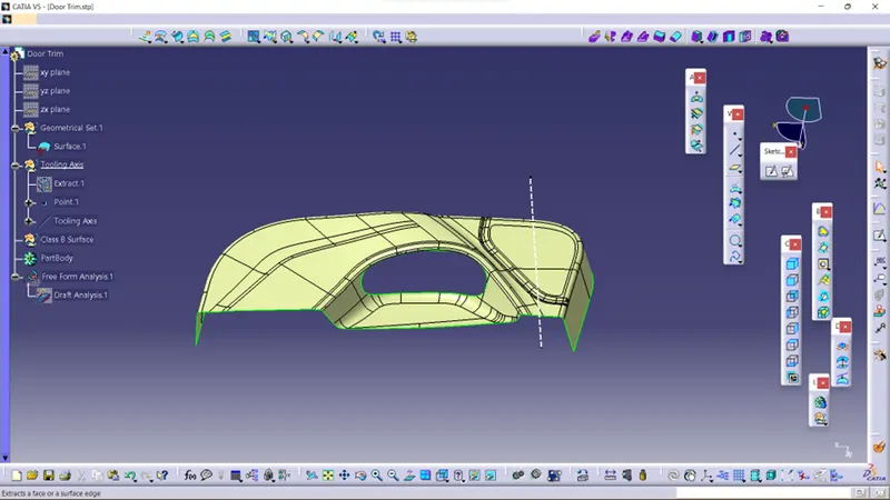
Here the tooling axis is created on a flat surface and elements have a higher angle with the tooling axis. It is considered the main tooling axis.
Class A Surface -
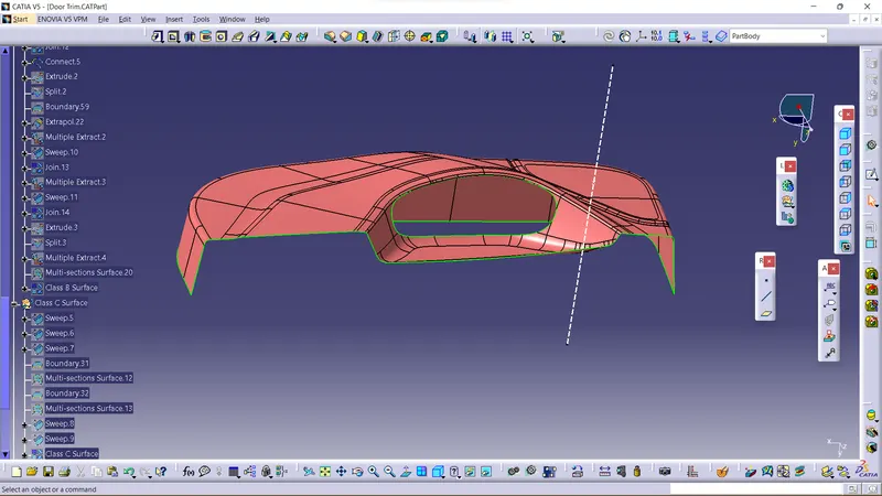
Class A surface is an Aesthetic Surface that is visible to the customers. This Surface is Created in Solidworks Alias software.
It is provided as Input for Component creation.
Draft Analysis -
Draft Analysis allows the designer to analyze whether the given or created part has proper draft angles or not. Draft angles are the amount of taper for the parts Perpendicular to the parting line.
Draft Analysis Before -
An analysis is performed on the Class A surface to check if the surface is provided with proper Draft angles.
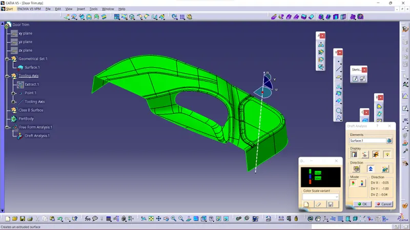
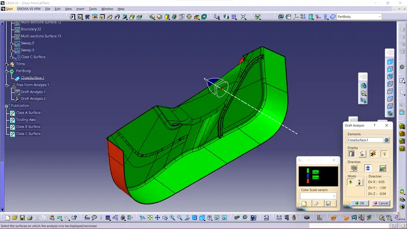
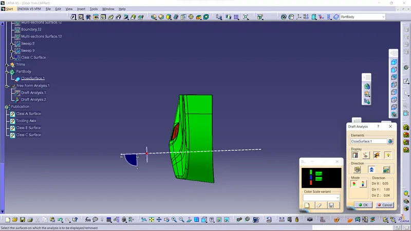
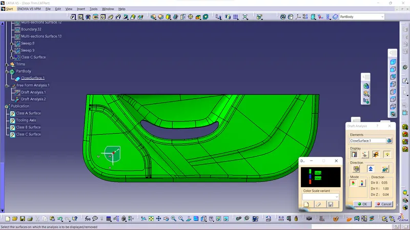
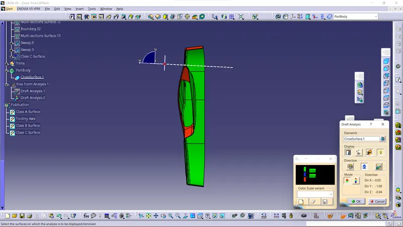
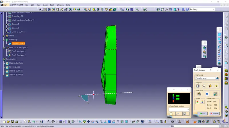
Draft analysis is performed in the following manner - go-to tools > analysis > Feature Draft Analysis. This tool has three groups of options namely; mode, display, and direction. First, the second icon from the direction group is selected and the red dot in the compass is clicked and dragged to the part to be drafted. The line in the dragged element is matched with the tooling axis and it is locked using the first icon in the direction group. It will define the tooling axis direction and lock it. Then click the base bracket. It will turn green and red based on the draft angles. If the minimum draft angle is set to 3, it will turn green; otherwise, it will turn red, Thus, the draft analysis is complete.
The analysis is done for a 3-degree draft. The below image shows all the surfaces are more than 3deg.
Class B Surface -
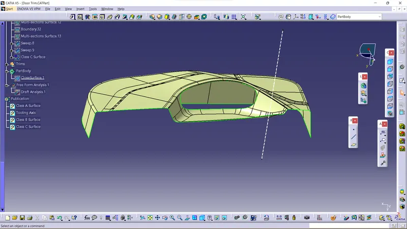
Class B surfaces are the surfaces that are created from Class A surfaces but are not visible to enduser.
All the features are provided on this surface.
Below is the image of the Class B Surface with proper fillets.
Class C Surface -
Class C surface has more imperfection than Class A or Class B surface.
These surfaces are not readily visible, they are covered by another part or are the link between the other two surfaces, these do not need to have a high finish or aesthetics.
The below image shows the Class C surface.
Draft Analysis -
Part Body -
Solidified part body of the component with all features.