Week 9 - Project 1 - Door Trim Lower with Engineering Features
AIM :
Create the Door Trim Lower Plastic component through the given Class-A surface. To begin with, the tooling axis for the given Class-A Surface should be created meeting the requirements of the draft angle and at the end perform the Draft analysis on the model.
Create the Heat Stakes and the locators considering the design rules .
INTRODUCTION :
- Heat Staking
Heat Staking is a pulsed-heat process to join two or more parts out of which one at least is made of plastic. The process is to deform the plastic material using heat and force at a set process time. The bond is made by partially de-forming the plastic part in order to fix the other.
Heat Staking makes it easy to bond metal to plastic and is commonly used in high volume/low cost applications such as automotive, IT and consumer appliances.
In Manufacturing Of thermoplastic components,it is often necessary to join the thermoplastic to a part of a dissimilar material,weather it can be a metal,dissimilar material or the other material.Thermal staking is an assembly method that uses the controlled melting and reforming of a plasticstud or boss to capture or lock another plastic or a metal component of an assembly in place.The plastic studs protrude through the holes in a component to be locked in a place.the heated thermal tip contacts the top of the stud ,which melts and fills the volume of the tip cavity to produce the head,locking the component in a place. The progressive melting of the plastic under continous pressure forms the head.When Staking,the right combination of heat and pressurefor the applications is critical.
Heat Staking makes it easy to bond metal to plastic and is commonly used in high volume/low cost applications such as automotive, IT and consumer appliances.
The plastic is deformed by heating it to a temperature above the glass transition temperature. Super-heated air or a thermode is used for this. Pressure is then applied to create the stake. After the stake has been formed, the plastic should be cooled down again below the glass transition temperature. Cooling is performed under constant pressure to ensure good fixation of the parts. Compressed air can be applied for cooling when a thermode is used.
Heat is used to facilitate the creation of the stake. Heat control is critical, especially for glass-filled plastics which often have a process window of less than 10 degrees Celsius. When the temperature is too high, the glass fibers come out of the plastic which leads to a rough surface and adhesion to the thermode. If the temperature is too low, the plastic will crack due to cold deformation.
Advantages of Heat Stakes:
- Similar and dissimilar materials may be joined: metal to metal, plastic to plastic, metal to plastic.
- Accurate control operating within a small process window.
- Local heating resulting in no damage to surrounding materials.
- Processing of glass-filled materials.
- No mechanical vibration.
- Many heat-stake shapes possible through custom designed tools.
- 2 and 4 way locators
In any kind of assembly before fixing the part to the mating part we need to fix the position of the part with respect to the mating part. In these cases we need to follow some engineering principles. In this project we are going to follow the 3-2-1 Principle. Any Part which has to be fixed during welding or machining process has to be fixed is having 12 degrees of freedom.
- Translation Movement along X Axis
- Translation Movement along Y Axis
- Translation Movement along Z Axis
- Rotational Movement along X Axis
- Rotational Movement along Y Axis
- Rotational Movement along Z Axis
PROCEDURE:
1) Input Given
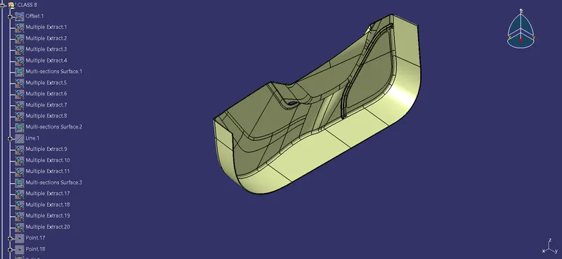
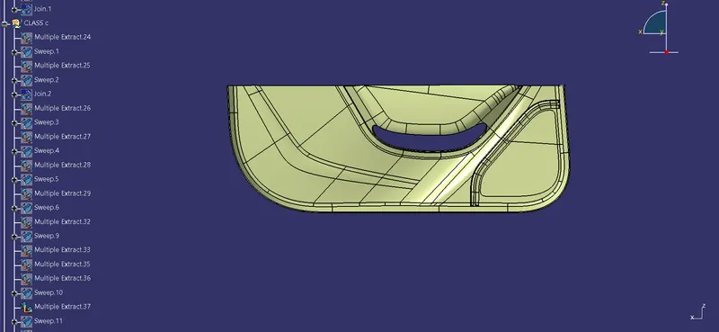
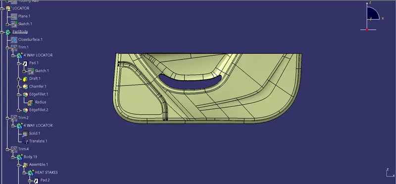
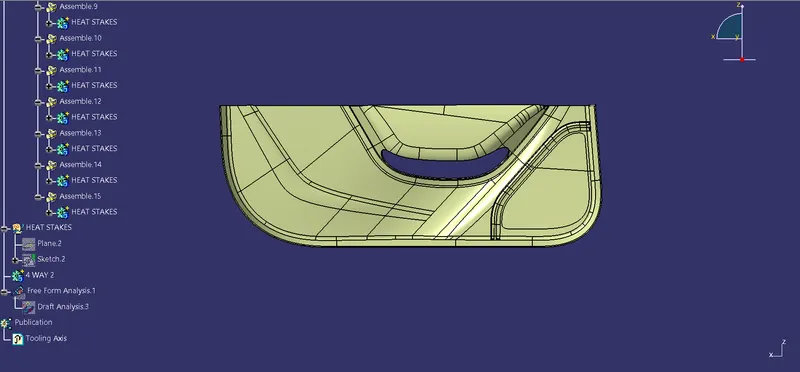
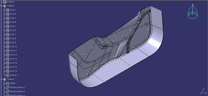
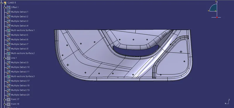
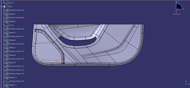
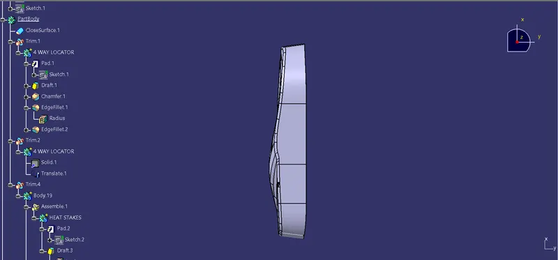
2)Tooling Axis
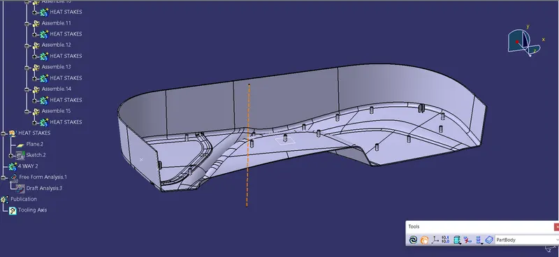
Tooling axis is nothing but the direction in which the core and cavity opens and closes. Design engineer works is to analyse the Class A surface and find out the best possible tooling direction keeping in mind all the draft angle is with respect to the tooling axis so that the component can be easily ejected from the moulds.
1) The first thing to do is finding out the possible tooling direction by visually checking the part. Rotate the part in all directions and find out the most suitable direction for tooling. Here in case of this part viewing from Y direction, we can clear the face in tooling.
2) Then we create a point on the surface of the part, we can create the point anywhere on the surface but usually, we take CG point or take a point near to the center. On this point, we put a new axis system.
3) Then we are finding out the tooling axis in Y direction.
3) A Class Surface
In automotive design, a class A surface is any of a set of freeform surfaces of high efficiency and quality. Although, strictly, it is nothing more than saying the surfaces have curvature and tangency alignment – to ideal aesthetical reflection quality, many people interpret class A surfaces to have G2 (or even G3) curvature continuity to one another. Class A surfacing is done using computer-aided industrial design applications. Class A surface modellers are also called "digital sculptors" in the industry. Industrial designers develop their design styling through the A-Surface, the physical surface the end user can feel, touch, see etc.
4) B Class Surface Creation
Represent internal and/or functional surfaces. This cluster exemplary includes derived surfaces created by offset operations from class A surfaces to define the thickness of material. In this file it is important to link class B surfaces geometrically to enable an adaptation to class A surfaces automatically in case of styling change.
After creating the tooling axis, B surface is to be created which is nothing but the surface parallel to the A surface. B surface contains all the fillets and the edges which the A surface contains.
5) C Class Surface Creation
Class C Surface is swept along the boundry of the Class A at an angle perpendicular to the CLASS A surface with respect to the tooling axis direction with a draft angle of 3 degree.
C surface is the thickness side of a part which joins the A surface and B surface.
1) First create the boundary line of the A surface.
2) Then using the Sweep command make the side surface with draft.
3) In Sweep using the Line option. For Subtype select "With Draft Direction"
4) For Guide Curve1 Show the Boundary of A surface.
5) Draft direction show the tooling axis.
6) For Angle give 3 degree and Length of 5mm.
7) Then use trim option to trim the unnecessary surface. And join A,B and C surface to form a Closed surface.
8) Go to Part Workbench and make a solid part with the closed surface.
7) Draft Analysis
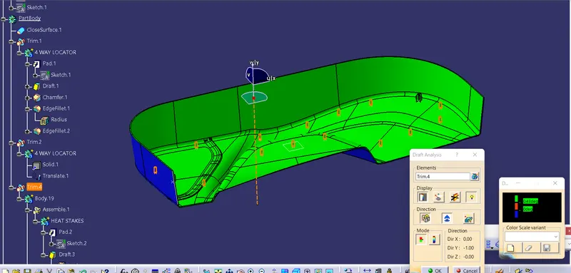
The Draft Analysis command enables you to detect if the part you drafted will be easily removed. This type of analysis is performed based on color ranges identifying zones on the analyzed element where the deviation from the draft direction at any point, corresponds to specified values.
Draft angles are very important in thermoforming product design. If the product is formed onto a female or negative mold, it shrinks away from the mold sidewalls. As a result, true female or negative products can be thermoformed with vertical walls having zero draft angles.
8) Creating 2 and 4 way locators and Heat stakes :
4-way locators mean you prevent movement at 2 axis (+X, -X, +Y and -Y) on the plane. Generally you have cylindrical pin on the fixture and circular hole at workpiece part.
2-way locators mean you prevent movement only at 1 axis on the plane.
While creating the locators we need to follow the design rules to create the ribs in order to avoid the sink marks on the components.
Heat Staking is a pulsed-heat process to join two or more parts out of which one at least is made of plastic. The process is to deform the plastic material using heat and force at a set process time. The bond is made by partially de-forming the plastic part in order to fix the other.
Once done with the design of locators and the heat stakes we need to design the counter holes in the mating parts with standard clearances as shown in picture below.
CONCLUSION:
- Thus the Door Trim id developed by using given Class A surface .
- 4 Way locators has been designed in order to fix the position of the applique with the mating door panel and also designed the heat stakes which used to fix the component with the mating panel by melting.