Week 9 - Project 1 - Door Trim Lower with Engineering Features
Create the Door Trim Lower Plastic component through the given Class-A surface. To begin with, the tooling axis for the given Class-A Surface should be created meeting the requirements of the draft angle and at the end perform the Draft analysis on the model.
PROCEDURE:
- Verify Class A
- Tooling axis
- Draft analysis on Class A surface
- Creating class B surface
- Creating class C surface
- Joining class A and class C
- Final trim of class B with class A and class C
- Check the boundary for the final close surface
- Perform the closed surface operation on the final surface
- Conduct the draft analysis on the close body
- Publish the final tooling axis class A, B, and C surfaces, closed surface, part body, and final draft analysis
- Conclusion
- CLASS A SURFACE:
In automotive plastic design, a class A surface is any set free from high efficiency and quality surfaces. Class A surfacing is done using a computer-aided industrial design application design engineers develop their design styling through the A-Surface software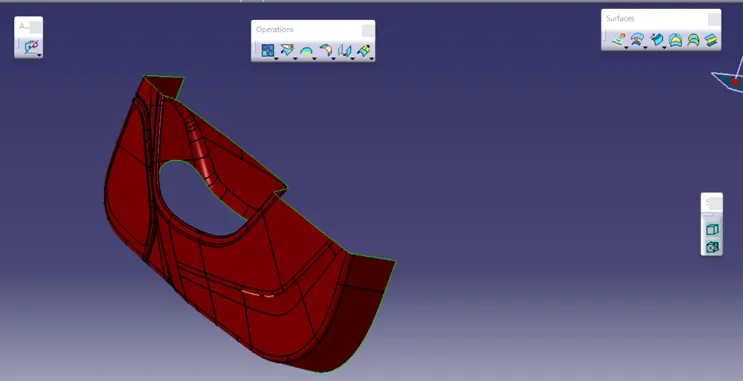
Design check on Class A Surface:
After receiving class a for the door trim check for the connectivity of the surface on it. If there is any disconnectivity, use joins operation, multiple extracts, multi-section surface, boundary operation, and disassemble. Perform the Join operation to join the dis-connectivity of the surfaces and merging distance =0.003mm. Once again, check the Class A surface for disconnectivity and proceed further for the tooling axis.
- TOOLING AXIS:
It is the direction in which the mold or core & cavity open. Part drafts are given along this axis.
Tooling operation:
To decide on the tooling axis, the component should be completely clearing the Tooling axis in the given specific direction.
The first one visually checks. We can check, which one is possible for Tooling Direction. We can check all x, y & z directions. If you have a hole, what will happen, you have a separate side core for a specific hole. In this draft analysis of door trim Z – direction the possible Tooling direction and tooling axis are created by bisecting method.
- DRAFT ANALYSIS:
Procedure:
- Change view mode
- Customize view parameters.
- Choose the material in the shading option.
- Use the draft analysis option for class A surface and Tooling Axis.
- Go to INSERT – ANALYSIS – FEATURE DRAFT ANALYSIS.
- Place the compass on the tooling axis, lock the direction, and then left-click on the class A surface.
- Change the angle to minimum draft angle i.e, 3 degrees as per requirements.
- Find the color grading on the surface to avoid errors in the draft angle.
- CLASS B SURFACE:
Offset the class A surface to the thickness value [2.5mm] to get B Surface. It is a surface it gives thickness from Class A Surface, all the engineering features like screw boss, ribs, heat stacks, and other supporting features could be formed on the B Surface. Class B Surface know as Engineering Surface.
Surface operation:
- To create the thickness of the class A surface along with the following steps.
- To create B surface area offset class A with 2.5mm.
- Perform multisection surface and sweep operation on the required door trim class b surface patch.
- CLASS C SURFACE:
The purpose of Class C surfaces is to connect Class A surfaces & Class B surfaces. It gives the thickness of the model.
Surface operation:
- Perform sweep operation to create some thickness of profile with the draft angle of 3 degrees and draft direction is the tooling axis.
- Sweep class C surface more than the thickness and the extra surface can be trimmed
- JOINING OF CLASS A and C: Perform the joining operation with 0.003 on the class A and C so that it can trim the class B surface to get the closed surface.
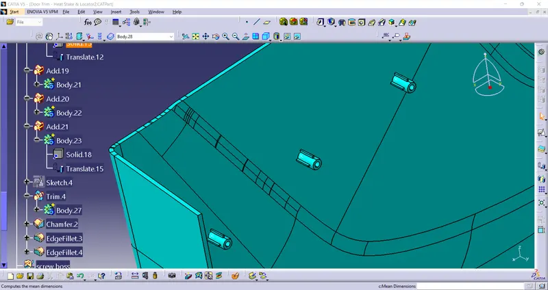
- TRIMMING OF CLASS A and C WITH CLASS B:
To get the closed surface as the thickness model we need to perform trim operation Class B with the final joining of Class A and C. before performing the trim operation check the intersection between the class B and joined surface of class A and C to know the disconnected points which are displayed in black.
8 . BOUNDARY OPERATION:
BY performing boundary operation we can able to find the open surface, if the final surface does not have any opening then boundary operation cant is performed thus it final surface is completely a closed surface.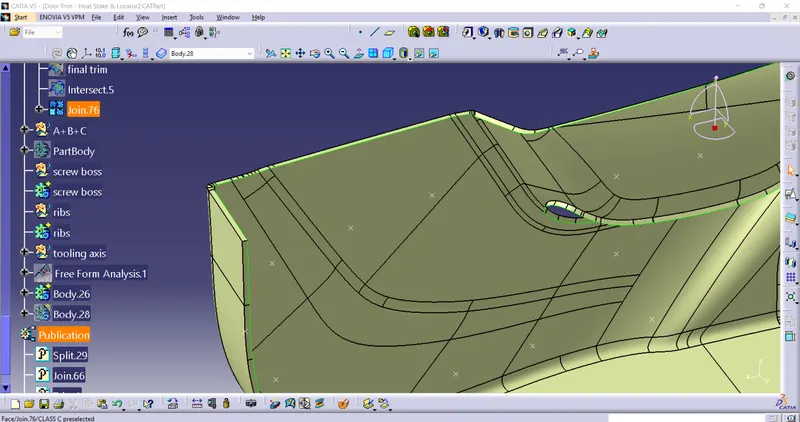
- CREATING THE SOLID COMPONENT:
Step to create a solid component from a closed surface
Go to part modeling & click the close surface option it creates a complete model of the surface.
CONCLUSION: Obtained Heat Stakes and the locators on the door trim of the solid component from the class A surface by following the procedure