Photo Realistic Rendering
MODELING AN AMERICAN CHOPPER AND ITS COMPONENTS USING THE SOLIDWORKS SOFTWARE
OBJECTIVE:
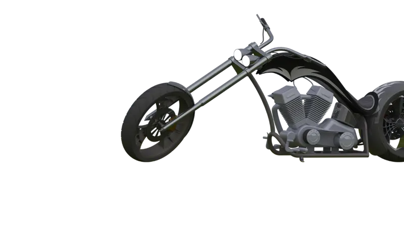
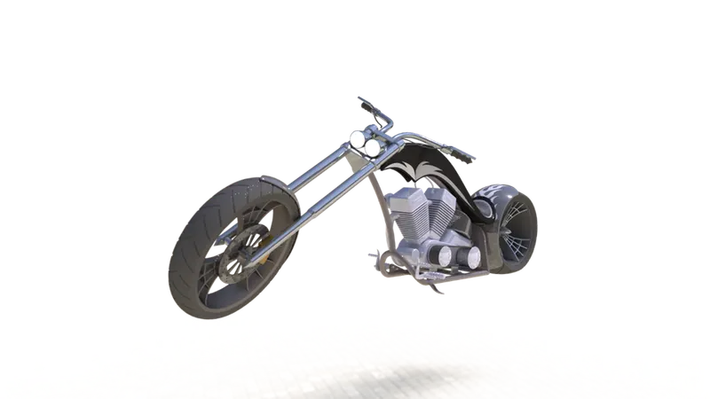
To create a model of an American chopper bike using solid works and some rendered images of the bike.
INTRODUCTION:
This is a project report about designing the American chopper bike components and assembling them using Solidworks software.
METHODOLOGY
PLAN OF ACTION FOR DESIGNING CHOPPER:
- Designing and modeling various components/parts
- Assembly of components/parts
- Setting up camera, environment, lights, etc
- Final rendering, realistic model images
Various Tools and features used to model the parts are as follows:
- 2D Sketch: A 2D Sketch is a base to create a 3D model. It is created on the plane on 2 axes. Various line tools, circles rectangles, splines, etc, are mainly used to create sketches, tools such as power trim, trim extend, etc. were widely used in this project.
- Projected curves: A Sketched curve onto a model face to create a 3d curve. It can be also created by creating sketches on two intersecting planes.
- Trim: is a tool used to remove the extra edges of intersecting lines on a 2D sketch.
- Offset: Used to add sketch entities by offsetting faces, edges, curves, etc to a specified direction and distance.
- Convert entities: convert the selected model edges or sketch entities into the current sketching plane.
- Boss extrude: it is used to extrude a sketch or selected contours in specified directions thus creating a solid feature.
- Revolved boss: revolves around a sketch or selected sketch contours about an axis, thus forming a solid feature.
- Swept boss sweeps a closed profile along an open or closed path to create a solid feature.
- Extruded cut: it removes material from a 3D model according to the selected profile along a specified direction.
- Revolved cut: it removes material from the 3D model according to the selected profile about a specified axis.
- Loft: the loft feature helps to create shapes by making transitions between multiple profiles and making use of guide curves to form complex geometry.
- Dome: A dome is a smooth rounded vault forming the outside face of a body or structure.
- Fillet: used to connect adjacent faces with a specified tangent curve.
- Chamfer: used to connect adjacent faces with a specified inclined line.
- Combine: it is used to combine two or more solid bodies.
- Extended surface: Used to extend the selected edge of a surface along a specified direction and distance.
- Lofted surface: it is used to create a lofted surface between two more profiles.
- Shells: used to hollow out a part, leaves open the faces we select and create thin-walled features on the remaining faces, and create thin-walled features on the remaining faces.
- Assemblies: Used to build complex assemblies consisting of many components which can be parts or other assemblies called subassemblies.
DESIGNING VARIOUS COMPONENTS/PARTS:
The America chopper bike consists of 13 parts:
- Transmission Belt
- Kickstand
- Chain
- Rear fender
- Rear wheel
- Front wheel
- Front fender
- Pedal
- Oil tank
- Front fork
- Chassis
- Engine
- Gas tank
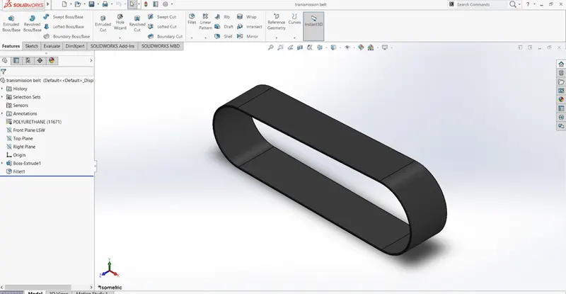
- TRANSMISSION BELT:
The main function of the transmission belt is to transmit power from the engine to the gear box. The features used to modelling the transmission belt are,
- Spline tool
- Fillet
- Extrude Boss/Base
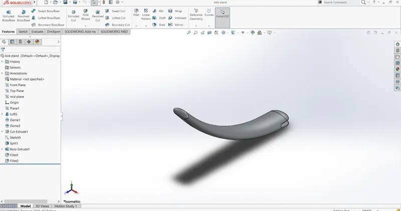
- KICKSTAND:
A kickstand allows the bike to stand upright without any external support. The features used for modelling the kickstand.
- Loft
- Extrude
- Dome
- Split
- Fillet
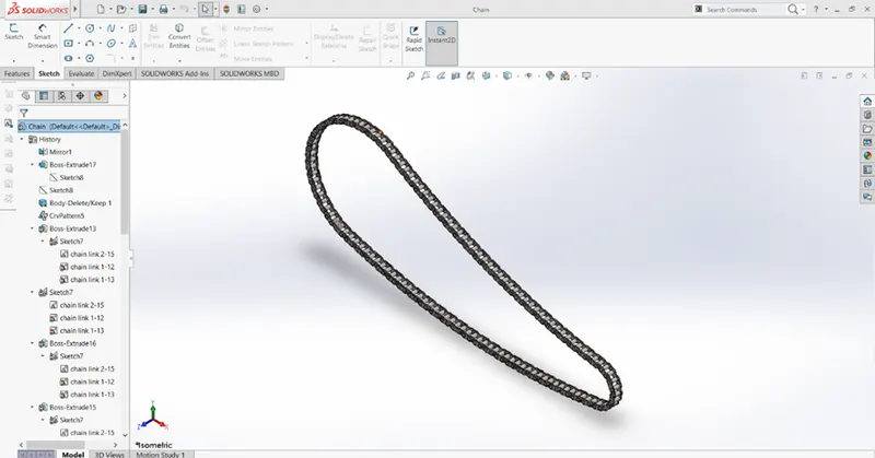
- CHAIN:
The chain is used to transmit power from the engine to the rear wheel through sprockets. The features used for modeling the chain are,
- Blocks
- Extrude
- Pattern
- Mirror
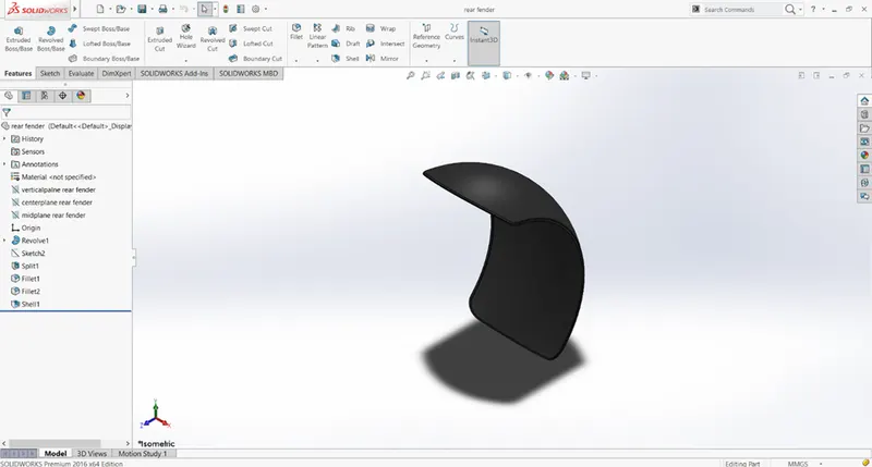
- REAR FENDER:
The fender is used to prevent mud and dust from being wheel-thrown towards the rider. Basically its acts like a safety device for the bike, the features uses
- Revolve
- Split
- Fillet
- Shell
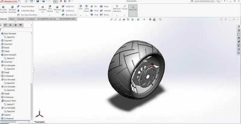
- REAR WHEEL:
The rear wheel is the powered wheel in the bike. It propels the bike. The features used for modelling the rear wheel are,
- Revolve
- Extrude
- Pattern
- Combine
- Fillet
- Chamfer
- Front wheel:
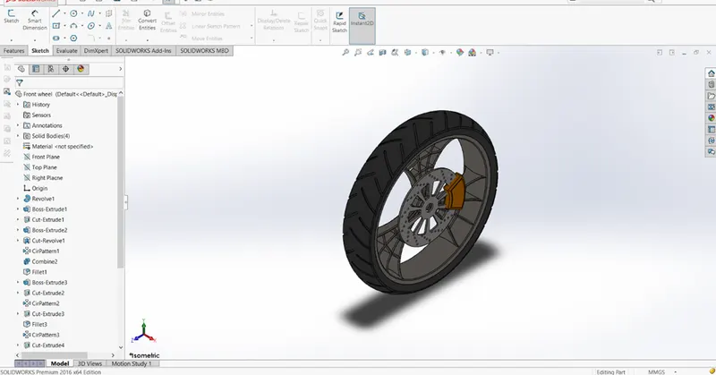
The front wheel helps to turn the vehicle while moving. The features used for modelling the front wheels are
- Revolve
- Extrude
- Fillet
- Pattern
- Chamber
- FRONT FENDER:
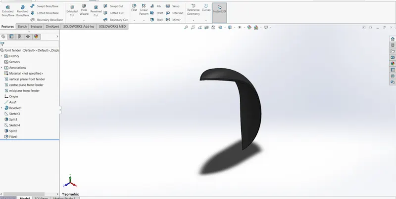
Front-wheel helps to turns the vehicle while moving.the features used for modelling the front wheel are,
- Revolve
- Extrude
- Fillet
- Pattern
- Chamfer
- Pedal:
The pedals are used to operate brakes or switch gears in the vehicle. The features used for modelling the pedal are,
- Extrude
- Fillet
- Dome
- Chamfer
- pattern
9.OIL TANK:
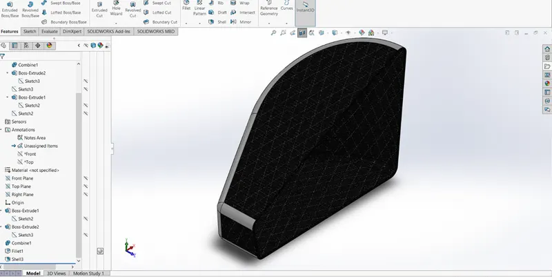
Oil is use to store the oil in bike. The features used for modelling the oil tank are,
- extrude
- combine
- fillet
- shell
- FRONT FORK:
The front fork connects the wheel and axle to the vehicle chassis . the features used for modelling the front fork are,
- Revolve
- Extrude
- Pattern
- Dome
- Fillet
- Sweep
- Projected curve
- Combine
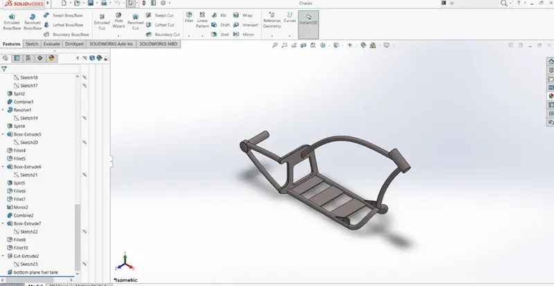
- CHASSIS:
The chassis is the supporting frame of a vehicle on which various components of the vehicle are mounted. The features used for modelling the chassis are,
- Extrude
- Mirror
- Fillet
- Chamfer
- Dome
- Sweep
- Split
- Combine
- Revolve
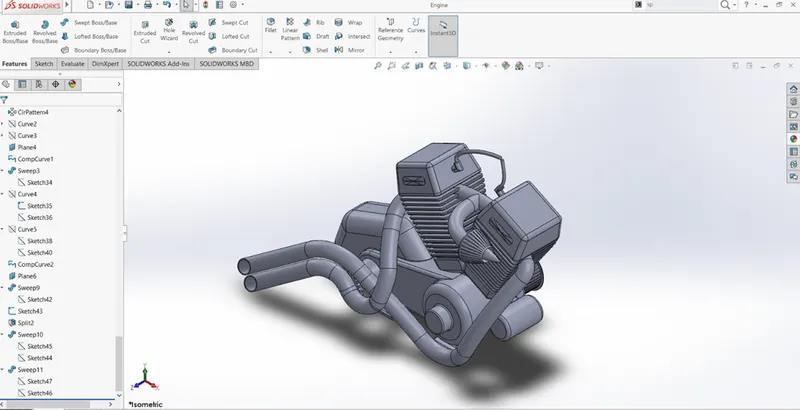
- ENGINE:
The engine is the main part and power source of a vehicle . the features used for modelling the engine are,
- Extrude
- Revolve
- Dome
- Fillet
- Chamfer
- Pattern
- Mirror
- Spilt
- Combine
- Sweep
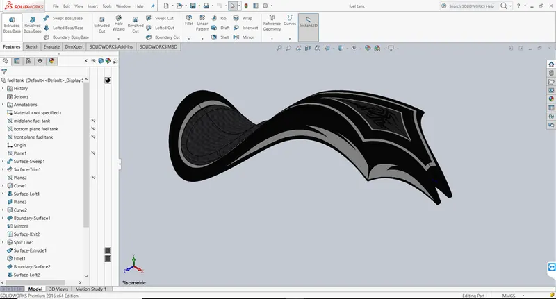
13.GAS TANK:
The gas tank holds the fuel and form important point of contact between bike and rider. The features used for modelling the gas tank are,
- Surface sweep
- Surface trim
- Projected curve
- Surface loft
- Spilt line
- Mirror
- Surface knit
- Fillet
- Shell
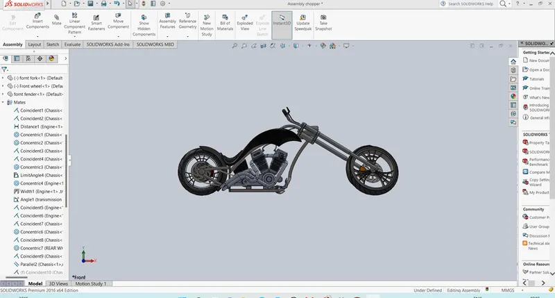
ASSEMBLY OF COMPONENTS/ PARTS:
In order to assembly the parts, all the parts are inserted in the assembly file one by one as per the requirements and give the required mates for the individual parts.
RENDER IMAGES:
Conclusion:
Here I used SOILDWORKS features and commands to complete design, modelling and assembly of AMERICAN CHOPPER BIKE, and develop a photo realistic rending image was done.