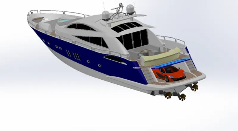
Radar Mast & Final Assembly of Yacht
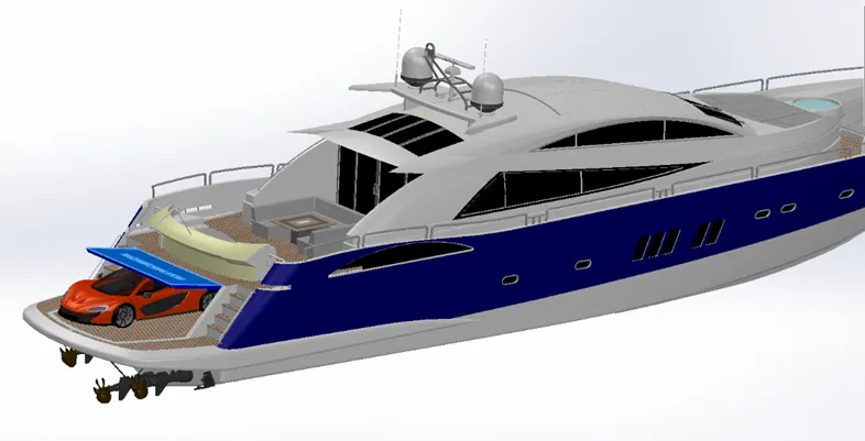
SUNSEEKER PREDATOR YACHT
OBJECTIVE:
The main aim of this project is to create a surface model of different yacht parts.
To assemble the parts modeled using the Solid works2021 software.
To create a photorealistic model of the yacht and render the model using the Solid works Visualization software.
The following are the key parts/models we will deal with in surface modeling using SOLIDWORKS.
Blueprint set-up
Modeling of propellers, radar
Modeling of the hull, garage door
Modeling of rear seats, middle seats, and front seats
Creation of the superstructure
Final assembly model of the Predator Yacht.
FEATURES USED IN MODELING THE YACHT:
Lofted surfaces are the surfaces generated by multiple 3D curves or existing edges creating a smooth tangency between the selected curves.
- SWEPT SURFACES:
Swept surfaces are the surfaces that are generated from a section curve positioned along a path.
- FILLED SURFACE:
The Filled Surface feature constructs a surface patch with any number of sides, within a boundary defined by existing model edges, sketches, or curves, including composite curves.
- SURFACE TRIM:
Surface Trim primarily used to cut away material from a surface and provides two modes: standard and mutual.
- EXTEND SURFACE:
Extend Surface is used to extend the surface which is already created. There are different options available on the extended surface. We can extend the surface as the same surface or we can extend the surface tangent to the surface.
- SURFACE KNIT:
Surface Knit is used to knit the two free edges/open edges of the surfaces together. Also, it reduces the gap between the two edges of the surface.
- SKETCH:
The sketch is the two-dimensional representation of the model concerning the plane/view from the outside of the model.
- REVOLVE:
To create a revolve feature: create a sketch that contains one or more profiles and a centreline, line, or edge to use as the axis around which the feature revolves.
- CIRCULAR PATTERN:
Circular Pattern is used to create a pattern of the propeller. By using these multiple patterns are created.
- EXTRUDE CUT:
Extrude Cut is another cool feature that helps to remove materials from the 3D model.
- MIRROR:
By using mirror faces with a mid-plane selected only the chosen faces within the revolve will be mirrored.
- Convert Entities:
Convert Entities enables you to copy model edges into your active sketch. These sketch elements are automatically fully defined and constrained with an On Edge relation. Convert Entities is like Offset Entities except that the offset distance is always zero.
- Offset Entities:
Copy a sketch entity to a specified distance from the original entity. Must have a sketch entity already drawn and selected to use this tool.
- Lofted Surfaces:
Creates a lofted surface between two or more profiles or sketches. Specify start and end constraints and add guide curves to control the path shape.
- Boundary Surfaces:
The boundary surface feature lets us to create surfaces that can be tangent or curvature continuous in both directions (all sides of the surface). In most cases, this delivers a higher quality result than the loft tool.
- Extruded Surfaces
Extrudes a sketch or selected sketch contours in one or two directions two create a surface features
- Revolved Surfaces
Revolves a sketch or selected sketch contours around an axis to create a surface features.
- Ruled Surfaces
Inserts ruled surfaces in a specified direction from edges. Tangent to surface, Normal to surface, tapered to vector, perpendicular to vector or sweep can be selected. We can also trim and knit the surfaces and remove any connecting surfaces.
- Projected curve:
A projected curve is typically used either in sweeps and lofts as path or guide curve. There are two types of projected curves:
- Sketch on Sketch:
Use two sketches to make a single curve.
- Sketch on surface:
Use a sketch to project on a surface.
- Split line:
The Split Line tool projects an entity (sketch, solid, surface, face, plane, or surface spline) to surfaces or curved or planar faces. It divides a selected face into multiple separate faces. We can split curves on multiple bodies with one command.
- Split point:
We can split a sketch entity to create two sketch entities. Conversely, we can delete a split point to combine two sketch entities into a single sketch entity.
- Fillet:
A fillet is an internal rounding of a corner or edge in a sketch or an edge on a surface.
MAJOR PARTS OF THE YACHT:
- Propeller
- Radar
- Hull
- Garage door
- Front seat
- Middle seat
- Rear seat
- Superstructure
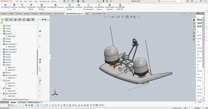
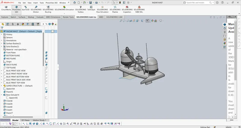
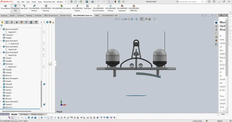
- Radar mast
PARTS DESCRIPTION:
- Propeller:
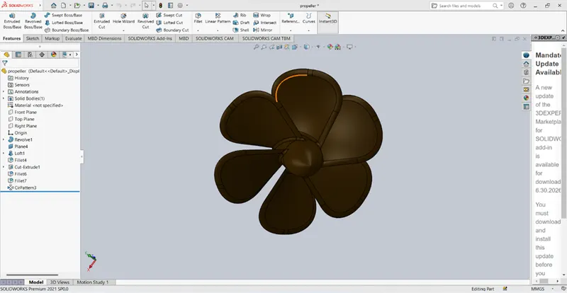
A propeller is a fan mechanism that transmits power by converting rotational motion into thrust. Usually consisting of 3 or more blades.
Features used to create propeller:
- Sketch
- Revolve
- Cut extrude
- Loft
- Fillet
- Circular pattern
- Radar:
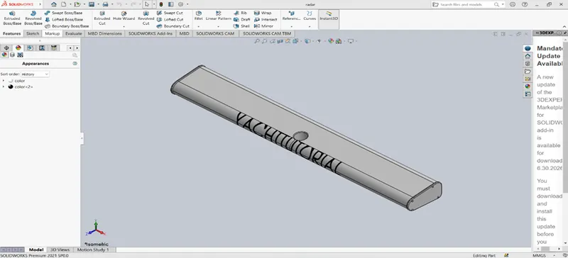
Marine radar is an X-band or S-band radar on the ship used to detect other ships and land obstacles.
Features used to create radar:
- Sketch
- Extrude
- Mirror
- Cut extrude
- Fillet
- Sketch driven pattern
Hull:
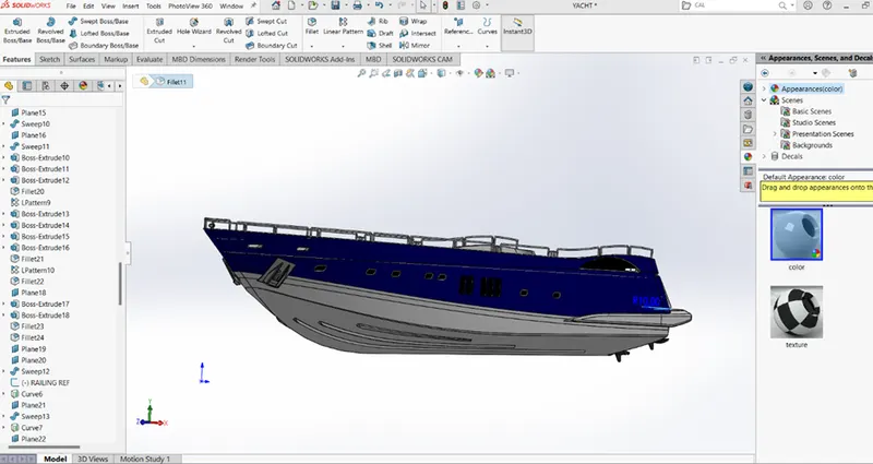
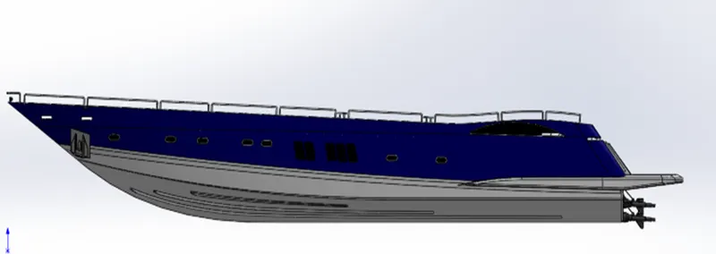
A hull is the watertight body of a ship or boat. The hull may open at the top of it may be fully or partially covered with a deck.
Features used to create hull:
- Sketch
- Project curve
- Swept curve
- Loft surface
- Extrude surface
- Extend surface
- Surface knit
- Extrude
- Mirror
- Cut extrude
- Fillet
- Pattern
- Split
- shell
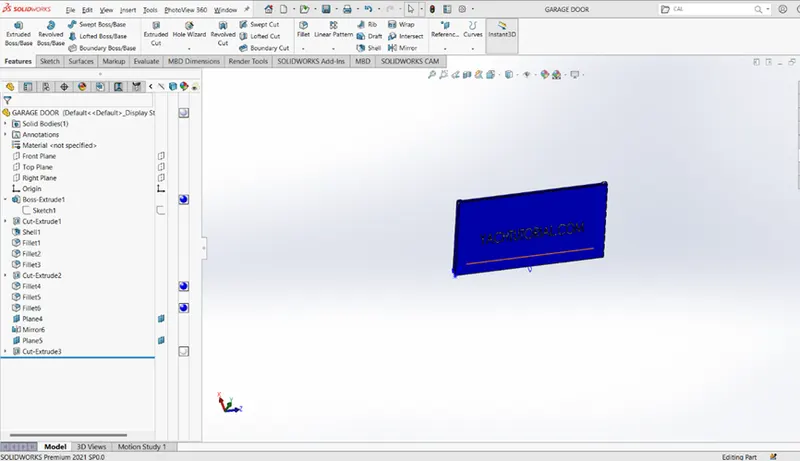
- Garage door:
The garage door is used to close the garage part in the hull.
Features used to create a garage door:
- Shell
- Chamfer
- Fillet
- Extrude cut
- Text
- Mirror
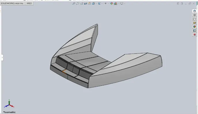
- Front seat:
The front seat is placed on the front part of the hull.
Features used to create front seat:
- Surface sweep
- Surface extend
- Surface trim
- Surface fill
- Surface loft
- Surface knit
- Chamfer
- Fillet
- Revolve
- Cut extrude
- Dome
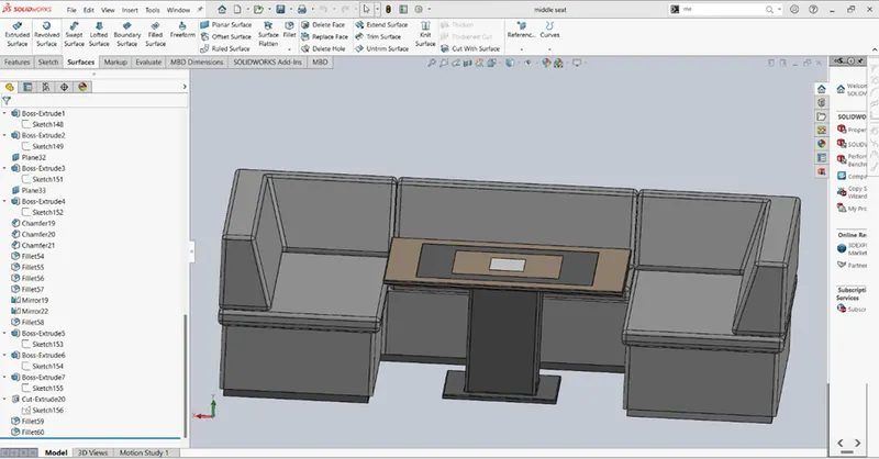
- Middle seat:
The middle seat is placed under the superstructure.
Features used to create middle seat:
- Boss extrude
- Cut extrude
- Fillet
- Chamfer
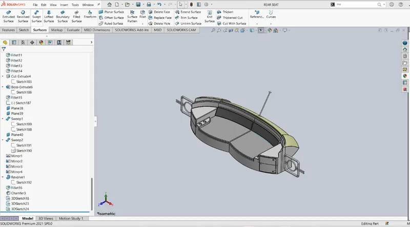
- Rear seat:
The rear seat is placed at the back of the hull.
Features used to create rear seat:
- Fillet
- Chamfer
- Split line
- Cut extrude
- Extrude
- Surface offset
- Surface trim
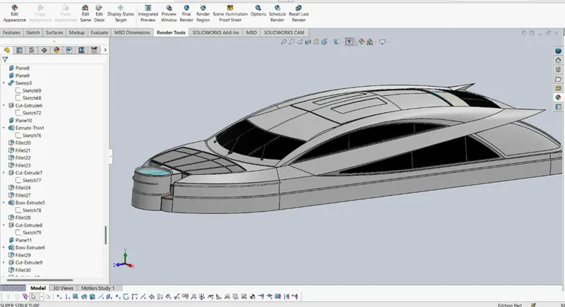
- Superstructure:
In this yacht, it is the name given to the ship that emerges from the deck.
Features used to create superstructure:
- Sketch
- Project curve
- Surface trim
- Surface fill
- Extend surface
- Surface extrude
- Lofted surface
- Boundary surface
- Delete surface
- Fillet
- Swept surface
- Surface knit
- Boss extrude
- Cut extrude
- Split
- Mirror
- Radar mast:
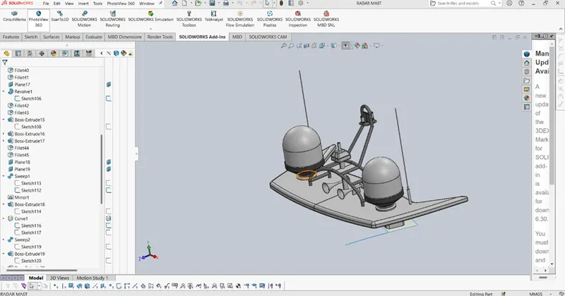
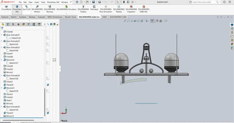
Radar mast is placed on surface of the super structure.
Features used to create radar mast:
- Revolve
- Sketch
- Boss extrude
- Fillet
- Mirror
- Swept boss/base
- Shell
- ASSEMBLY:
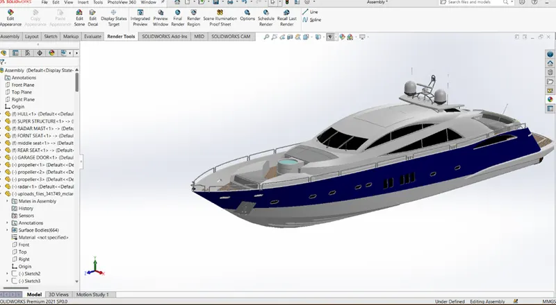
The modeled parts of the yacht are inserted in this assembly environment.
The possible mate conditions are given to assemble the yacht. An assembly is a document in which parts, features, and other assemblies (sub-assemblies) are mated together. The parts and subassemblies exist in documents separate from the assembly. For example, in an assembly, a piston can be mated to other parts, such as a connecting rod or cylinder. This new assembly can then be used as a sub-assembly in an assembly of an engine. The extension for a SolidWorks assembly file name is SLDASM.

- RENDERING:
The photorealistic rendering of the assembled model is created.
The process of a digital image is created.
CONCLUSION:
Thus the project Design, Assembly and Photo-Realistic Rendering of an American Predator Yacht was Modelled and Rendered successfully.