Week 9 - Project 1 - Door Trim Lower with Engineering Features
INPUT :-
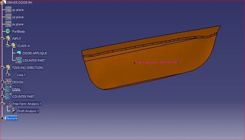
Class-A surface from a vehicle door is provided to me to design a part model and validate it.
From this Door Applique as a Class - 'A' surface, first I need to check whether the surface has some boundary irregularities and any open boundaries.
- After checking I need to create a Tooling Axis for the Class - 'A' surface. And also if I need to create the side core tooling axis for the surface.
- Then I need to create the Class - 'B' and Class- 'C' surface with the help of the Class - 'A' surface.
Design :-
Tooling axis creation :-
The tooling axis is the direction of drawing a sheet metal where the finished component is easily ejected on a particular direction and axis. The tooling axis is important for removing the material when finished.
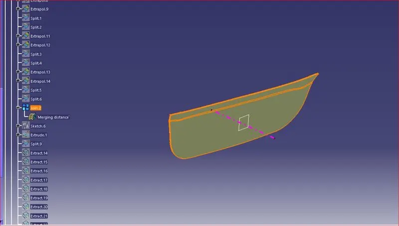
- Create An Axis system, from that axis system I will get two cross-sections, by using that cross-section lines I will create the tooling axis for the surface.
- Or, if it is a flat surface I will create a point using surface and create a line using the Axis system.
Draft Analysis :-
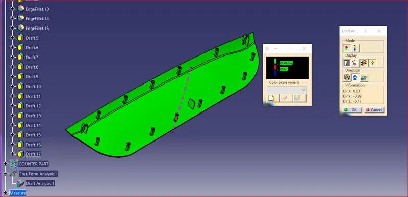
Now perform draft analysis to check whether tooling axis has negative draft.
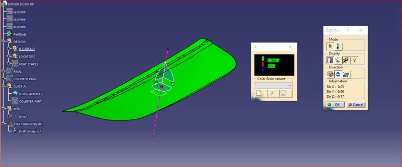
There is no negative draft on class-A surface.
B-SURFACE CREATION :-
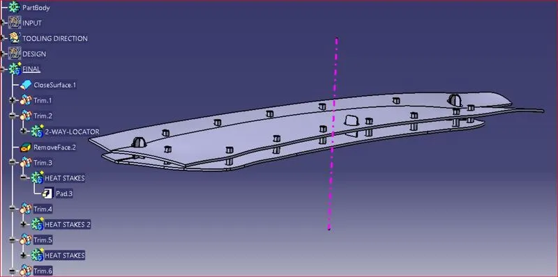
- First extract surface from the class - A surface without the fillets and then trimming and extrapolating them to join them, and after that offset the surface to 2.5 mm thickness which forms as the Class - B surface.
- Then create class-b surface with fillet.
- After that create the boundry from class-a surface, then surface c will be created.
- Then trimming and joining all the surface together c-surface will be created.
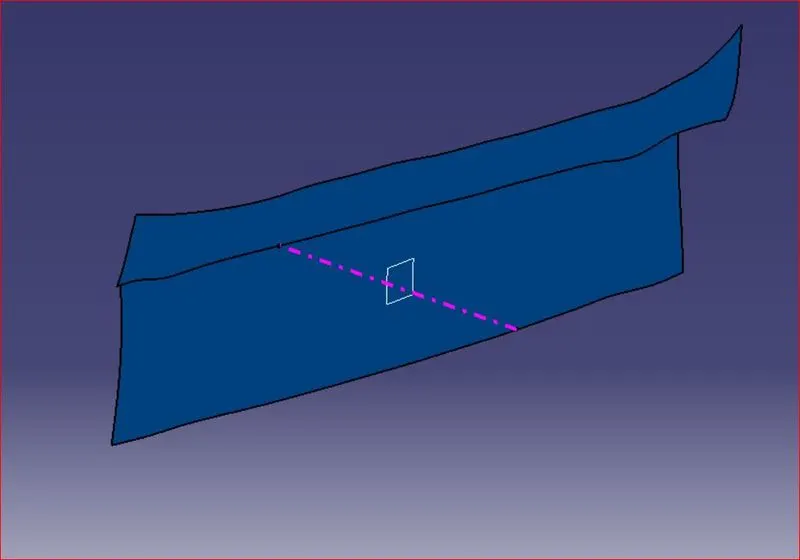
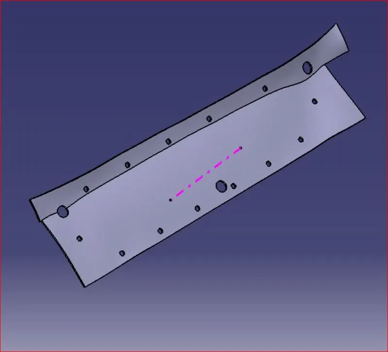
Final Result
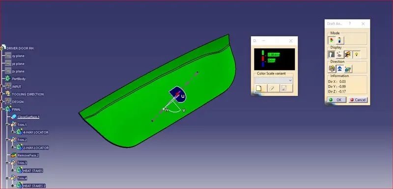
Draft Analysis :-
When a plastic component is made, we can observe a draft angle given on each side from the base that is lesser than 90 degrees. This is because in the criteria of making a plastic material the mold should release the material when finished. if the mold surfaces are 90 degrees the material won't release from the mold because of friction due to contraction of material when cooled.
To resolve this problem we CAD engineers maintain a standard rule to design the plastic mold or die's in such a way that there is no problem while ejecting the plastic component. So a minimum of 3 - 10 degrees of draft angle is given to every plastic component while designing.
Design of Locators :-
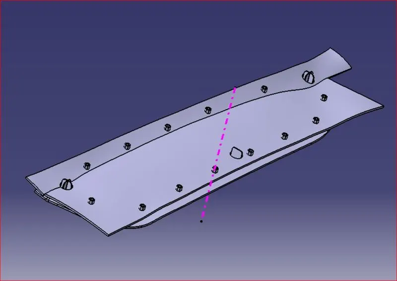
Locators work as a 3-2-1 principle which is basically to fix a component to be machined or to be placed in an ideal position. There are a total of 12 degrees of freedom, 6 rotational and 6 translational. In this, I need to fix any 11 degrees of freedom permanently and anyone to be clamped or fixed temporarily. In this scenario, Locators come into place. there are 4-way locators, 3-way locators, and more.
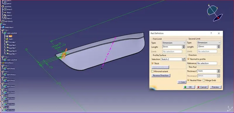
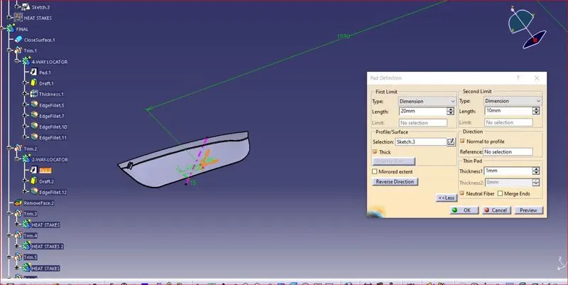
while making a locator the distance of all locators from the surface should be equal for all. The thickness for all should be around 1 mm. A minimum of 20 mm distance drafting is given to validate in draft analysis. And by placing these locators, we can arrest 11 degrees of freedom.
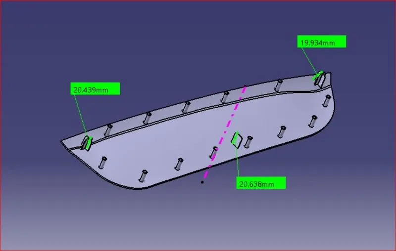
Heat staking :-
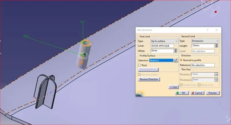
This is also a fixing method of a plastic component to another dissimilar or similar surface or metal part. But in this process, both of them are joined together by thermal welding and can not be removed after that. A Boss or a stud is made on the plastic part, which is then protruded onto the opposite part and reformed after the locators fix the part temporarily and then thermal welded on the boss.
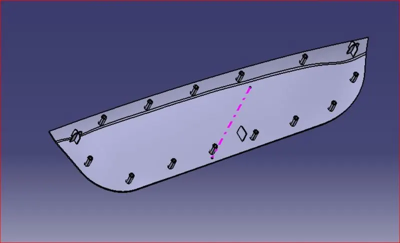
Draft Analysis of Locators :-
Fixing location on surface
Final Result:-