Week 9 - Project 1 - Door Trim Lower with Engineering Features
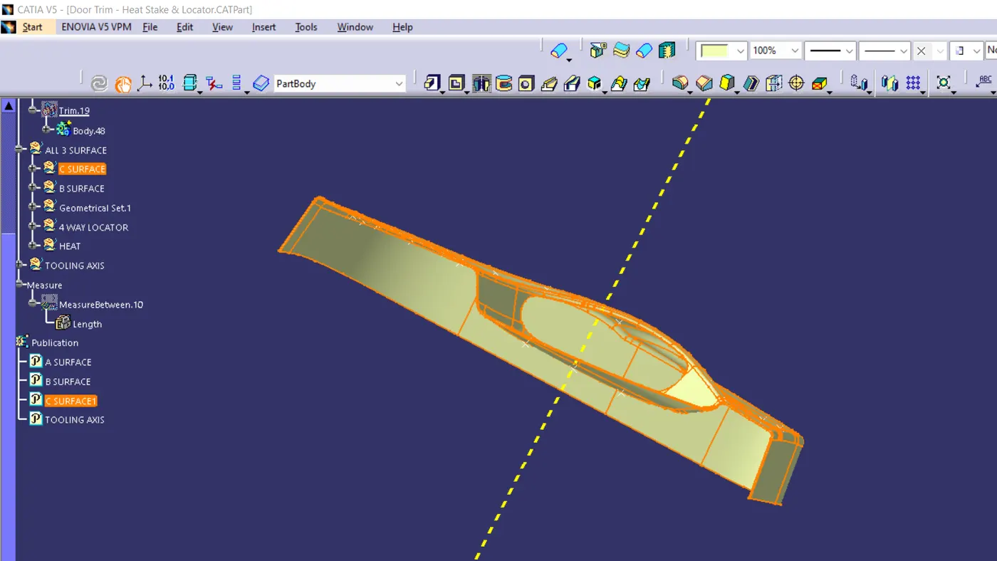
A AND B SURFACE TOGETHER
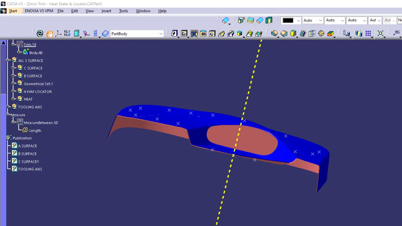
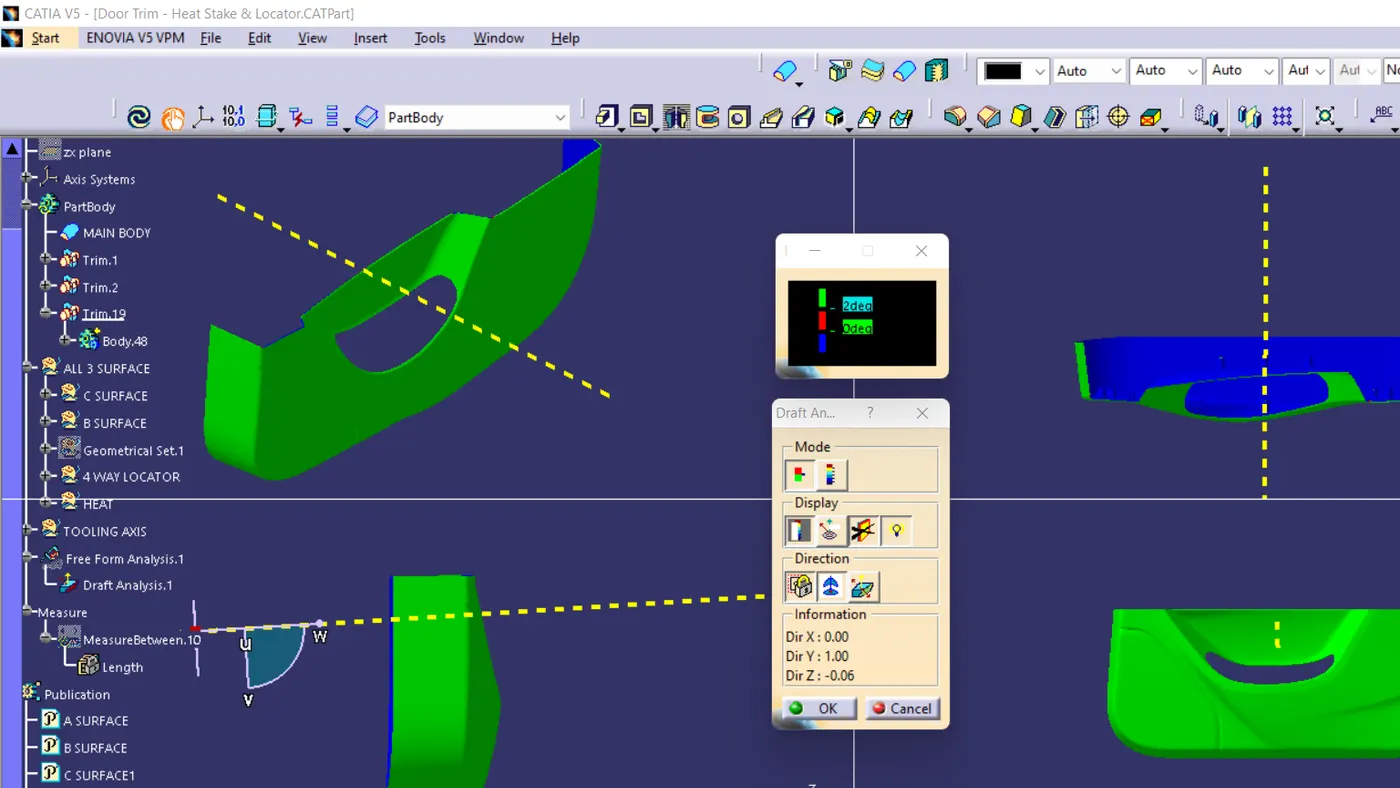
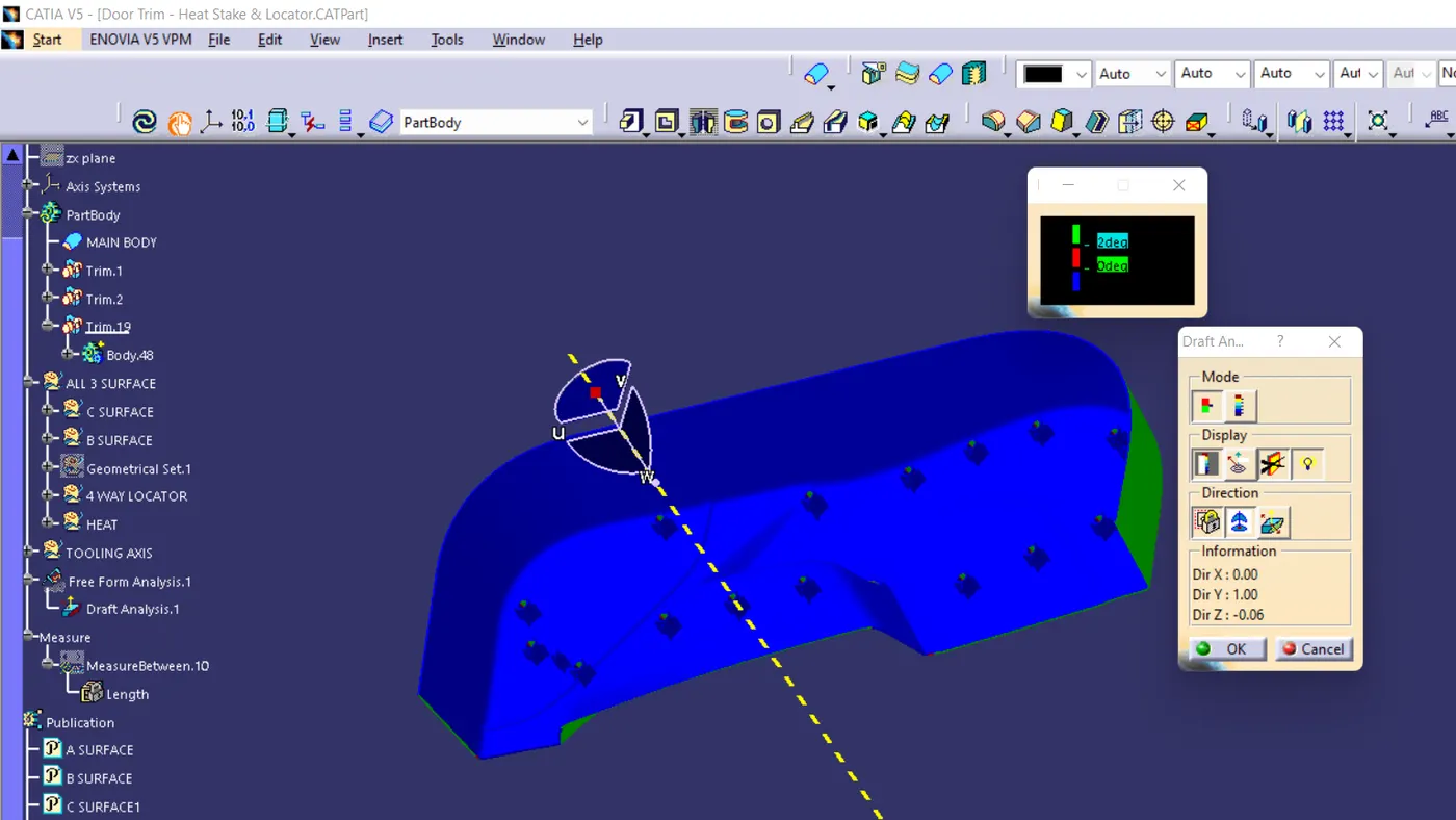
DRAFT ANALYSIS
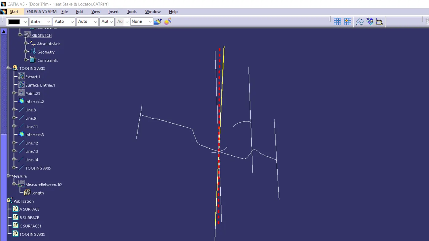
the A surface is intersected with the help of an axis which is made on the lowest surface of the A surface, in both directions like in the above picture . from this, we will get two tooling axis in both directions. through bisecting this two tooling axis we will get the main tooling axis which I marked with red color.
by using this tooling axis, we going to make the draft in our part. for every draft, we put this tooling axis as the propagating direction.
first, we take the A surface for the draft analysis. .then at last after completing the whole part we use the same tooling axis for the draft analysis.
from the final product I got 2 analyses, one was green and the other was blue, there is no other color appeared which means that the draft was equal in all directions, so the tooling axis is successful
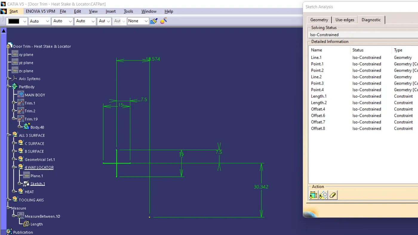
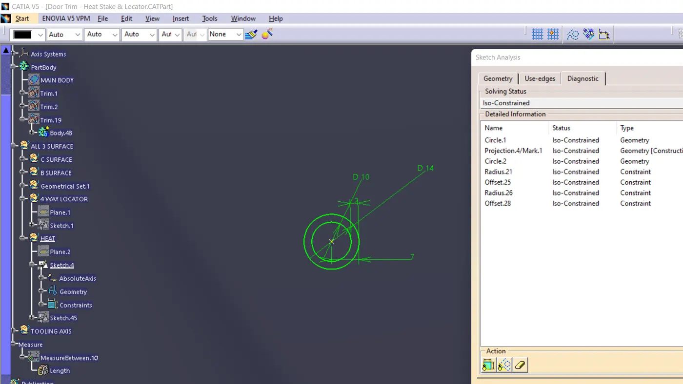
the locators and Heat stakes are placed in exact point which is mentioned on sample figure. and both locators and Heat stakes are drafted with the direction of the tooling axis. now the draft for the locators and heat stakes got the same
i increased the length of the locators usual than normal measurements because the rules for the locators and heat stakes told
in the lecture was " always the length of the locators should be higher than the heat stakes"
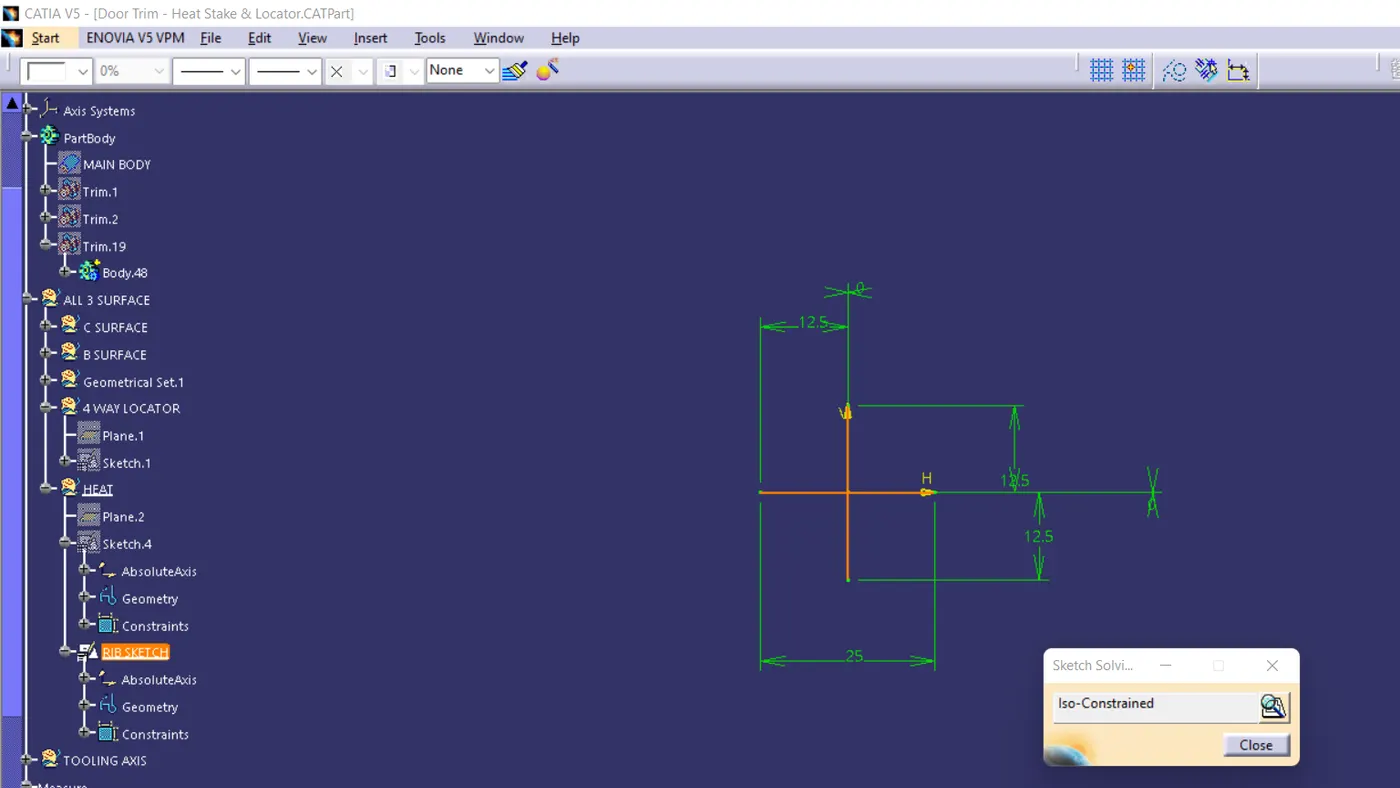
also, I gave ribs for the heat stakes. like in the sample figure. the finished part successfully compiled the draft analysis