Week 8 - Challenge 4 - Bumper
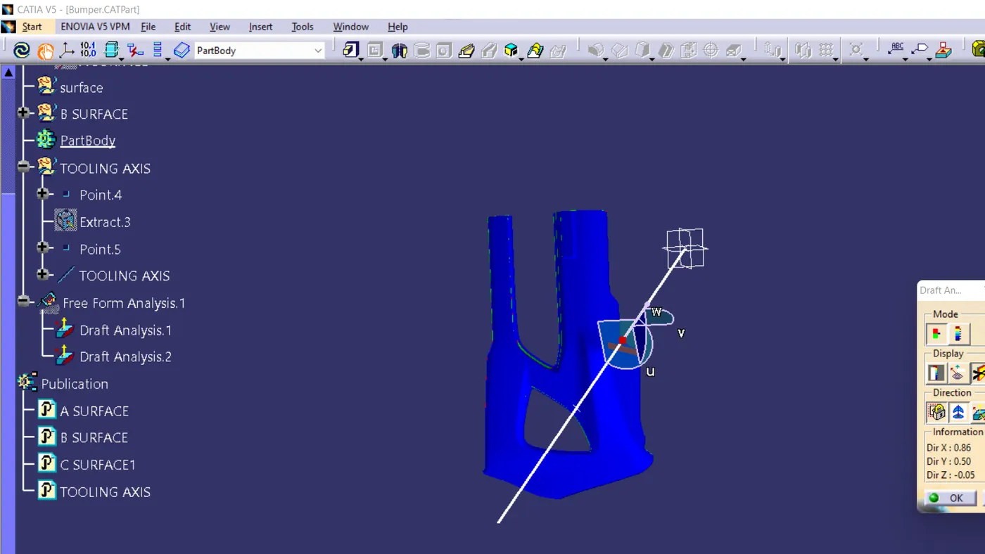
TOOLING AXIS
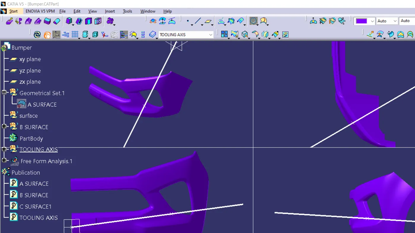
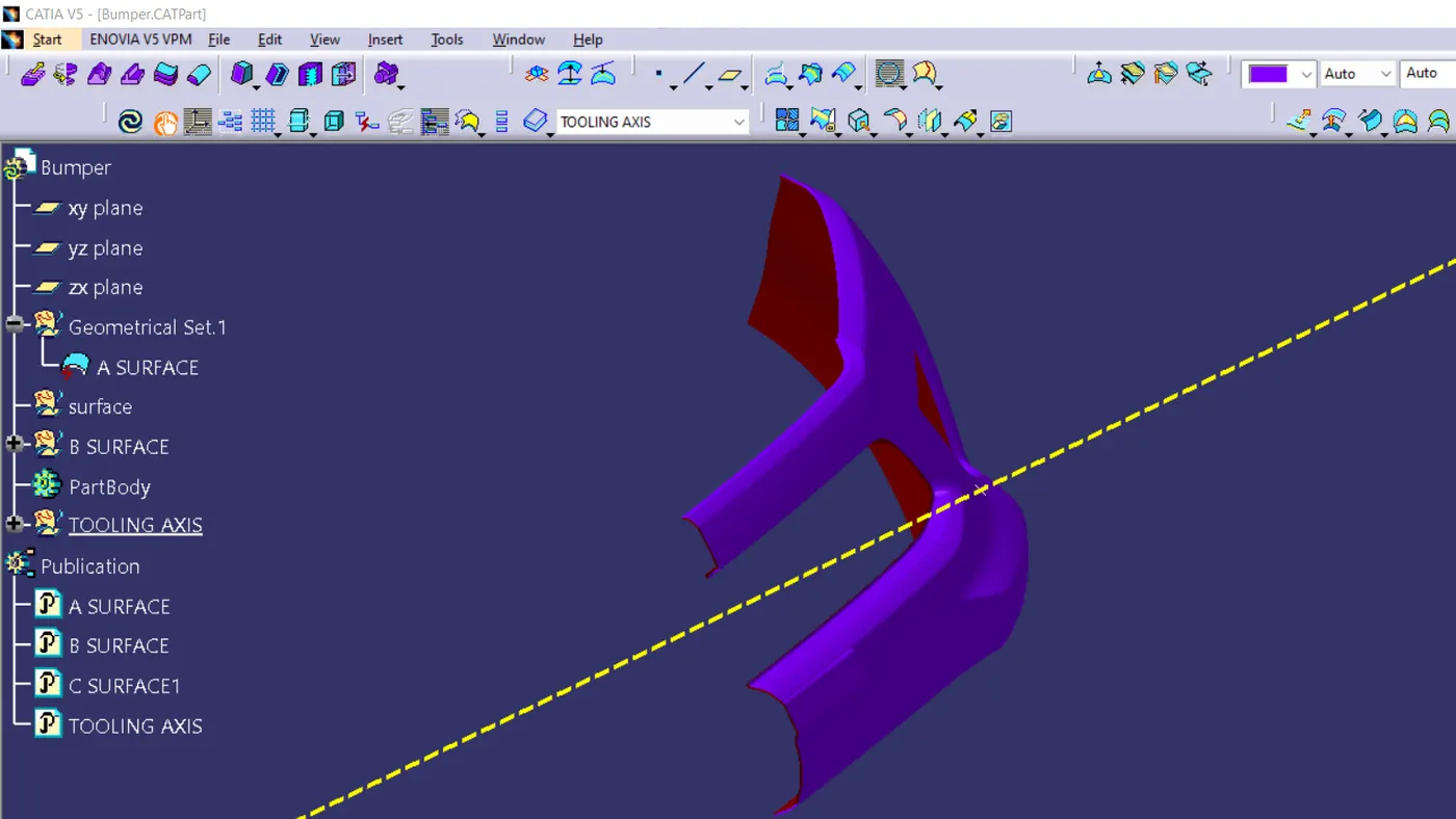
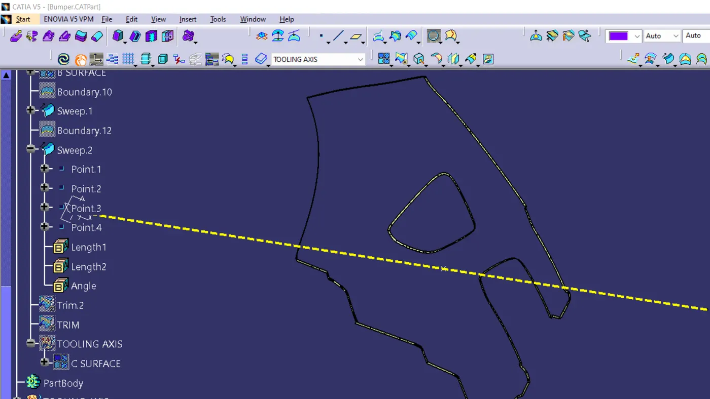
First, ensure that the Class-A surface is properly joined and has no discontinuity. Select the boundary command from the toolbars and then select the Class-A surface. A boundary should only appear on the outer edges of the component.Generally, the tooling axis is created using bisecting lines method. But in this model, we observe that the side walls are not given any draft. Hence, just extracted a surface which is good to see all the remaining surface from that surface and created a point on that extracted surface then made a point on the center and with these 2 point created the tooling axis
drafting analysis
change the martial mode to the material- take the draft analysis-
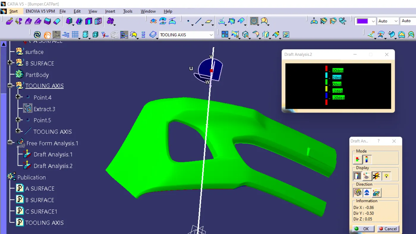
draft analysis is made by the analysis tool,after the part is created the martial shading is changed to material by using the customize using parameter - choose the material option -after that come back to the feature draft analysis - here select
the compass to change the direction of tooling. -after clicking the compass icon align with the tooling axis - locking it using a nearby option called lock . by now a red cross will appear at the mouse pointer and the color of the part will turn green. blue or red or green shows the draft is good and attained good value .red shows the neutral .blue shows negative