Week 9 - Project 1 - Door Trim Lower with Engineering Features
Week 9 - Project 1 - Door Trim Lower with Engineering Features
OBJECTIVES:
- To create the class B and class C surfaces from the given class A surface
- To form a solid geometry by combining all the surfaces
- To create engineering features for the solid part whilst following the design rules
- To perform draft analysis on the class A surface and the solid part model
PRE-DESIGN CHECKS:
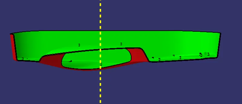
Before starting the creation of the class B surface we must ensure that the given class A surface is properly closed and the surface continuity is proper. This can be done either with the help of the join operation or by using the boundary feature.
TOOLING AXIS:
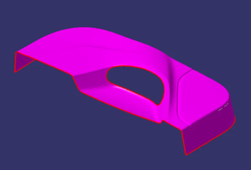
- The next step is to create the tooling axis for the part which will determine the direction in which the core and cavity of the mould will move.
- Designer must ensure that all holes and slots are covered in the main tooling and thus side core must be avoided whenever possible
- After analysing visually for the best possible tooling axis, an axis system is created on the centre of one of the surfaces of the door trim.
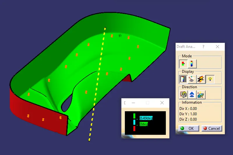
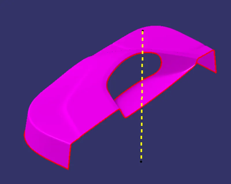
- The main tooling axis is created normal to the y direction
DRAFT ANALYSIS:
- Draft analysis is done on the class a surface after the tooling axis has been obtained
- The part must have a minimum draft angle of 0.5 degrees on all the tapered faces
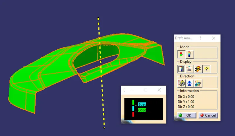
- Using the feature draft analysis tool and the compass the part surface is validated for the minimum draft criteria
CLASS B SURFACE
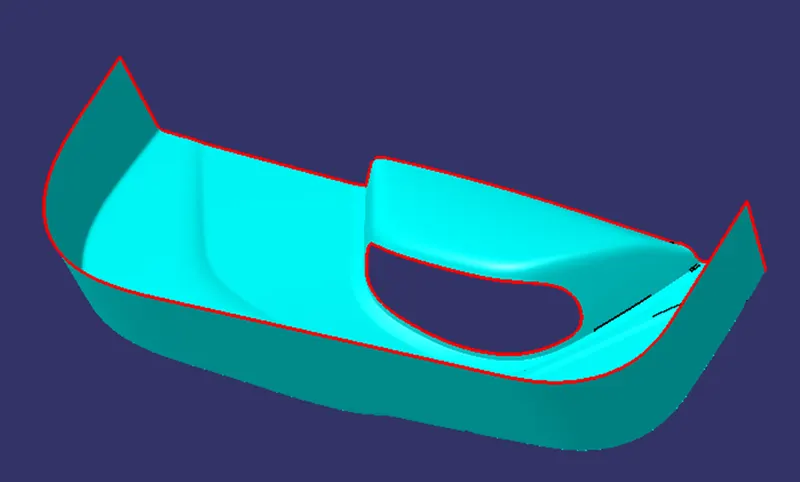
- After all the validation has been done, the class B surface is created by offsetting the class B surface to a distance of 2.5 mm
- After offsetting many openings in the surfaces are found which are closed with the help of sweep, multi sections-surface and fill command.
- The class B surface is then extrapolated to trim it along with the class C surface
CLASS C SURFACE
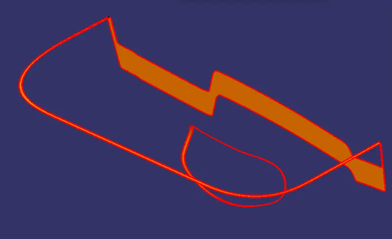
- The class C surface which connects the class A and class B surface is created by sweeping the boundary of the class A and using the class A as a reference.
- The sweep is divided into several parts in order to avoid complexity
- Surfaces which are parallel to the tooling direction are swept with the tooling axis as reference and with a draft angle of 3 degrees
PART:
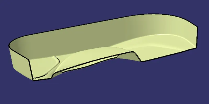
The final trim is created by joining the Class A and C surface and finally trimming it with the Class B surface. The combination of class A, B and C surface is then converted into a solid with the aid of close surface command in the part workbench
DESIGN OF LOCATORS:
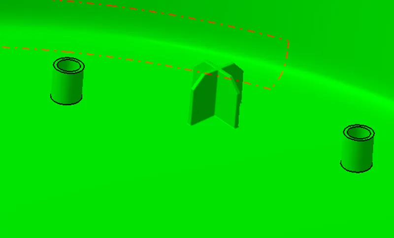
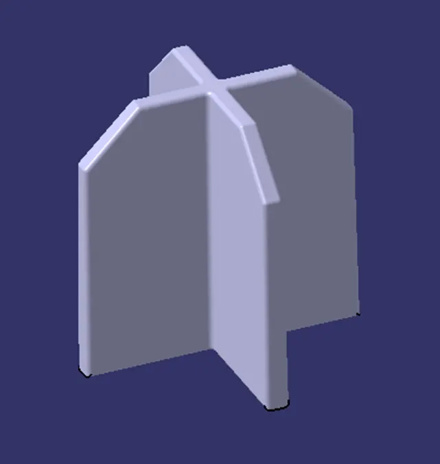
- The main purpose of locators is to facilitate proper locking of two components together while assembling and to arrest the maximum degrees of freedom possible.
- These locators are similar to guide pins provided in mould.
- The two types of locators used are two way locator and four way locator.
- We have positioned two 4 way locators in our model which meet the rib design criteria.
DESIGN OF HEAT SKATES:
- Heat stakes are used in thermoplastics to assemble two parts together by locally heating and cooling the plastic material and allowing it to reform itself and act as a joint for the two materials.
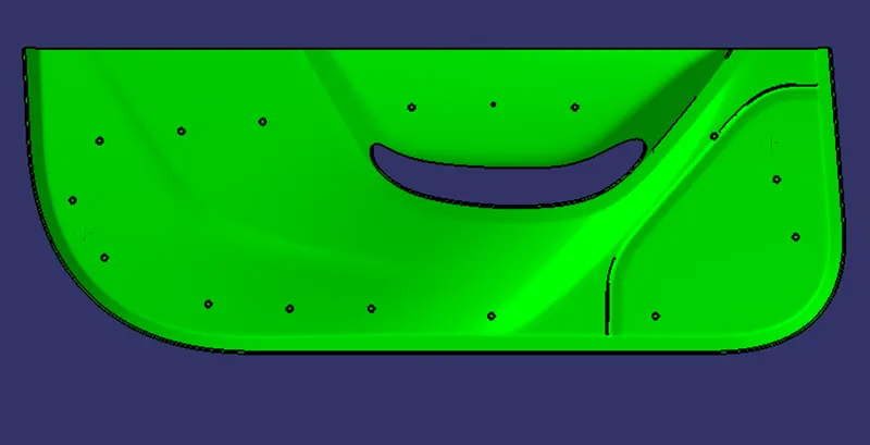
- We have placed 15 heat stakes in the model based on the reference points provided as the input.
- One of the important factor to be considered while designing the heat skates is the height of the heat skates. It should always be less than the height of the locators
DRAFT ANALYSIS ON PART:
- Draft analysis is done on the final part with the tooling axis as reference
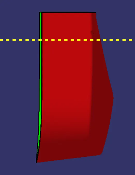
- Green surface indicates the areas where the draft is more than 0.5 degrees.
- Red surface indicates the area having negative draft.