Week 8 - Challenge 2 - Switch Bezel Design
Week 8 - Challenge 1 – Switch bezel design
OBJECTIVES:
- To create the class B and class C surfaces from the given class A surface
- To form a solid geometry by combining all the surfaces
- To perform draft analysis on the class A surface and the solid part model
PRE-DESIGN CHECKS:
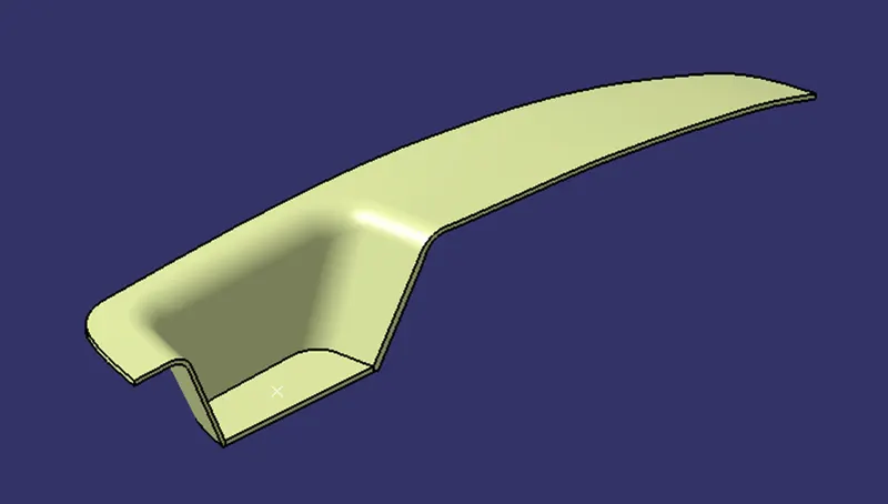
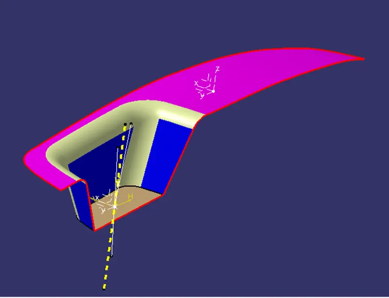
Before starting the creation of the class B surface we must ensure that the given class A surface is properly closed and the surface continuity is proper. This can be done either with the help of the join operation or by using the boundary feature.
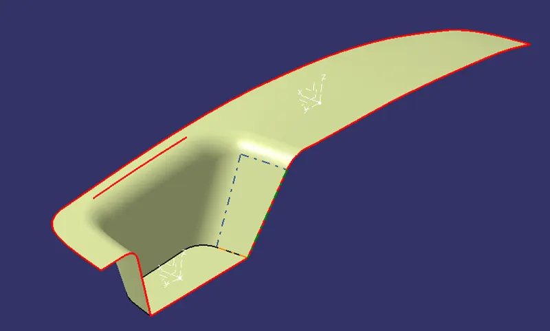
While creating a boundary on the Class A surface it can be observed from the above image that there is an opening on the surface which has to be closed. This opening is closed by joining all the surfaces and giving the merging distance as 0.003mm (max allowable limit)
TOOLING AXIS:
- The next step is to create the tooling axis for the part which will determine the direction in which the core and cavity of the mould will move.
- Designer must ensure that all holes and slots are covered in the main tooling and thus side core must be avoided whenever possible
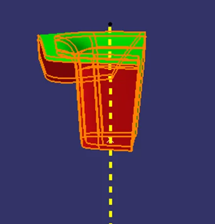
- After analysing visually for the best possible tooling axis, an axis system is created on the centre of the base surface of the switch bezel
- First the tooling axis is drawn along the YZ plane and then along the XZ plane
- Both these axis are the bisected in order to obtain the main tooling axis for the component
DRAFT ANALYSIS:
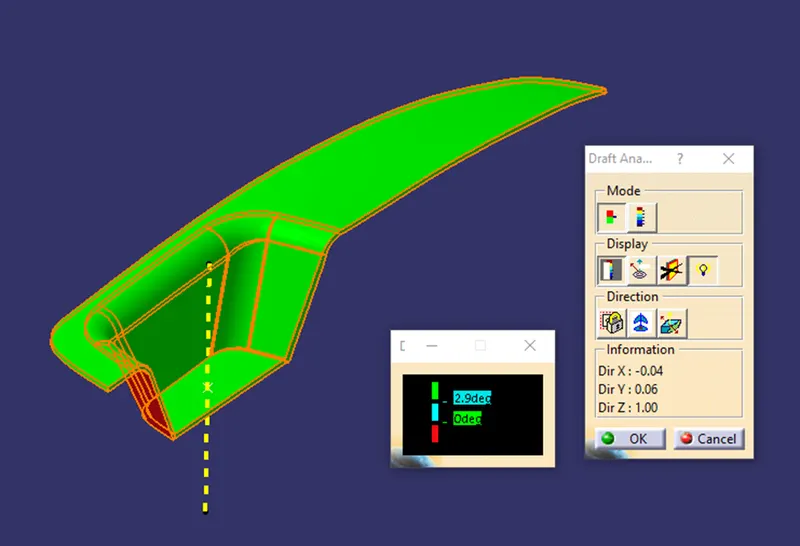
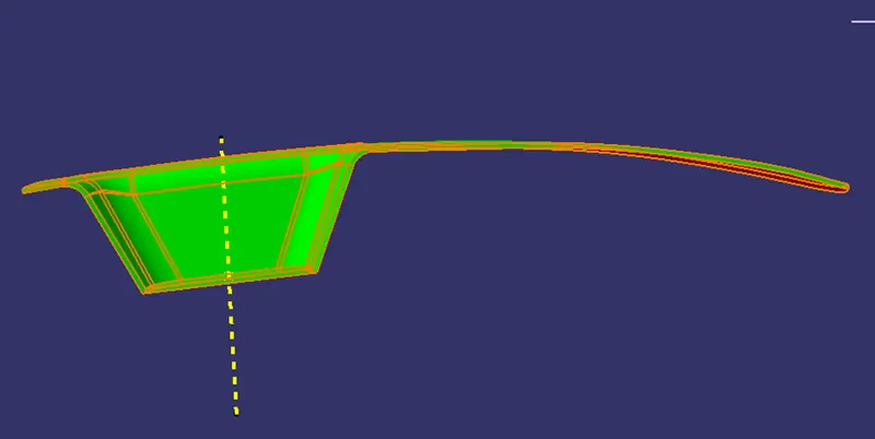
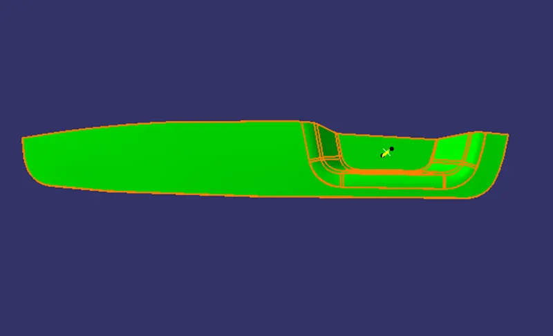
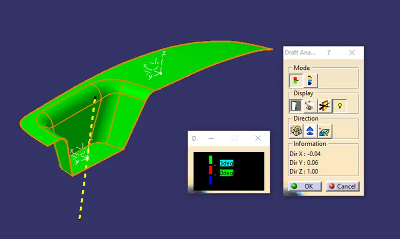
- Draft analysis is done on the class a surface after the tooling axis has been obtained
- The part must have a minimum draft angle of 3 degrees on all the tapered faces
- Using the feature draft analysis tool and the compass the part surface is validated for the minimum draft criteria
CLASS B SURFACE
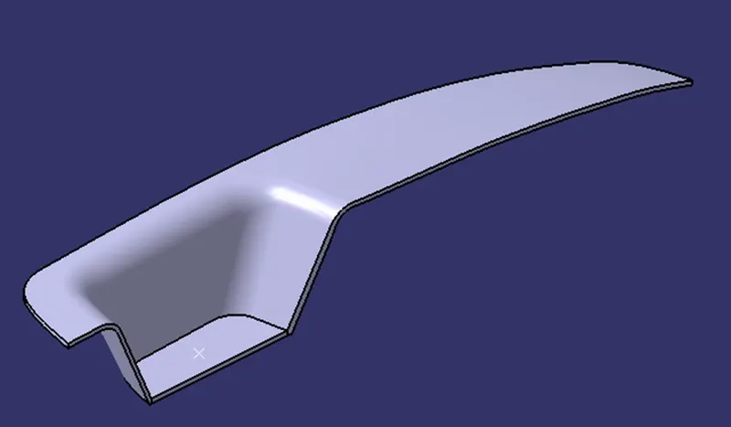
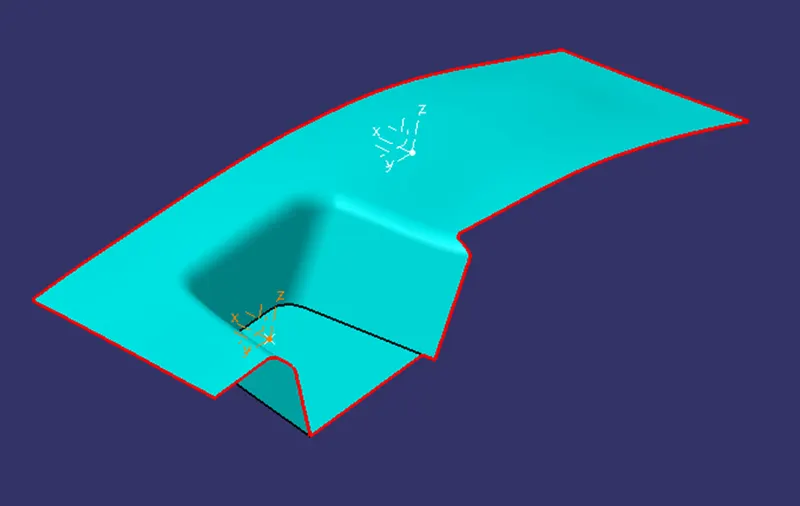
After all the validation has been done, the class B surface is created by untrimming and offsetting the class A surface at the required distance which is 2.5 mm
CLASS C SURFACE
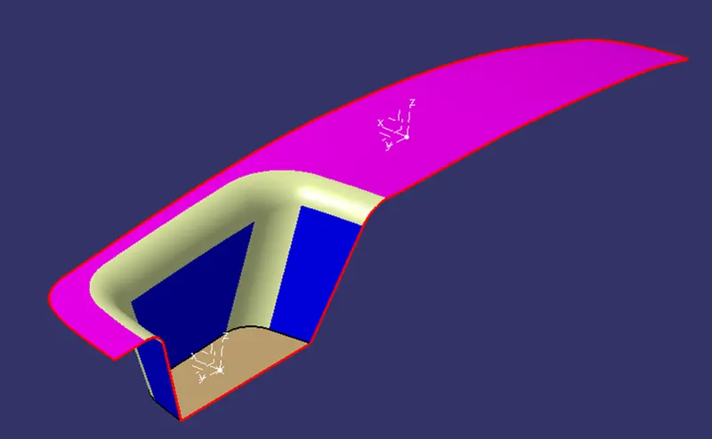
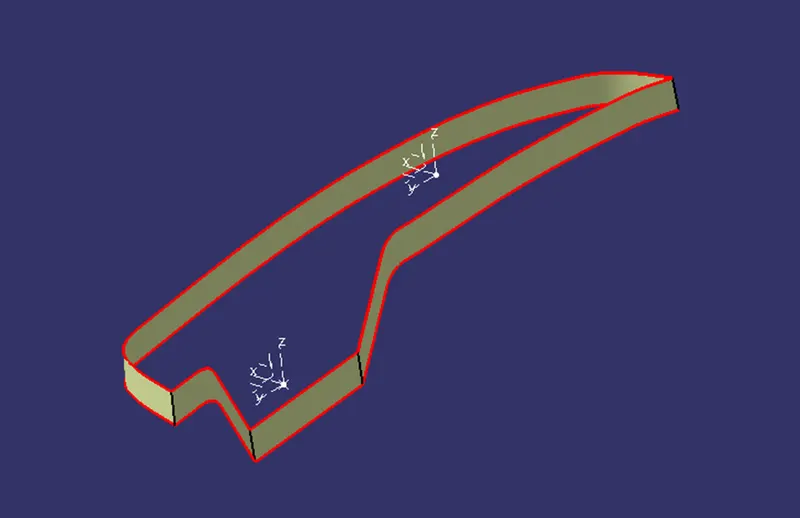
The class C surface which connects the class A and class B surface is created by sweeping the boundary of the class A surface along the tooling axis with a draft angle of 3 degrees. Since the geometry is a bit complex and contains sharp corners, the sweep is split into four parts and then all of them are finally trimmed to obtain the final class C surface
PART:
The step part of creating the final trim is to join class A and class C surface. While joining the class A and C surface an opening larger than 0.003mm was observed. Thus the class A and C surface had to be extrapolated and trimmed to get the required output. The combination of CLASS A, B AND C surface is then converted into a solid with the aid of close surface command in the part workbench