Radar Mast & Final Assembly of Yacht
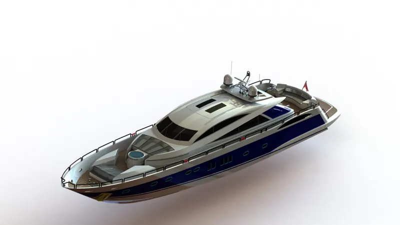
SUNSEEKER PREDATOR YACHT DESIGN AND RENDER
Objective:
- To design and assemble each and every component of the Yacht
- To acquire knowledge about part design and surface design
- To understand the flow of process in designing a yacht
- To render photo-realistic images of the yacht
Introduction
Sunseeker International is a British luxury performance motor yacht brand. Originally named Poole Power Boats, the company was founded by brothers Robert and John Braithwaite in 1969. The company changed its name to Sunseeker International in 1985 and has since become a global icon. The predator series is one of the most luxurious yacht and is the flagship series from the sunseeker brand. We intend to replicate the predator modle by the help of the blueprints provided and make a detailed 3d modle of the yacht
Design methodology
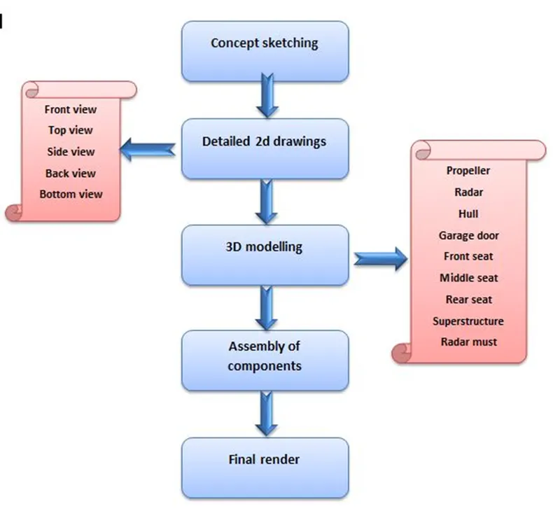
Features And Tools Used In The Design Process:
Solid modelling:
1) Boss Extrude
- Boss extrude is the most basic and important function in solidworks used to create a solid from a sketch
- It transforms the 2d sketch into a 3d object
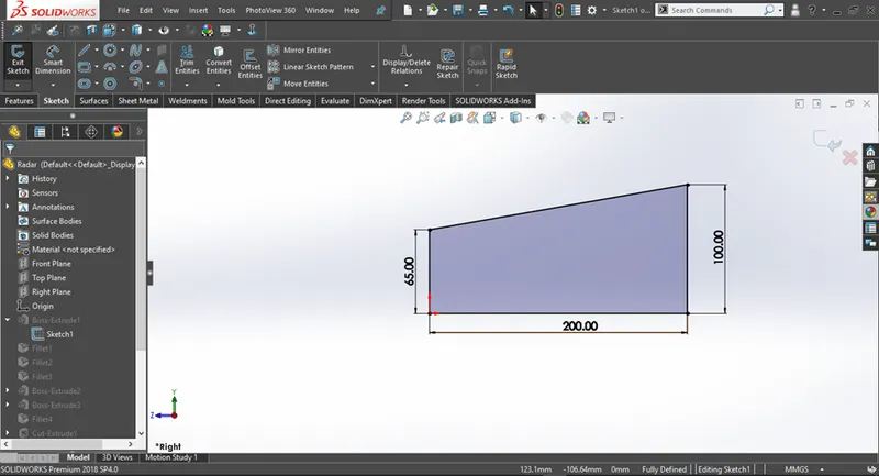
Figure 1.1 Fully defined 2d sketch
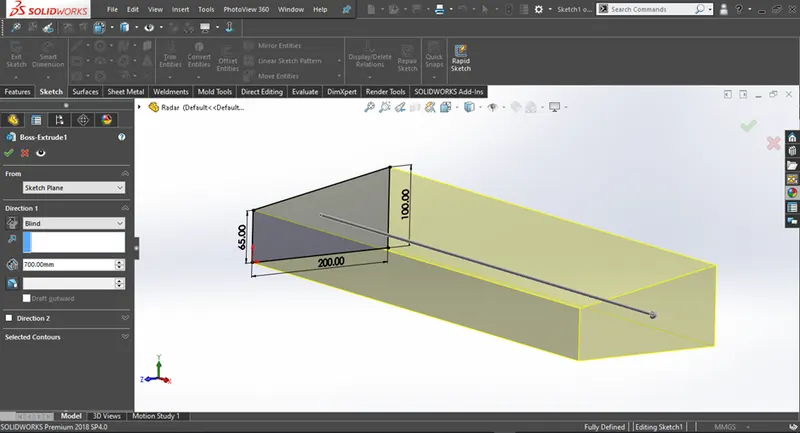
Figure 1.2 Boss Extrude feature been aplied
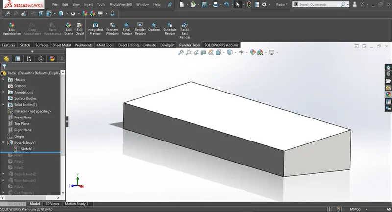
Figure 1.3 3d geomerty created from Boss Extrude
2) Cut Extrude
- Cut extrude is used to remove material from a solid or a surface
- It requires a sketch and a geometry which has to be cut
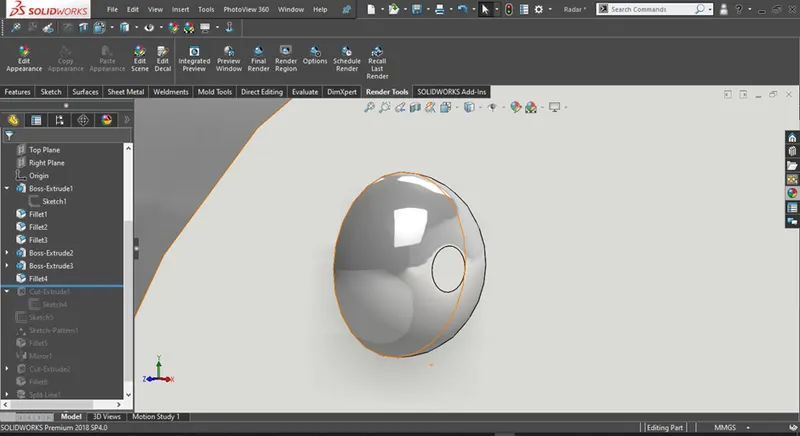
Figure 1.4 3d geomerty to be cut
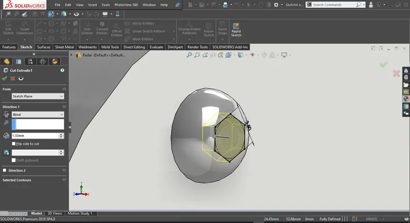
Figure 1.5 Cut Extrude feature been aplied
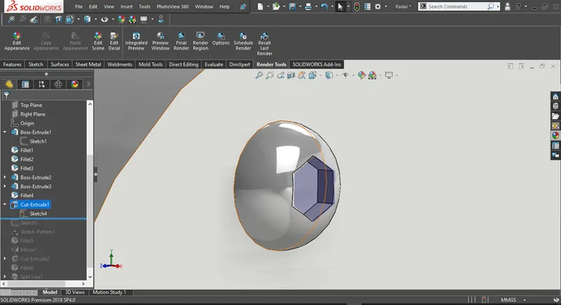
Figure 1.6 Resulting geometry from cut extrude
3) Revolve
- Revolve is used to create solid/surface by revolving a sketch around a given axis
- Based on the selection of axis the revolve shape will also change
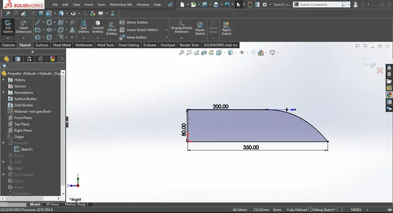
Figure 1.7 Fully defined 2d sketch
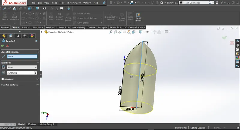
Figure 1.8 Revolve Boss/Base feature been applied
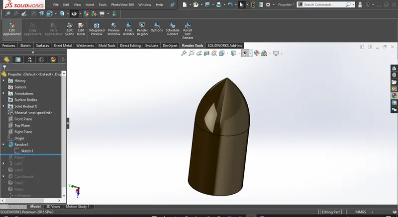
Figure 1.9 3d geomerty created from Revolve Boss/Base
4) Fillet
- Fillet feature is used to round off sharp edges od a 3d model and given it a more cleaner look
- The most commpnly used fillet options are constant size fillet and the full round fillet
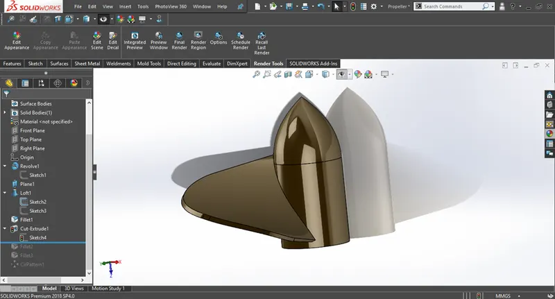
Figure 1.10 model before applying fillet
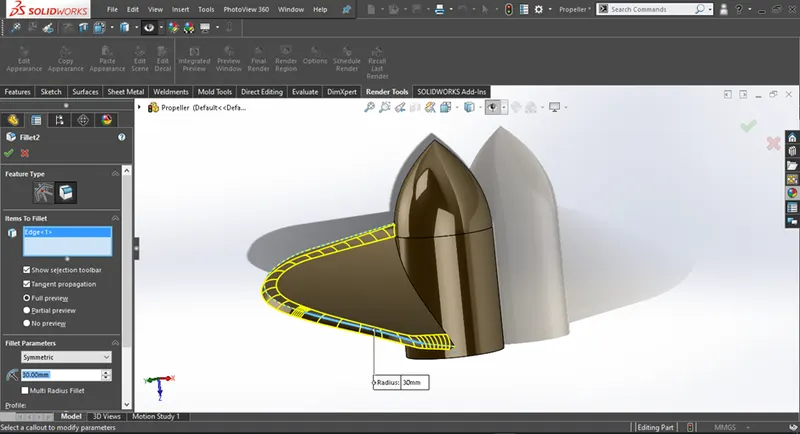
Figure 1.11 Applying fillet tto the model
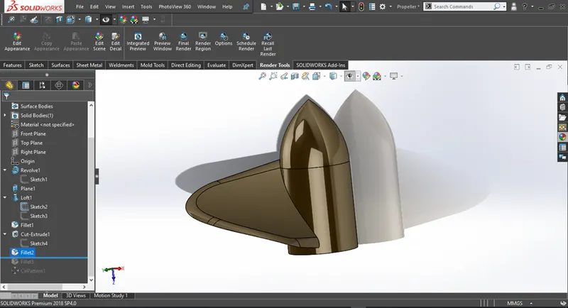
Figure 1.12 Resulting geomertry from fillet
5) Shell
- Shell command is used to make a 3d object hollow by reomving the inner geometry while maintainig a wall thickness as desired by the user
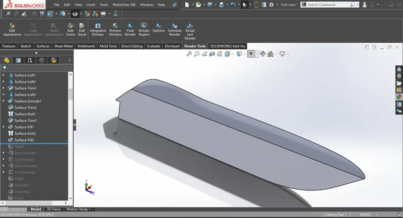
Figure 1.13 Before aplying shell feature
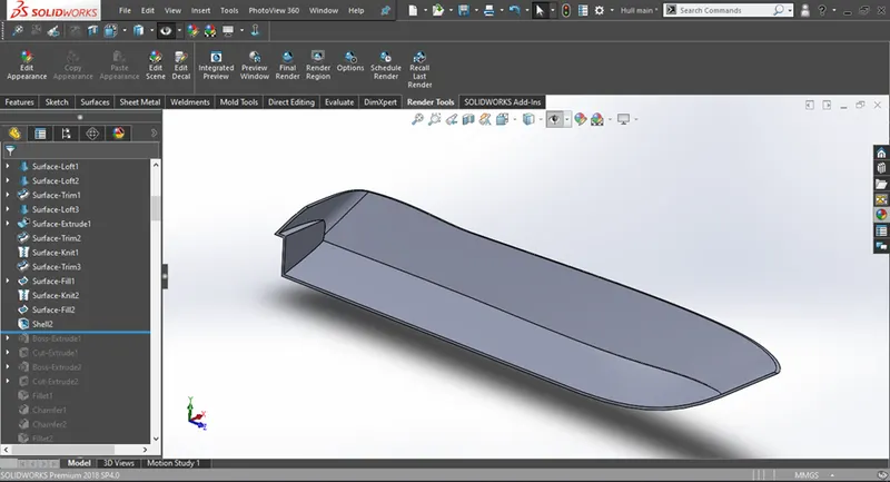
Figure 1.14 After aplying shell feature
6) Projected Curve
- Projected curves creates a 3d curve based on two 2d skethes provided by the user
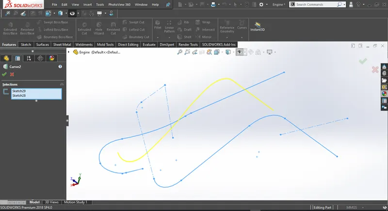
Figure 1.15 Example of projected curve
7) Mirror
- The mirror option helps duplicate a feature or a body based on a plane or a fcae slected by the user
- The user can create only half of the required geometry and the mirror it to get the required result
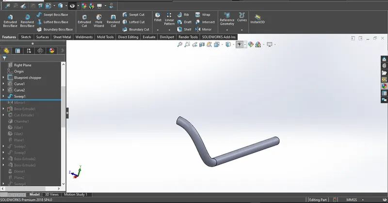
Figure 1.16 Before apllying mirror

Figure 1.17 After apllying mirror
Surface modelling:
1) Surface Extrude
- Surface extrude is used to create a 3d surface from a 2d sketch(both open and closed sketches)
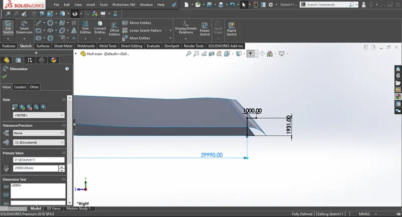
Figure 2.1 Fully defined 2d sketch
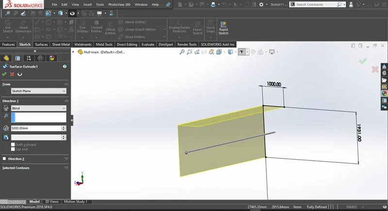
Figure 2.2 Surface Extrude feature been applied
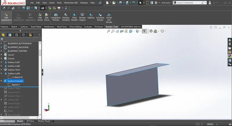
Figure 2.3 3d geomerty created from Surface Extrude
2) Surface Loft
- Surface loft is used to create a 3d sketch with the help of two or more profiles(either 2d or 3d)
- Guide curves can also be used to alter the shape of the loft and make it more defined
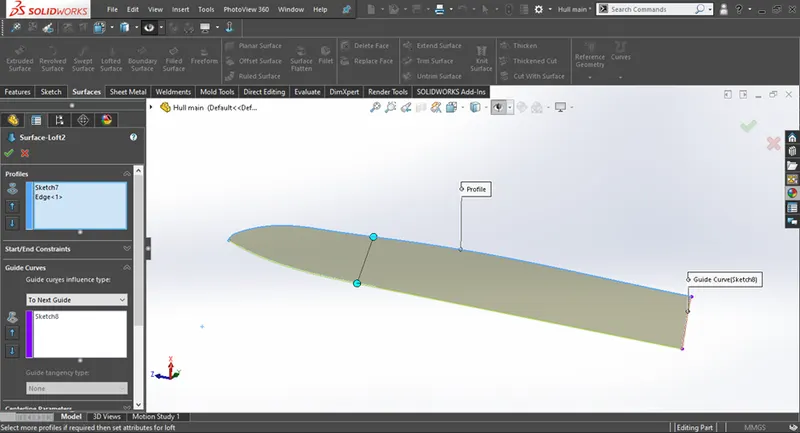
Figure 2.4 Surface loft feature been aplied
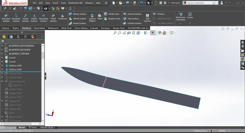
Figure 2.5 3d geomerty created from Surface loft
3) Surface sweep
- Surface sweep is used to create a 3d sketch with the help of a profile and a path
- Guide curves can also be used to alter the shape of the sweep and make it more defined
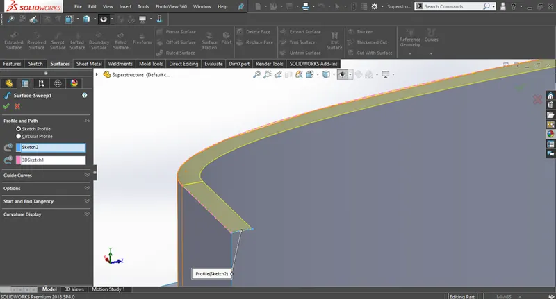
Figure 2.6 Surface sweep feature been aplied

Figure 2.7 3d geomerty created from Surface sweep
4) Surface trim
- Suface trim is used to trim a section of a surafce with the help of another surface or a sketch
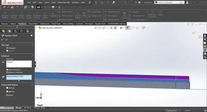
Figure 2.8 Surface trim feature been aplied
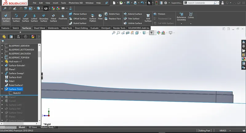
Figure 2.9 After applying Surface trim
5) Surface fill
- Surface fill is used to fill a closed boundary either with the help of sketches or surfaces
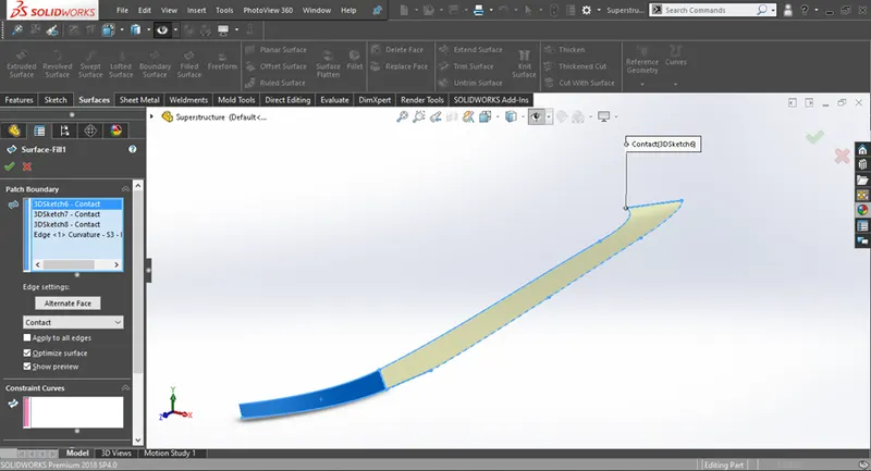
Figure 2.10 Surface fill feature been aplied
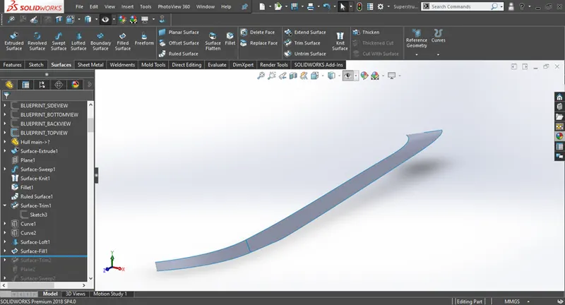
Figure 2.11 3d geomerty created from Surface fill
6) Knit surface
- Knit surface feature helps to knit the gaps exixting between the merging surfaces.
- If the surface is properly knitted then the edges will turn from blue to black as shown below
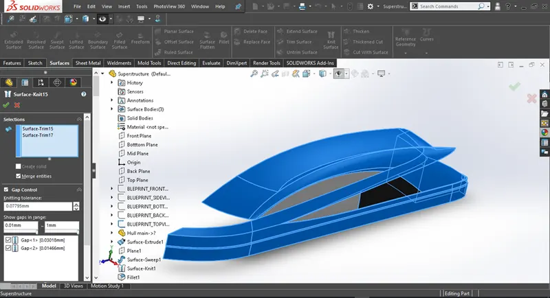
Figure 2.12 Knit surface feature been aplied
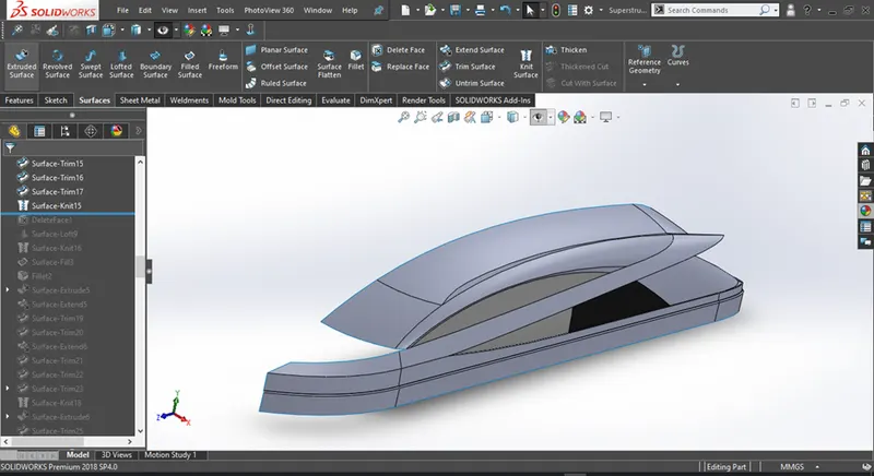
Figure 2.13 After applying Knit surafce
7) Offset surface
- Offset surface basically offsets an already existing surface to a distance required by the user
Figure 2.14 Offset surface feature been aplied
Figure 2.15 After applying offset surface
8) Thicken
- Thicken feature creates a thickened solid from an existing surface
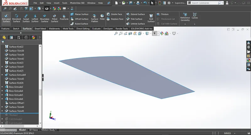
Figure 2.16 Before apllying thicken
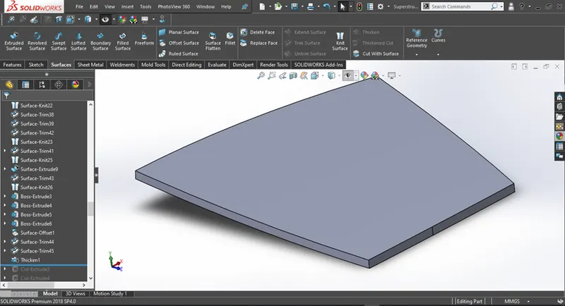
Figure 2.17 After apllying thicken
Design Of Components
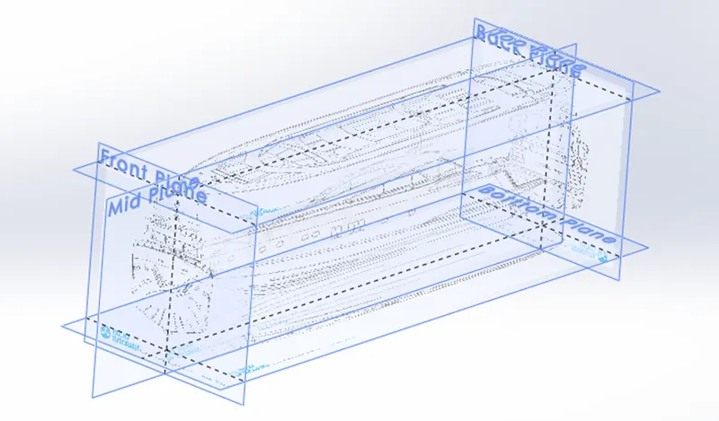
Blueprint
1) Propeller
- A propeller is a device with blades which is attached to a boat or aircraft.
- The engine makes the propeller spin round and causes the boat or aircraft to move.
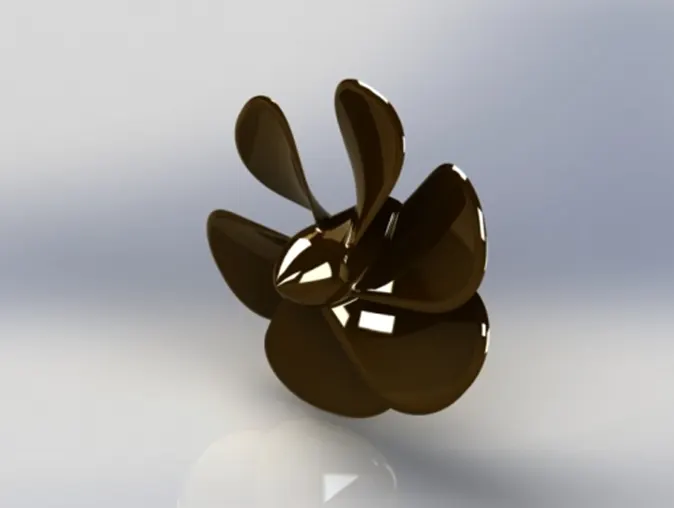
Figure 3.1 Propeller
2) Radar
- Radar (Radio Detection and Ranging) is an instrument that can detect surrounding objects using radio waves.
- Thus, in the maritime world, objects such as ships, buoys or birds can be detected by Radars.
- The use of short-wavelength microwaves allows a very accurate measurement of the direction in which the object is detected and the distance at which it is located
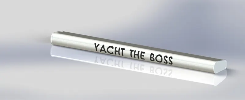
Figure 3.2 Radar
3) Hull
- The hull of a ship is the most notable structural entity of the ship.
- To define the hull, it can be said that it is the watertight enclosure of the ship, which protects the cargo, machinery, and accommodation spaces of the ship from the weather, flooding, and structural damage
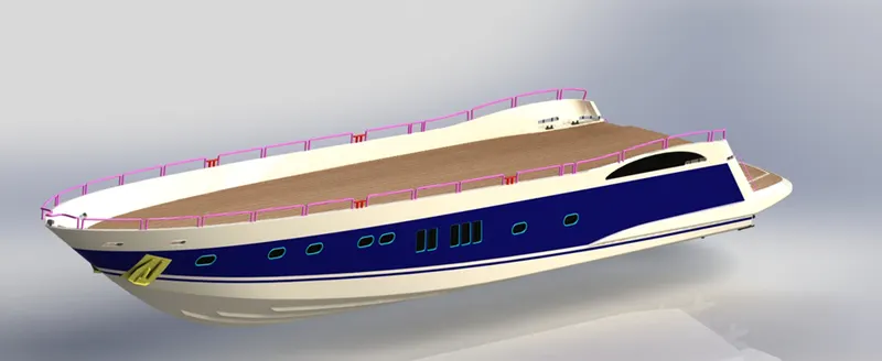
Figure 3.3 Hull
4) Garage door
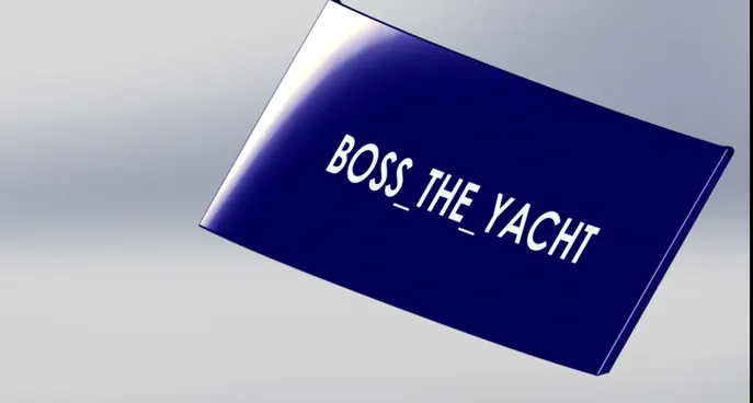
Figure 3.4 Garage door
5) Front seat
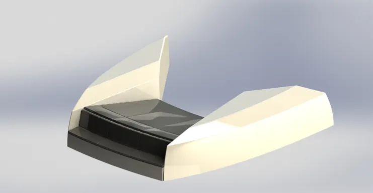
Figure 3.5 front seat
6) Middle seat
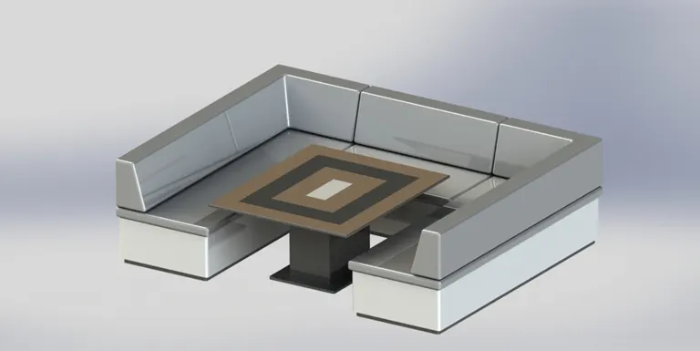
Figure 3.6 Middle seat
7) Rear seat
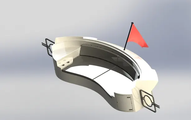
Figure 3.7 Rear seat
8) Superstructure
- superstructure means to add a construction to an already existing structure. In ships this is the name given to the part of the ship that emerges from the deck
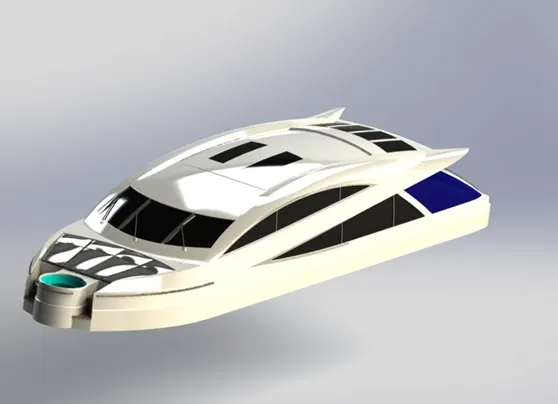
Figure 3.8 Superstructure
9) Radar mast
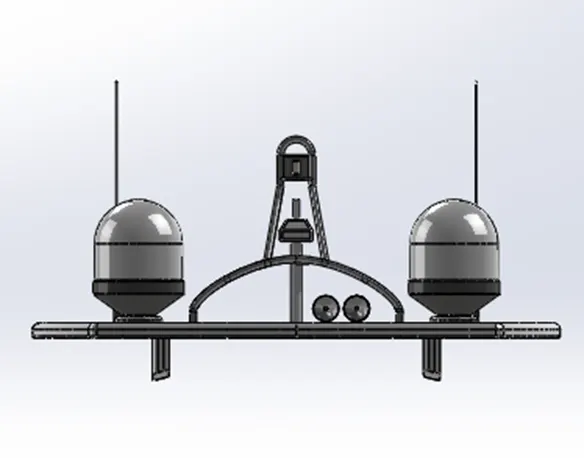
Figure 3.9 Front view Radar mast
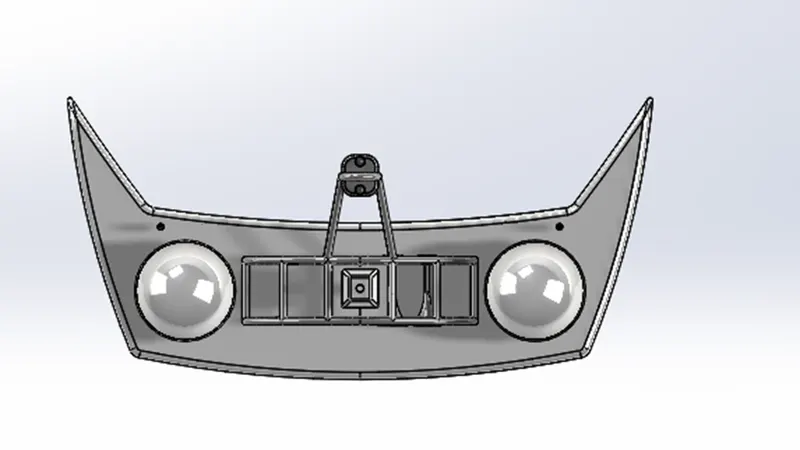
Figure 3.10 Top view Radar mast
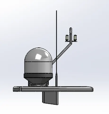
Figure 3.11 Side view Radar mast
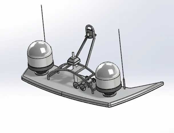
Figure 3.12 Isometric view Radar mast
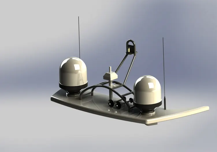
Figure 3.1 Radar mast
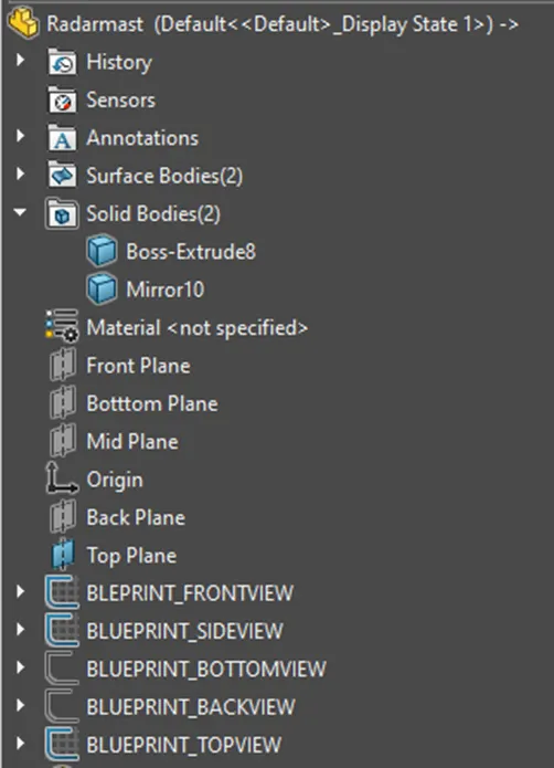
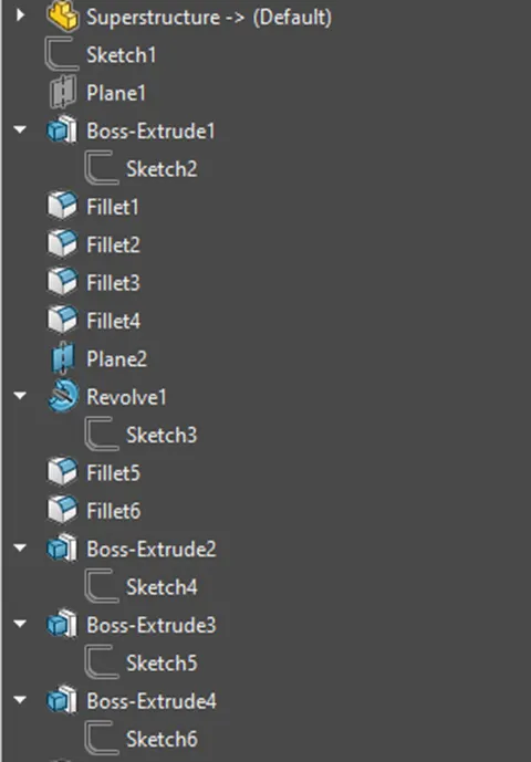
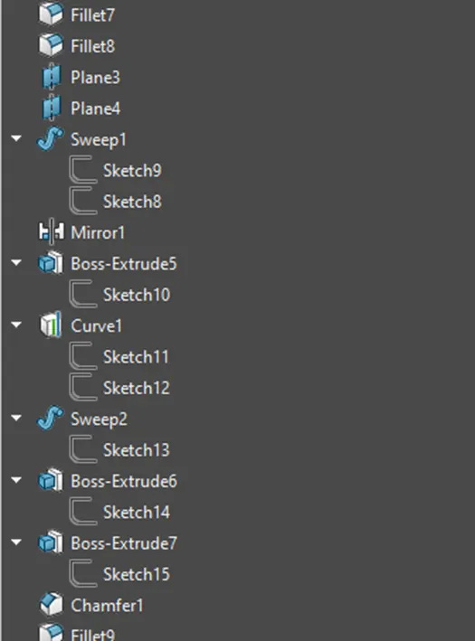
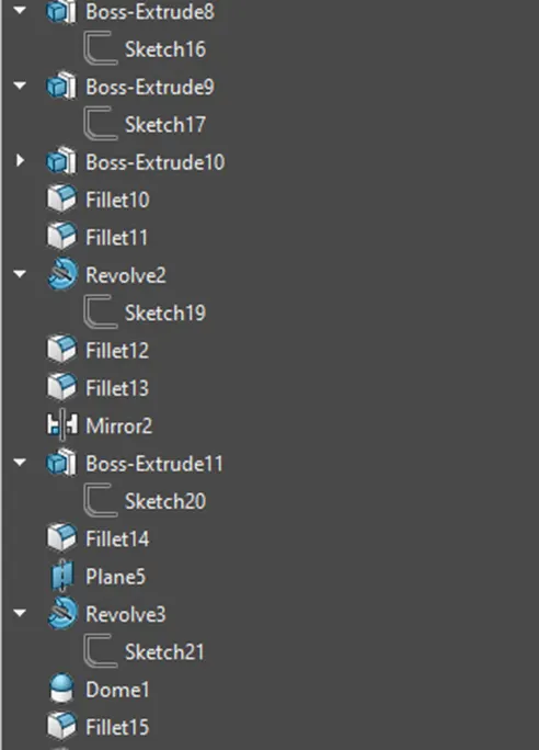
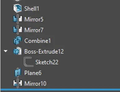
Figure 3.14 feature tree Radar mast
Assembly And Render Of Sunseeker predator yacht
After all the componets have been designed individually in solidwoks, they are all brought together and assembled in solidworks to create the final assembly of the yacht . Since most of the components were designed in reference to the main hull of the yacht they did not require any position change and hence when inserted into the assembly file they were correclty fixed in the required position .Few components required positioning which involved the use few different types of mates. The mates which were used are:
- Coincident mate
- Concentric mate
- Distance mate
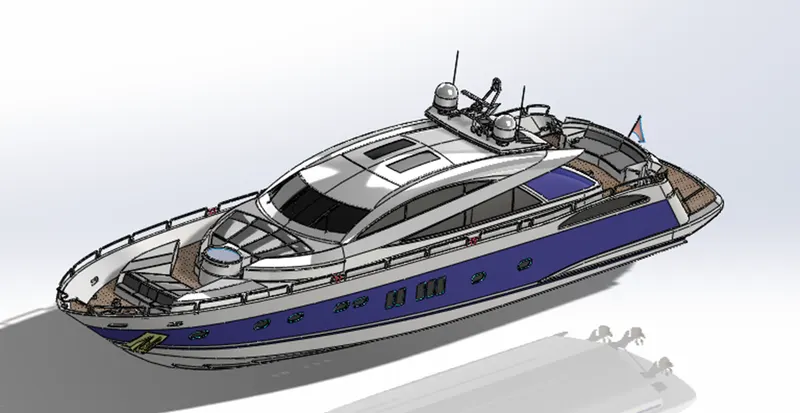
Figure 4.1 Assembled view of yacht
The yacht assembly was then rendered to obtain a realistic look of the assembly
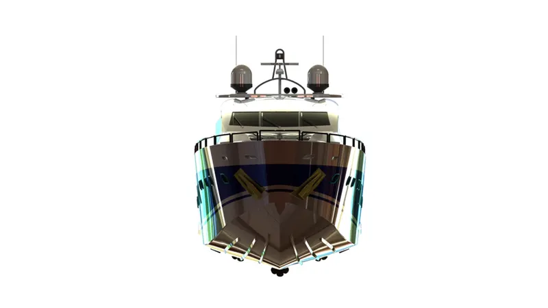
Figure 4.2 Front view of yacht
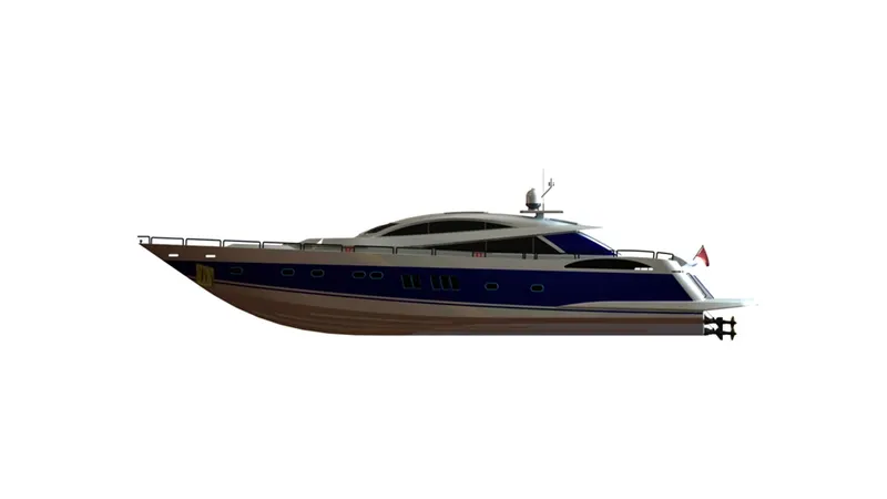
Figure 4.3 Side view of yacht
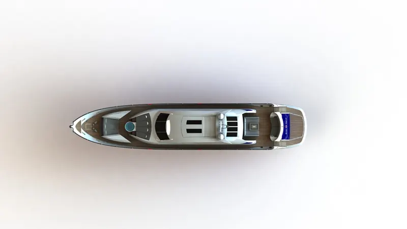
Figure 4.4 top view of yacht
Figure 4.5 perspective view of yacht
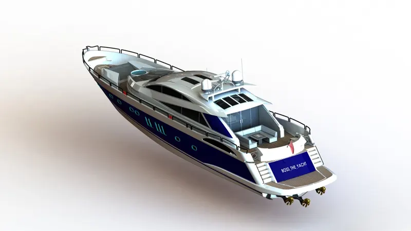
Figure 4.6 perspective view of yacht
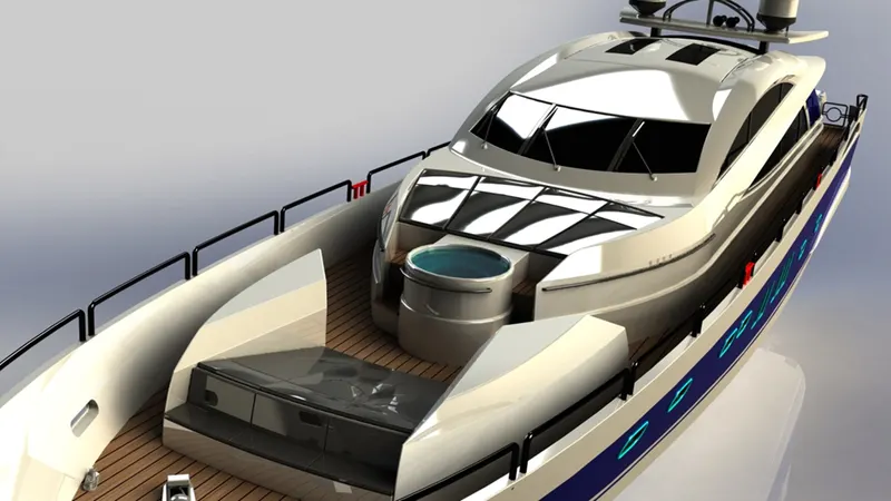
Figure 4.7 detailed view of yacht
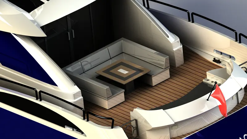
Figure 4.8 detailed view of yacht
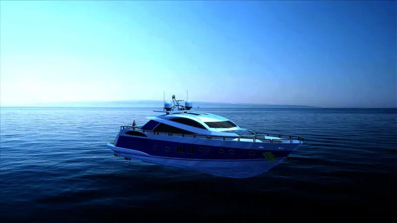
Figure 4.9 Render of yacht with scene
Conclusion:
The components of the sunseeker predator yacht were designed using solid and surface modelling techniques and finally the assembly of the yacht was done. The renders of the yacht were done in solidworks to give us a glance of how the yacht would look in real life.