Photo Realistic Rendering
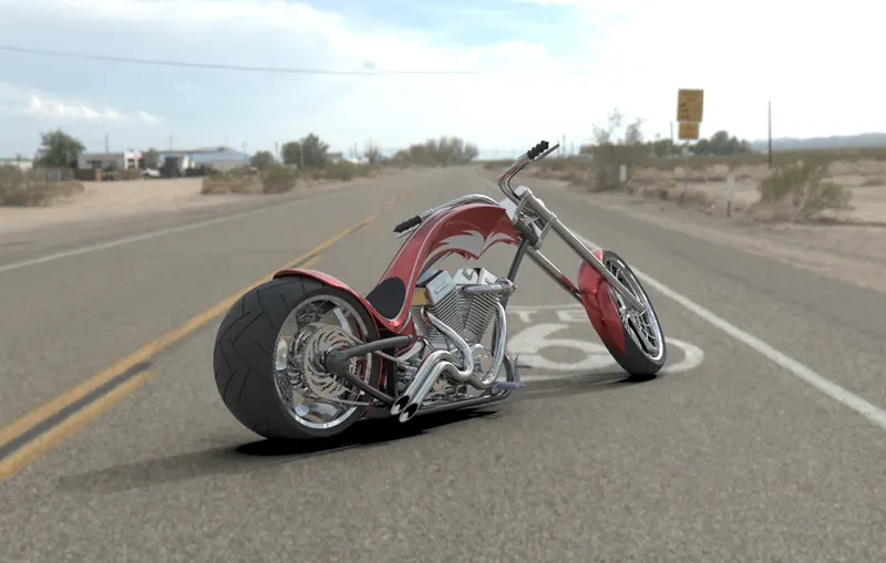
DESIGN ,ASSEMBLY AND RENDER OF AMERICAN CHOPPER
Objective:
- To design and assemble each and every component of the american chopper
- To acquire knowledge about part design and surface design
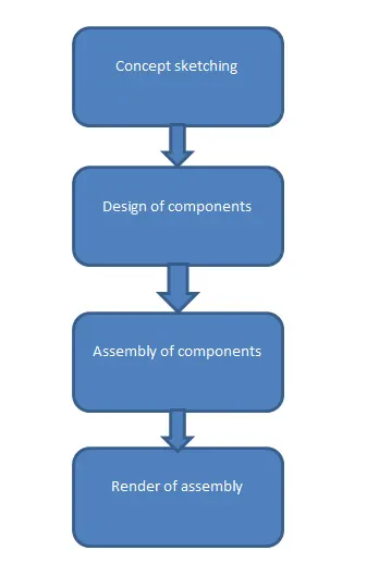
- To understand the flow of process in designing a motorcycle
- To render photo-realistic images of the american chopper
Introduction:
The american chopper is a concept design which boasts a sleek looking body work and a v-twin engine.. The components requires the used of solid and surface design
The components are been designed in the following order:
- Transmission belt
- Kick stand
- Front-fender
- Rear-fender
- Chain
- Oil tank
- Pedal
- Front wheel
- Rear wheel
- Front fork
- Chasiss
- Engine
- Gas tank
Design Methodology:
The choPper is moddled using the bottom-up assembly approach which means that the components are modlled individually and then finally all of the components are assembled
Features And Tools Used In The Design Process:
1) Boss Extrude
- Boss extrude is the most basic and important function in solidworks used to create a solid from a sketch
- It transforms the 2d sketch into a 3d object
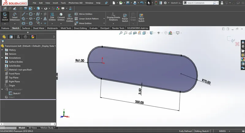
Figure 1.1 Fully defined 2d sketch
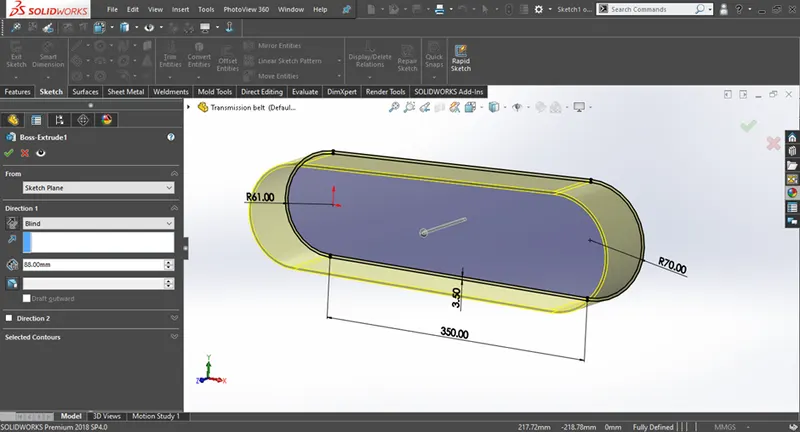
Figure 1.2 Boss Extrude feature been aplied
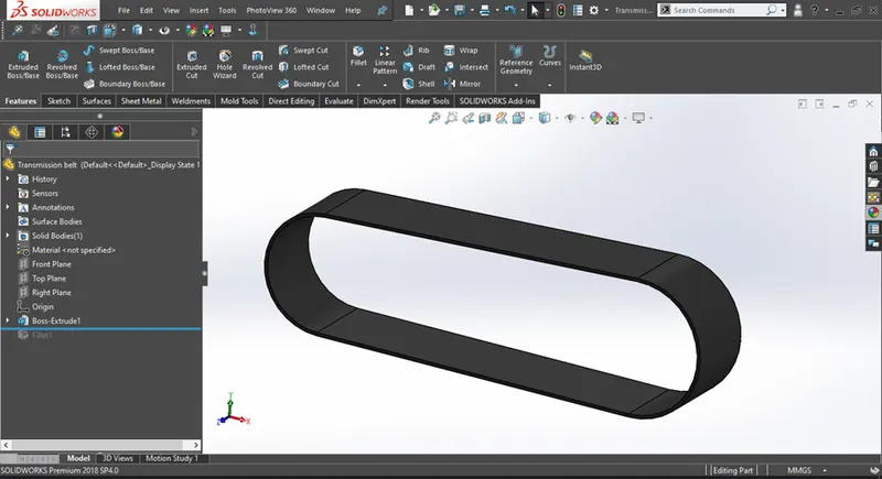
Figure 1.3 3d geomerty created from Boss Extrude
2) Cut Extrude
- Cut extrude is used to remove material from a solid or a surface
- It requires a sketch and a geometry which has to be cut
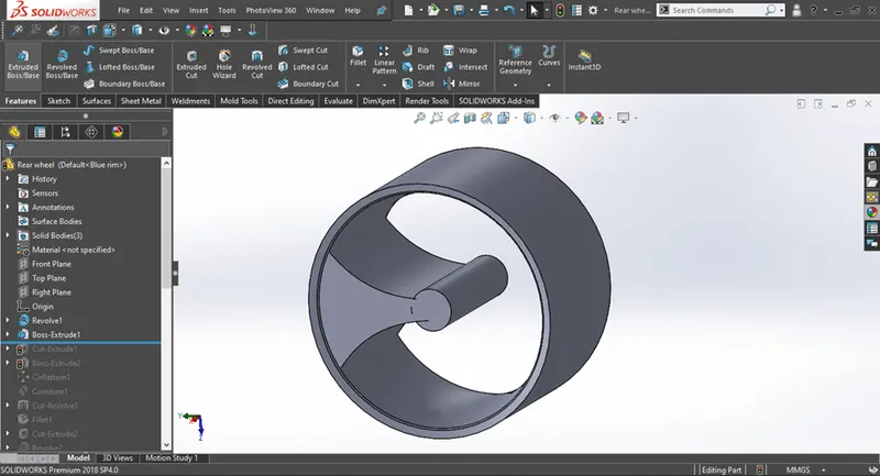
Figure 1.4 3d geomerty to be cut
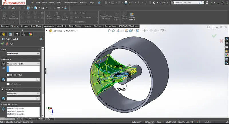
Figure 1.5 Cut Extrude feature been aplied
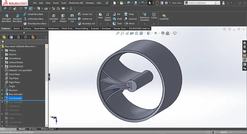
Figure 1.6 Resulting geometry from cut extrude
3) Revolve
- Revolve is used to create solid/surface by revolving a sketch around a given axis
- Based on the selection of axis the revolve shape will also change
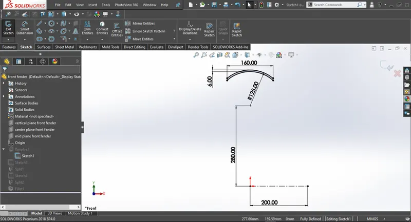
Figure 1.7 Fully defined 2d sketch
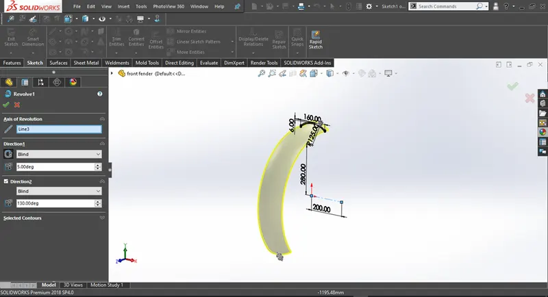
Figure 1.8 Revolve Boss/Base feature been applied
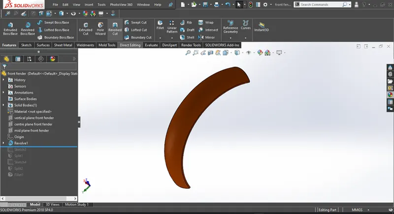
Figure 1.9 3d geomerty created from Revolve Boss/Base
4) Fillet
- Fillet feature is used to round off sharp edges od a 3d model and given it a more cleaner look
- The most commonly used fillet options are constant size fillet and the full round fillet
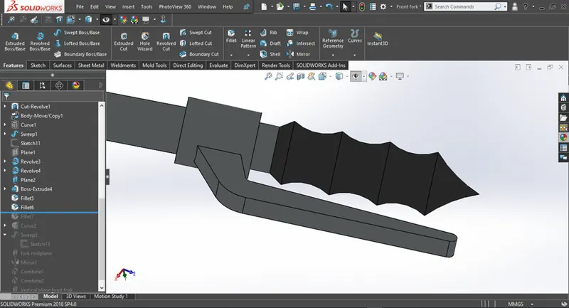
Figure 1.10 model before applying fillet
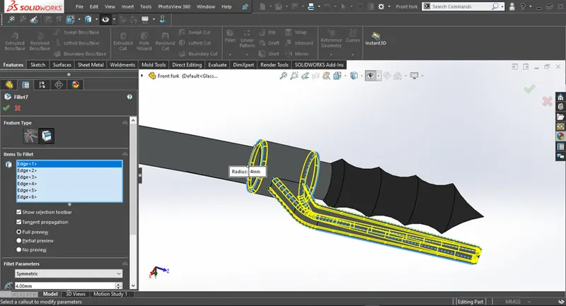
Figure 1.11 Applying fillet to the model
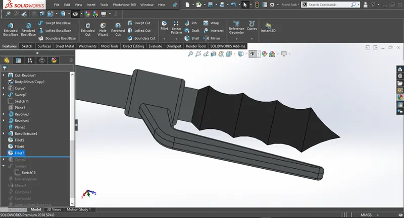
Figure 1.12 Resulting geomertry from fillet
5) Shell
- Shell command is used to make a 3d object hollow by reomving the inner geometry while maintainig a wall thickness as desired by the user
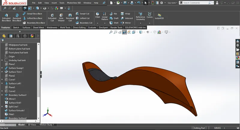
Figure 1.13 Before aplying shell feature
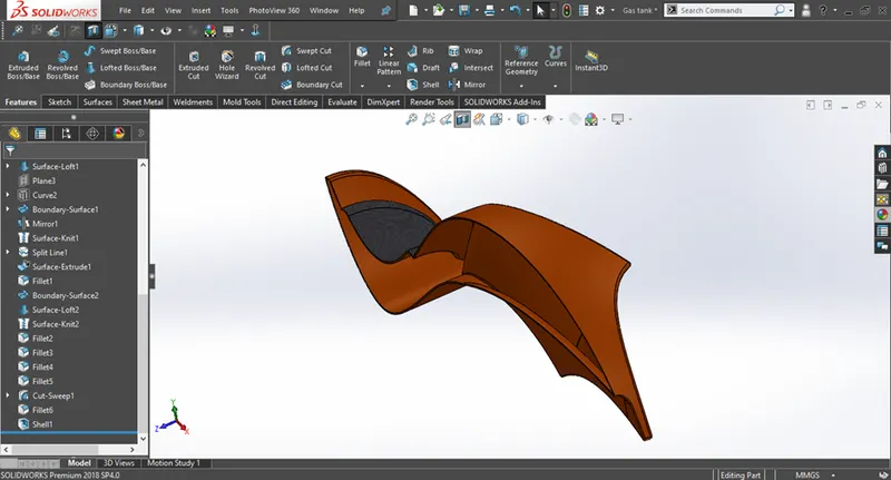
Figure 1.14 After aplying shell feature
6) Dome
- Dome feature is used to create an elliptical or circular profile at the end of a face giving it a nice and smooth profile
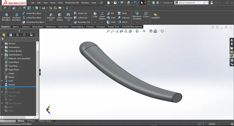
Figure 1.15 Before applying dome feature
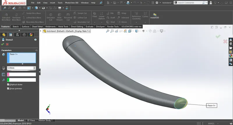
Figure 1.16 After applying dome feature
7) Split
- Split commnd is used to split a 3d object into multiple 3d objects based on skethces provided by the user
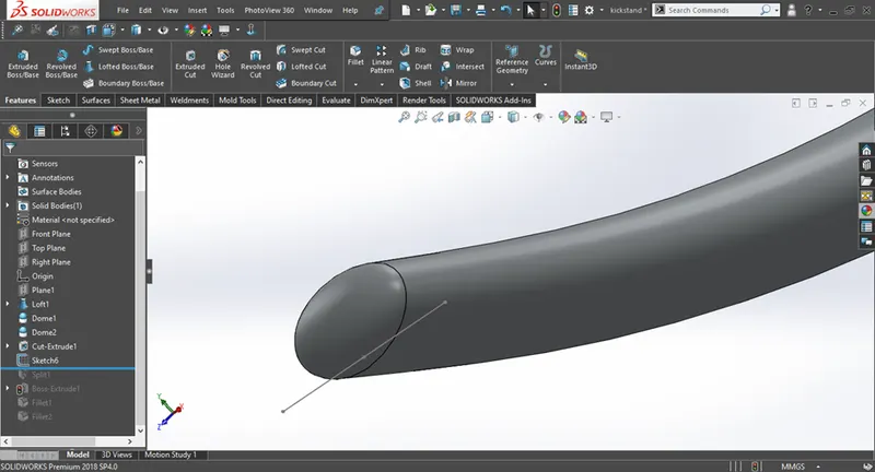
Figure 1.17 2d sketch required to split
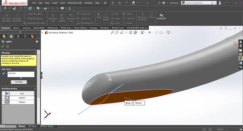
Figure 1.18 split feature been applied
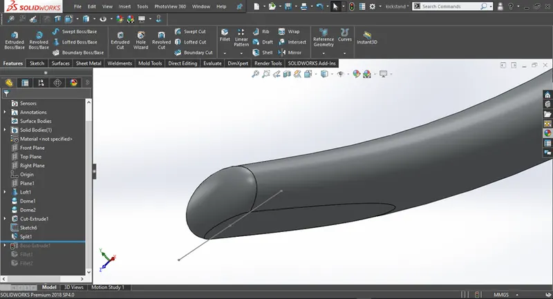
Figure 1.19 Resulting geometry from split feature
8) Combine
- Combine option is one of the most useful features in soluidworks
- It has three options available:
- Add
- Subtract
- common
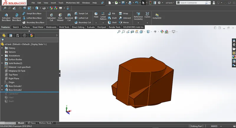
Figure 1.20 Before using combine feature
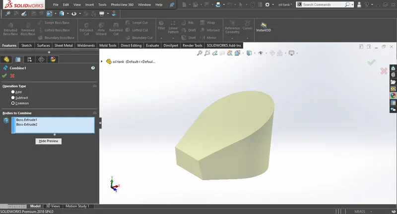
Figure 1.21 After using combine feature
9) Projected Curve
- Projected curves creates a 3d curve based on two 2d sketches provided by the user
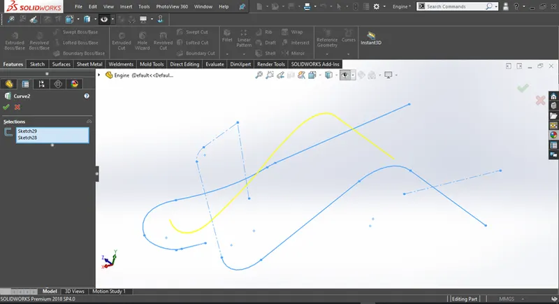
Figure 1.22 Example of projected curve
10) Pattern
- Pattern option is used to create multiple instaces of features or bodies
- The two most commonly used pattern options are linear pattern and circular pattern
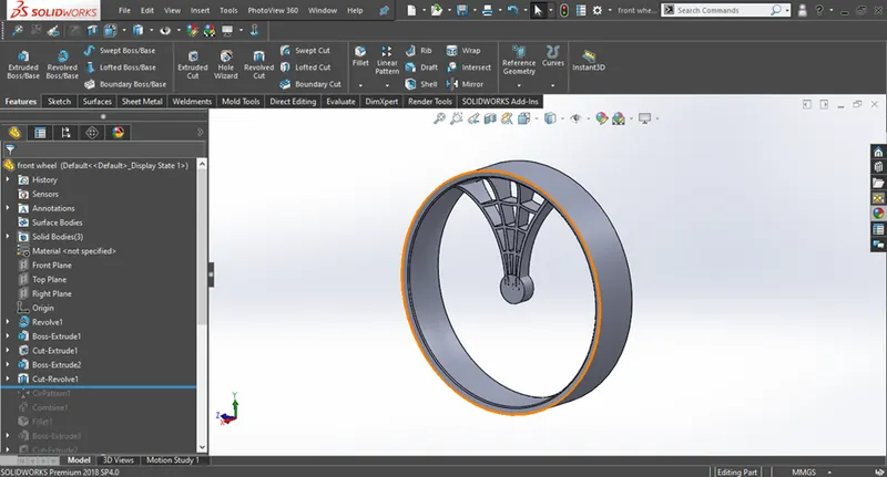
Figure 1.23 Before apllying circular pattern
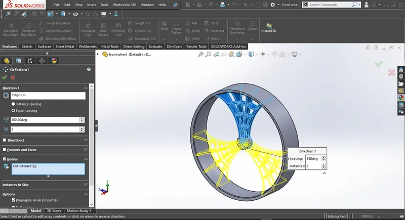
Figure 1.24 circular pattern been applied
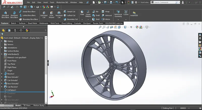
Figure 1.25 Resulting geometry from circular pattern
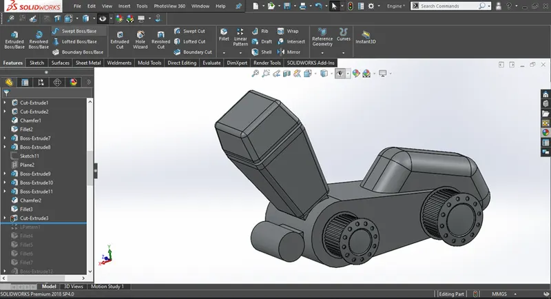
Figure 1.26 Before applying linear pattern
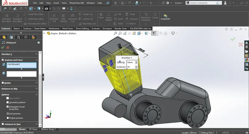
Figure 1.27 linear pattern been applied
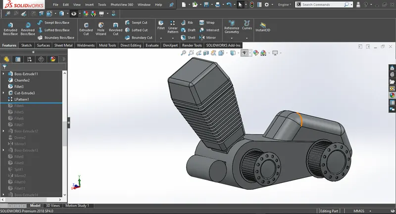
Figure 1.28 Resulting geometry from linear pattern
11) Mirror
- The mirror option helps duplicate a feature or a body based on a plane or a face selected by the user
- The user can create only half of the required geometry and the mirror it to get th required results
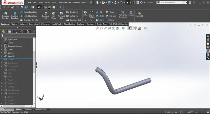
Figure 1.29 Before applying mirror
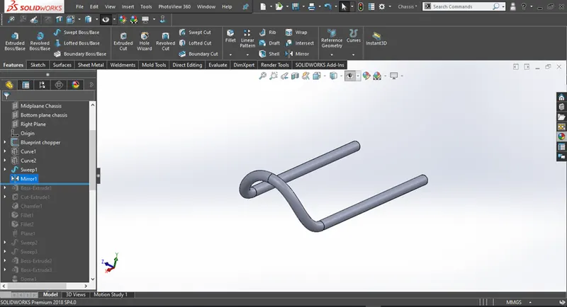
Figure 1.30 Before applying mirror
Design Of Components
1) Transmission Belt
The transmission belt is used to tranfer the power from the driver,which in our case is the motor to the driven,which is the wheel of the vehilce.
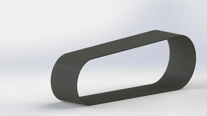
Figure 2.1 Transmission belt
2) Kick Stand
A kickstand helps support a motorcycle when it's parked so it doesn't tip over. Most motorcycles have kickstands that flip out from the side of the bike, some motorcycles have centre kickstands and some bikes are even equipped with both types.
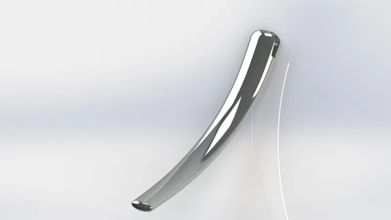
Figure 2.2 Kickstand
3) Front-Fender
Fenders can add style and function to motorcycles. One of the primary functions of a fender is to keep dirt, dust, and road debris away from the wheel and the braking system.it also enhances the look of the bike.
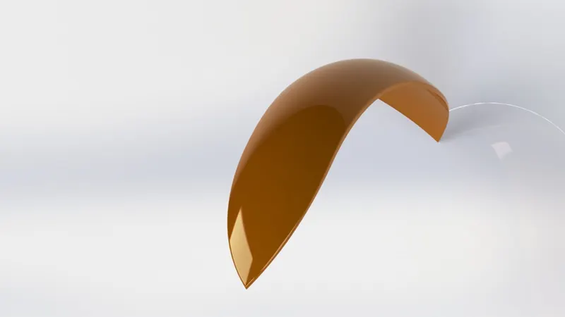
Figure 2.3 Front fender
4) Rear-Fender
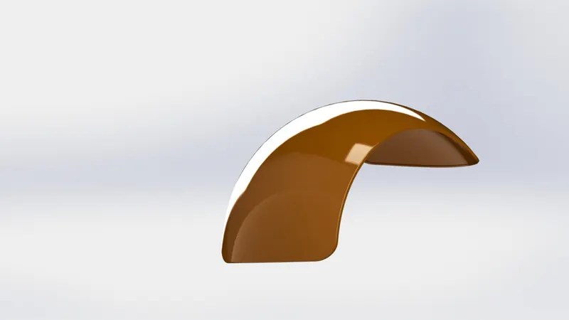
Figure 2.4 Rear fender
5) Chain
Chain consists of many rollers and links put together which helps transfer the power from the engine to the sprocket which finally drives the wheels
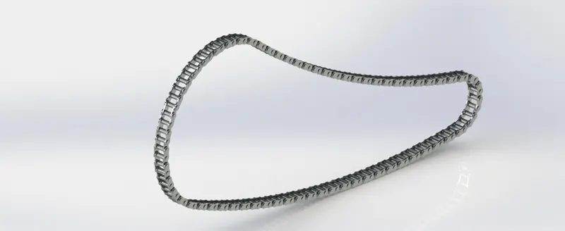
Figure 2.5 Chain
6) Oil Tank
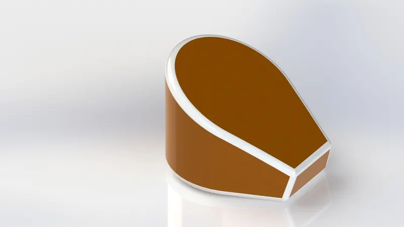
Figure 2.6 Oil tank
7) Pedal
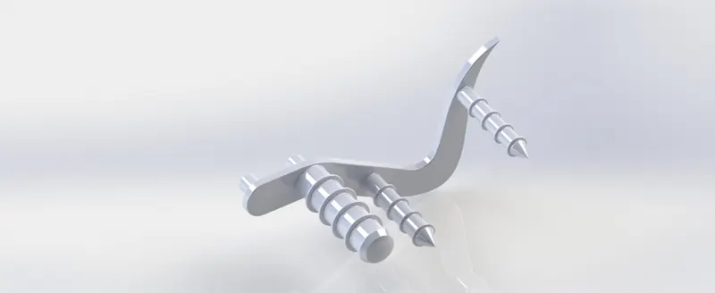
Figure 2.7 Pedal
8) Front Wheel
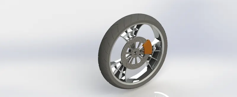
Figure 2.8 Front wheel
9) Rear Wheel
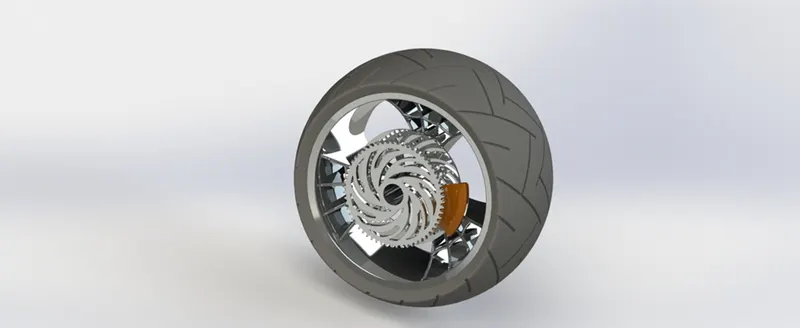
Figure 2.9 Rear wheel
10) Front Fork
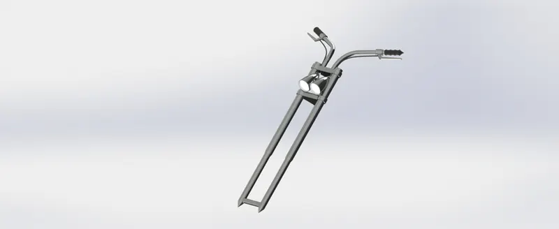
Figure 2.10 Front fork
11) Chasiss
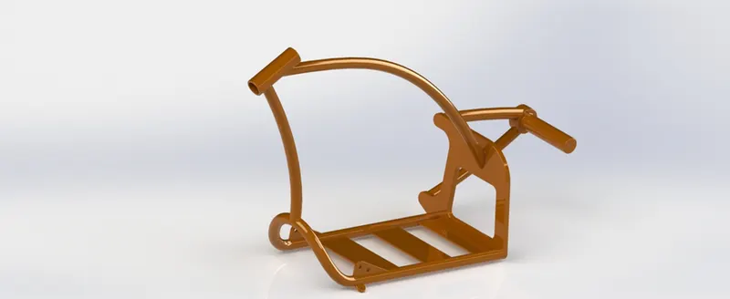
Figure 2.11 Chassis
12) Engine
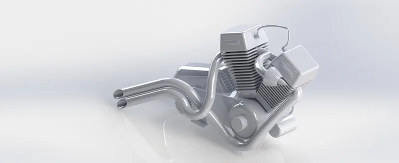
Figure 2.12 Engine
13) Gas Tank
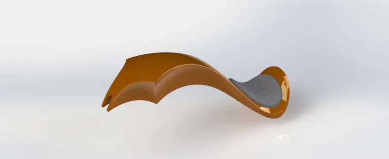
Figure 2.13 Gas tank
Assembly And Render Of American Chopper
After all the components have been designed individually in solidwoks, they are all brought together and assembled in solidworsk to create the final assembly of the bike . The assembly process involves the use of many different types of mates. The mates which were most commonly used are:
- Coincident mate
- Concentric mate
- Parallel mate
- Width mate
- Limit mate
- Distance mate
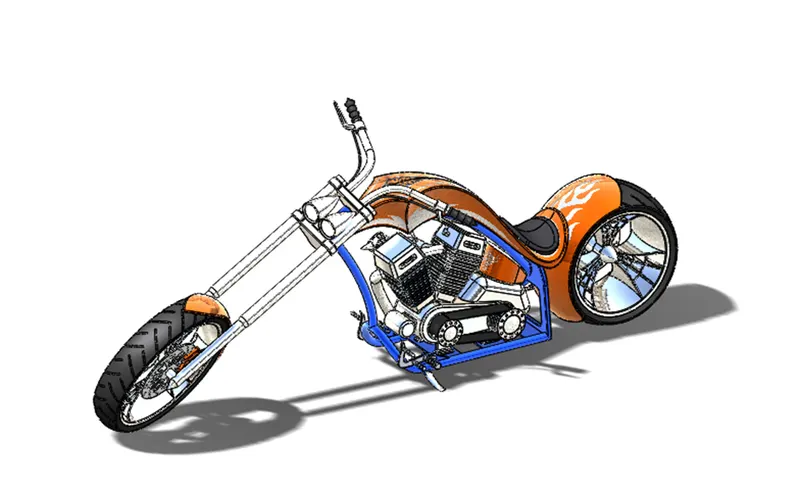
Figure 3.1 Assembled view of american chopper
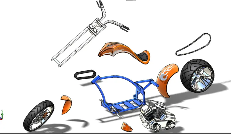
Figure 3.2 Exploded view of american chopper
- After the final assembly of the american chopper the environment, scenes and the camera angles where changed accordingly to obtain the best possible render of the motrocycle in different views
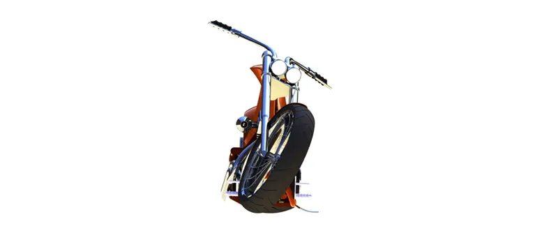
Figure 3.3 Front view of American chopper
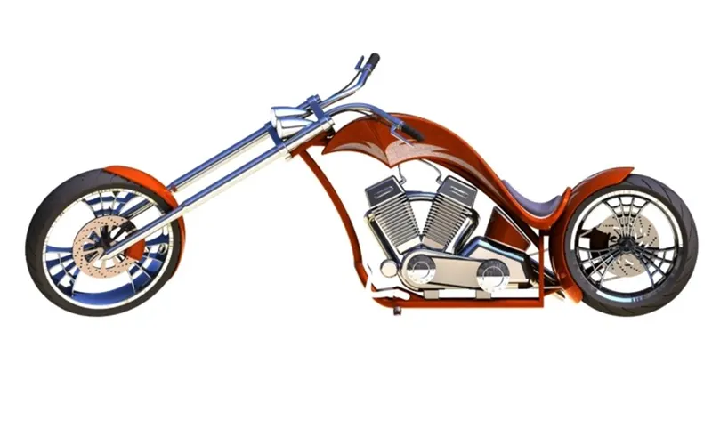
Figure 3.4 Side view of American chopper
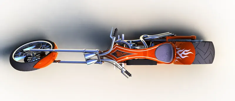
Figure 3.5 Top view view of American chopper
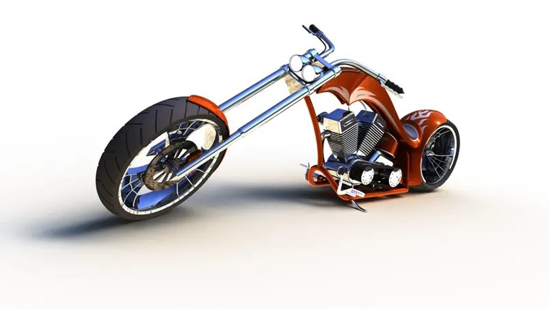
Figure 3.6 Perspective view of American chopper
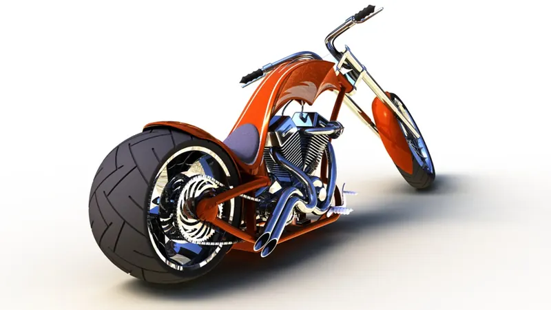
Figure 3.7 Perspective view of American chopper
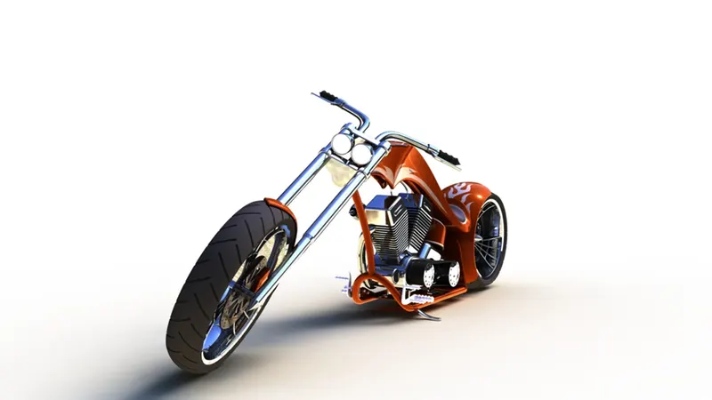
Figure 3.8 Perspective view of American chopper
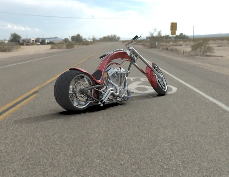
Figure 3.9 Render of American chopper in visualize
Conclusion:
The components of the american chopper motorcycle were designed using solid and surface modelling techniques and finally the assembly of the motorcycle was done. The renders of the chopper were done in solidworks to give us a glance of how the motorcycle would look in real life.