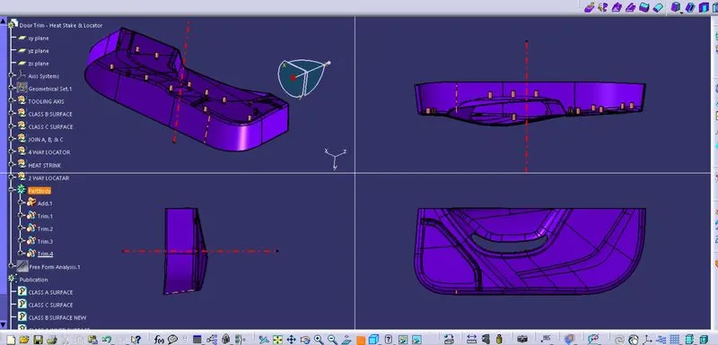
Week 9 - Project 1 - Door Trim Lower with Engineering Features
Create the Door Trim Lower Plastic component through the given Class-A surface. To begin with, the tooling axis for the given Class-A Surface should be created meeting the requirements of the draft angle and at the end perform the Draft analysis on the model.
Create the Heat Stakes and the locators considering the design rules mentioned in the video for the door applique.
AIM:
- To Create the Door Trim Lower with Engineering Features Component from the given Class-A surface.
- To Create the tooling axis for the given Class-A Surface meeting the requirements of the draft angle.
- Creating class B surface by using offset command.
- Fixing class B offset surface making into a single part.
- to create a class C surface with a class A surface as a reference.
- To perform the Draft analysis on the model.
- creating a 4-way locator in this door trim considering all design rules.
- creating a 2-way locator to arrest the moment of freedom
- creating a number of heat stakes for each point.
- creating tooling axis and checking for draft analysis if whether the feature is clearing or not.
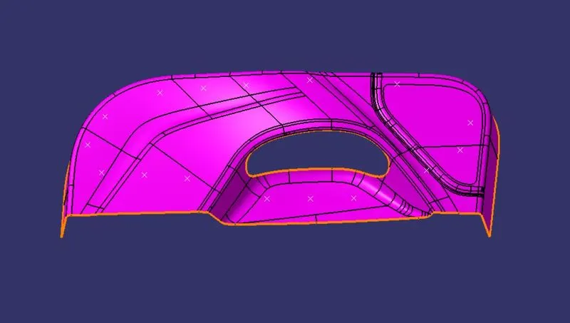
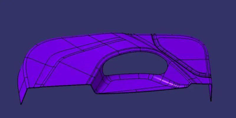
CLASS A SURFACE
Class A surface is shown below for better visual clarity.
TOOLING AXIS CREATED WITH THE REFERENCE OF CLASS A SURFACE
The Tooling Direction is basically the direction that the mold pulls apart. The mold is built in two separate pieces, basically. You have a Cavity side and you have the Core side. The Core pulls apart from the Cavity, the Dye line or the Tooling Direction.
Creation of Class B:
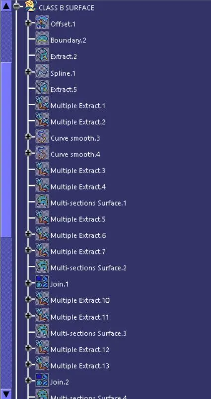
- Now for Class B creation, we have extracted surfaces from Class A and untrimmed them to obtain the original parent surface.
- These surfaces are then offset to the required thickness.
- After offsetting, all the surfaces are trimmed into the required shape.
- Required fillets are given to the surfaces.
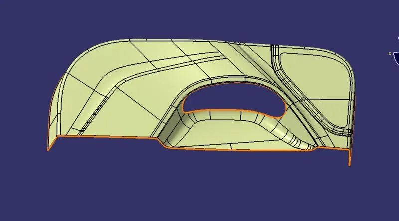
C class surface :
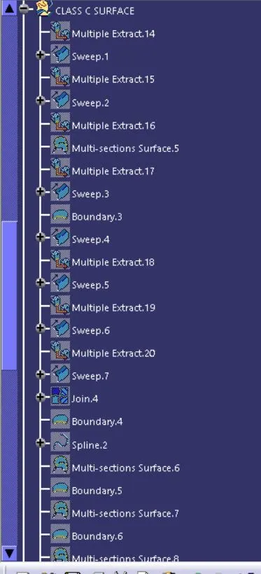
Class C Surface has swept along the boundary CLASS A surface with respect to the tooling axis direction with a draft angle of a maximum 3 degrees minimum of 0.5 degrees.
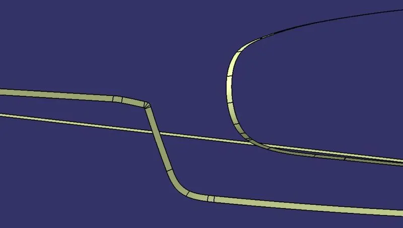
number of sweep command is used to create this class c surface
class c was created with the help of a sweep
and show bellow
also, ensure that class c should be pass 3 degrees of draft angle
complete A, B, AND C are shown in the join
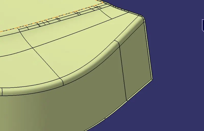
some image is shown below for a clear understanding of how the component is looks.
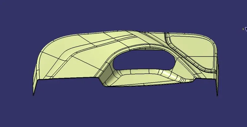
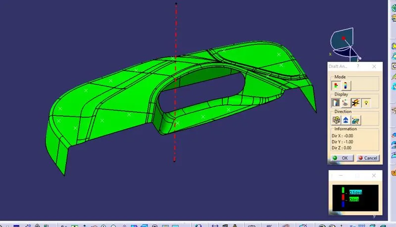
Draft analysis :
The Draft Analysis allows the user to easily analyze a part for a proper draft angle. A Draft Angle describes the amount of taper for molded or cast parts perpendicular to the parting line. Find the Draft Analysis in the Tools tab. Draft Analysis is applicable for 3D part models.
The draft analysis button within CATIA V5 will help you quickly gather the draft angle on multiple surfaces without the need for tedious manual measurements. Here is a quick rundown of how the icon works when you have a given die direction.
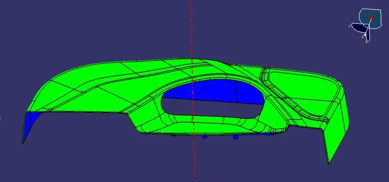
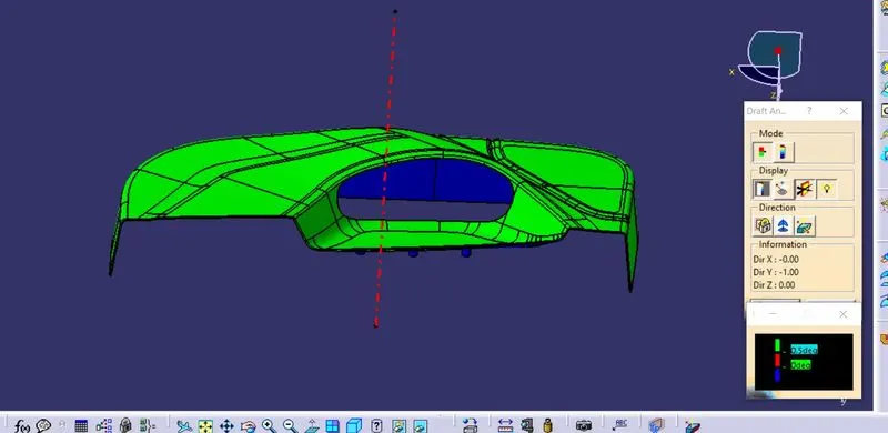
- Before going to drat analysis go to customized view parameter >under mesh >check material and then click ok.
- Now for draft analyses go to insert » analysis » feature draft analysis.
- Use the compass to define the draft direction.
- In the color, the scale changes the draft angle to 3 degrees.
- The component changes to green as an indication of the passing draft angle.
- Use a running point to check the angle on the component.
CLOSED BODY IS SHOWN BELLOW
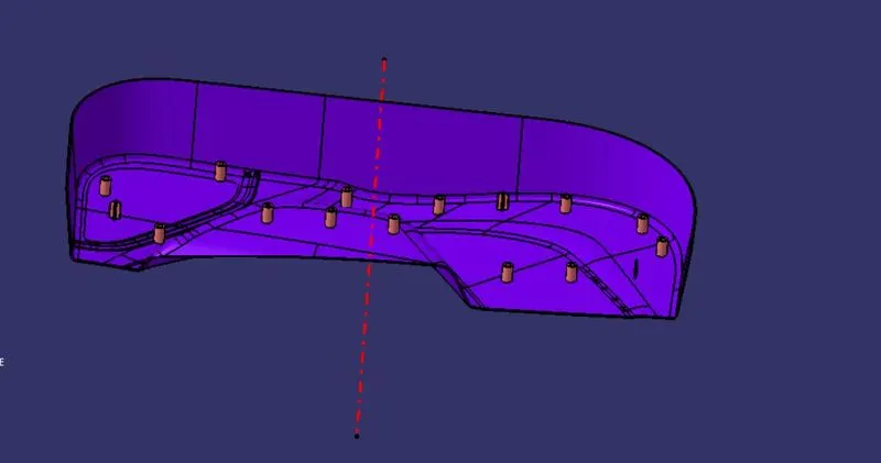
CREATING 4-WAY LOCATOR
- in the cad I made two 4-way locators one on left and another on right.
- then creating two-way locator to arrest some more freedom
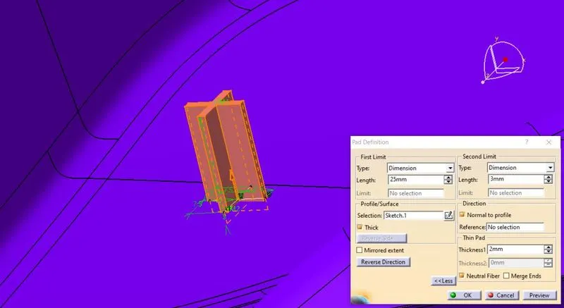
creating the sketch and pad the stretch for 25 mm on one side and 3 mm on another side and check they thick using reference surface as TOOLING AXIS
DRAFT AXIS IS SHOWN BELLOW
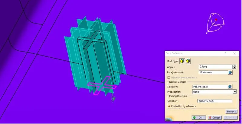
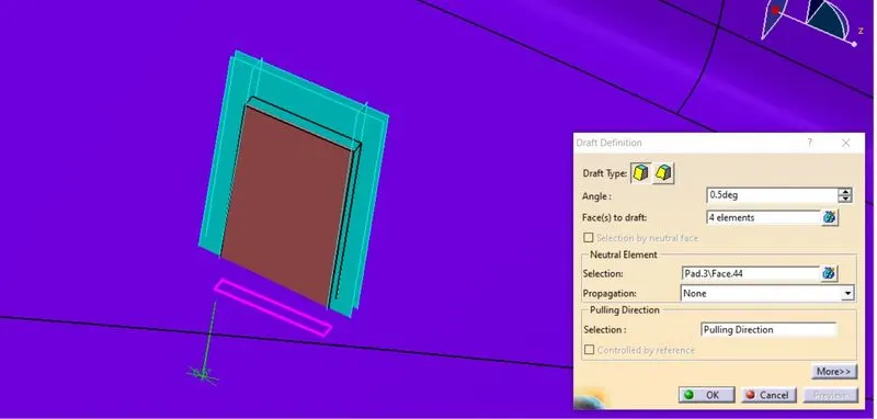
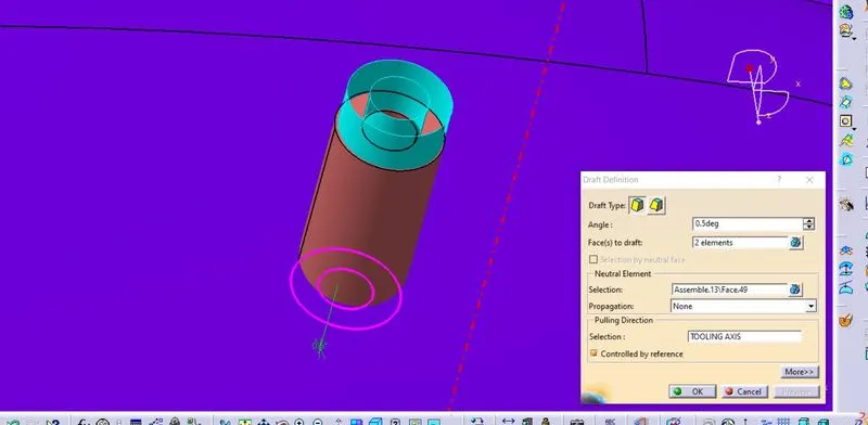
FOR THIS 4-WAY LOCATOR draft has given of .5 deg neutral element as base of the pad and pulling direction as TOOLING AXIS
CHAMPER FOR 4-WAY LOCATOR
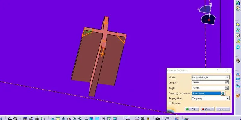
CHAMPER SIZE IS SHOW IN THIS IMAGE
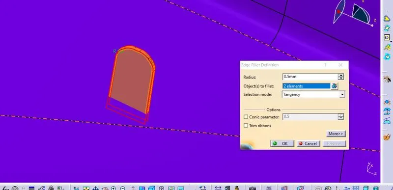
EDGE FILLET USED FOR ALL FOUR SURFACE
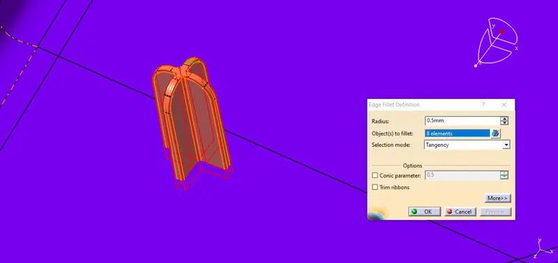
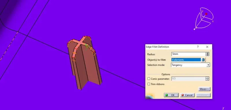
EDGE FILLET is given for all the faces to get rip of shape edges
2-WAY LOCATOR
in same wy 2-way locator has been created
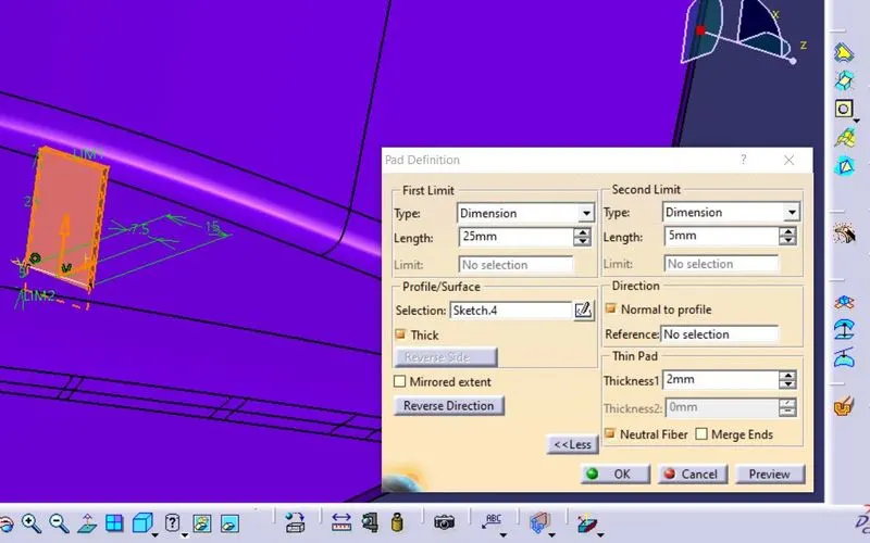
draft image is shown below for 2-way locator
EDGE FILLET IS SHOWN BELOW
HEAT STAKES
creation of heat stakes is shown below
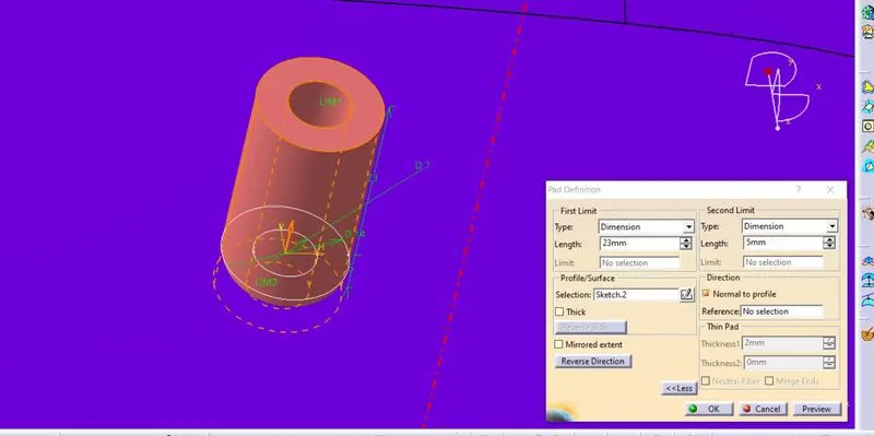
draft for heat stakes
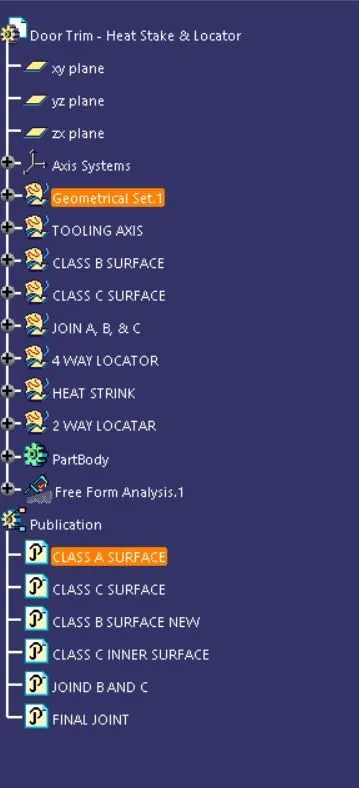
Tree Structure
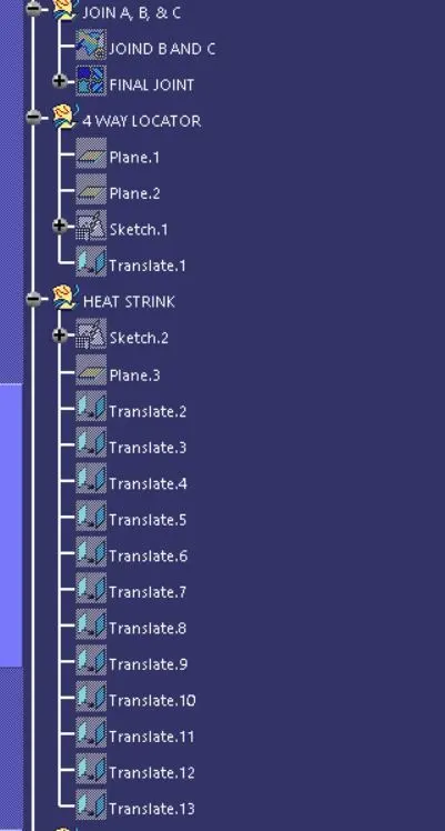
sample images are shown for clarity