Week 9 - Project 1 - Door Applique Design with Engineering Features
AIM:
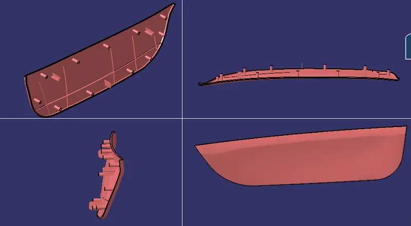
The purpose is to model a toolable solid CAD model from the given class A surface of the Door Applique and create engineering features like ribs, heat stakes and locators on the B-Surface following the design rules.
PROCEDURE:
- Component Study and Tooling Axis Decision
- The model is observed in all 3 directions to decide the best tooling axis direction in order to manufacture the part at a cheaper cost.
- Usually the holes or the flat surfaces are of primary concern to decide the tooling axis. The tooling axis is chosen in such a way that the above mentioned features are also toolable along its direction.
The given class A surface of the Door Applique was checked along Y-axis which is perpendicular to the surface. Since most of the part was visbile when viewed along Y-axis, it can be considered as the tooling axis. However a draft analysis has to be performed to verify if it's the right tooling direction.
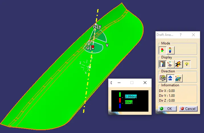
From the above picture, it is evident that the Y-axis can be considered as the tooling axis.
2. A-Surface Correction
The given class A surface has features like styling fillets which are uneven and not parametrized, uneven surfaces which couldn't be joined together properly and surfaces which are uneven. Hence few corrections were made and which can be suggested to the Class-A designer for modifications. Also the class A surface didn't have side walls which were also created to form a modified class A surface.
Before After
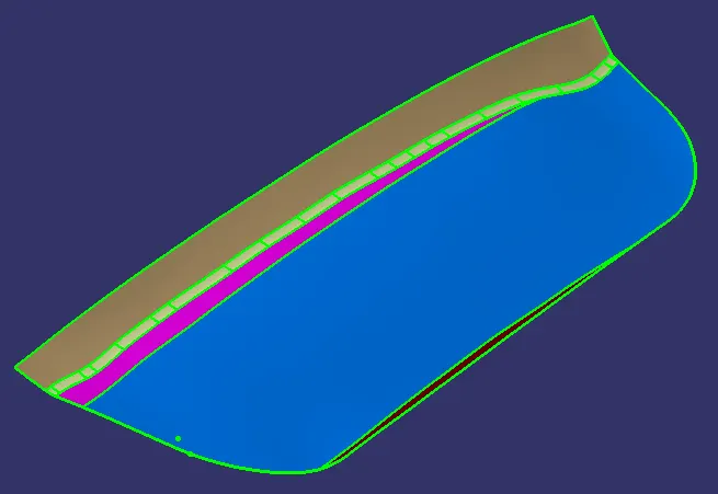
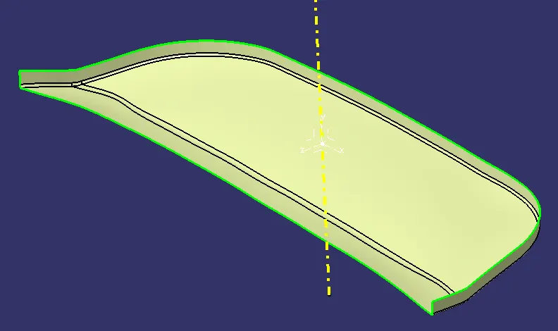
- Firstly, the surfaces were untrimmed, extrapolated and trimmed against each other.
- Then a styling fillet with radius 18mm was created to match the exisitng fillet.
- Finally the side walls were swept outwards for a draft angle of 3 degrees along the tooling axis.
- These surfaces were joined together and filleted for a radius of 2mm along the edges to form the final class A surface as shown in the picture on the right side.
3. Draft Analysis
- Draft Analysis was performed on the modified class A surface to analyze if the component is toolable along the tooling axis.
- Feature Draft Analysis (Analysis> Feature Draft Analysis) option is used to perform draft analysis on the component.
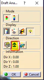
- The compass is placed on the created tooling axis using the option in the Draft Analysis tab as shown below.
- Next the component is chosen to perform the draft analysis. The maximum draft angle is chosen to be 3 degrees (standard value).
- The parts highlighted in green have draft angles from 0 to 3 degrees.
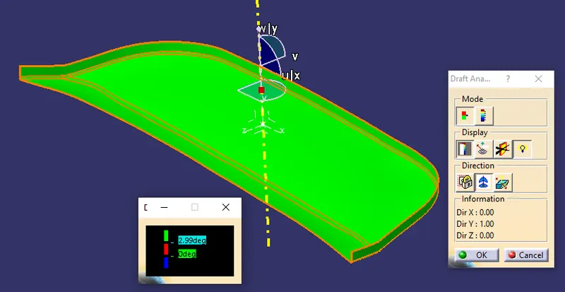
Hence Y-axis can be considered as tooling direction for the modified class-A surface.
4. B Surface Creation
- Before creating the B surface, the model is studied to split the whole part into multiple parts for easier modelling. The whole B surface was divided into 4 parts as shown in different colors.
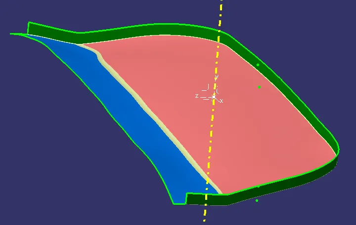
- Each surface present in each of the parts mentioned above was first extracted from the given class A surface.
- Then these are untrimmed and extrapolated to create an intersection between them.
- These are then offset 2.5 mm from the class A surface, trimmed w.r.t each other and filleted to form the B surface (base of the actual component).
- Style Fillet Radius: 18-2.5=15.5 mm ; Edge Fillet= 0.5 mm (minimum value)
6. C Surface Creation
- Boundary of the class A surface is created as highlighted in green in the picture below.
- The surfaces adjacent to the boundary were then extracted to use them for the sweep option in the next step.
- Then the boundary was swept perpendicular to the tooling axis. The following sweep option was used.
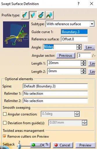
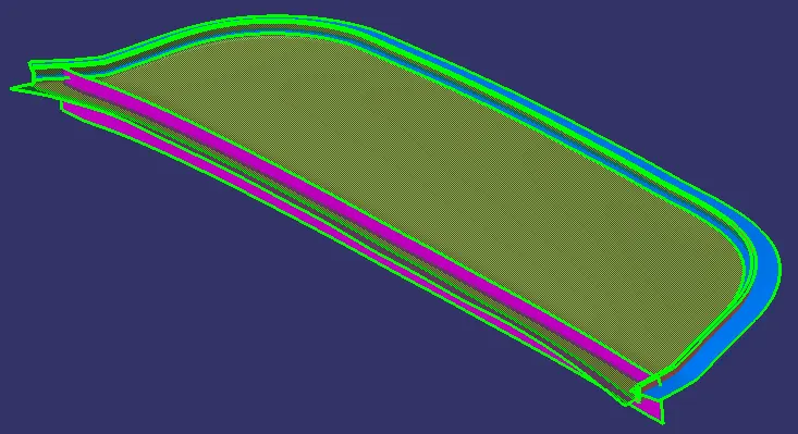
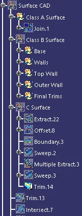
- The part has 2 class C surfaces one on the front along the tooling axis direction with 3 degrees draft angle and another perpendicular to the tooling direction. Hence 2 step trimming was done to achieve the final design.
- C-surface w.r.t A and B surface is shown below.
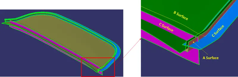
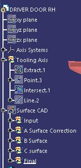
- Finally all 4 surfaces were trimmed against each other to form the final surface CAD model.
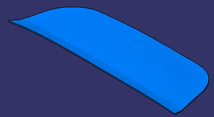
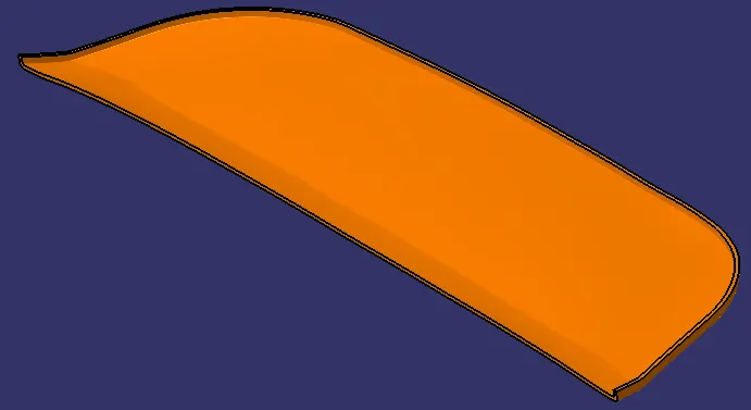
The following figure shows the surface CAD models generated from the original and modified class-A surface.
ORIGINAL MODIFIED
7. Part Model Creation
- With the surface model obtained in the previous step, the solid model is obtained by using closed surface option in the part workbench.
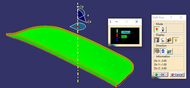
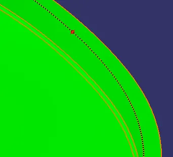
- Draft Analysis was performed for the solid part to check the manufacturing feasibility. Draft Analysis results in filleted region is shown on the right side picture.
8. Rib Modeling
Since the given part is bigger in size there is a huge possibility of warping. Hence ribs are to be provided along its face to prevent this defect and also to increase the component strength. To prevent the plastic defects like sink marks from happening during the IM process, different sets of design rules are to be followed by the product designer namely-
- Minimum Rib Base Thickness- 0.4 x Part Thickness
- Minimum Draft Angle- 0.5° each side of the rib
- Maximum Rib Height- 5 x Part Thickness
- Minimum Rib Tip Thickness- 0.75 mm
- Fillet Radii- 0.25 Maximum
- Spacing between Ribs- (Maximum: Rib Height/2); ((Maximum: Rib Height/3)
- Rib root thickness- 1.3 x Part Thickness
The above set of rules are followed to create the ribs on the B-surface of the coin holder.
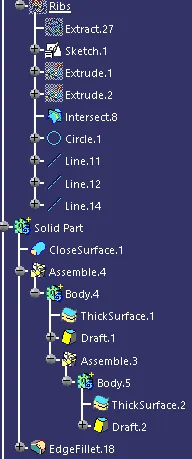
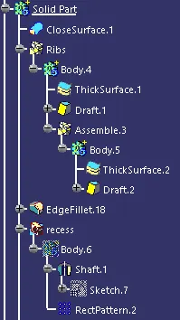
- A sketch was created initially on the extracted B-surface based on the design rules.
- Then a surface was extruded from the sketch along the tooling axis and thick surface option from the part workbench was used to create the solid ribs.
- The rib surfaces along the tooling direction were then drafted for 0.5°.
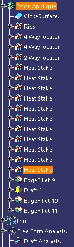
- Then these ribs were assembled to the main part through boolean operation to form the final part.
- Then these ribs were split using the offseted surface extracted from the B-surface.
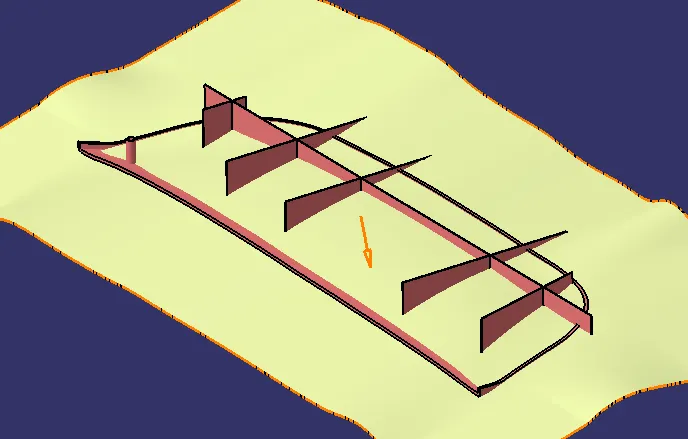
- Finally the surfaces of the ribs were edge filleted at the part-rib interface to arrive at the final design.
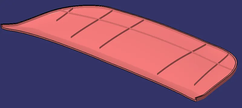
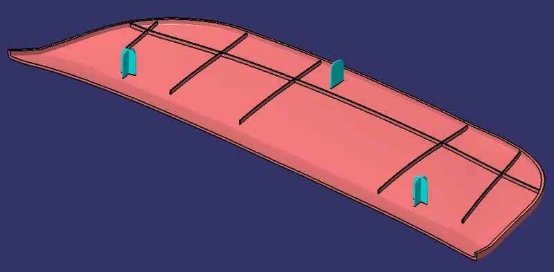
The ribs determine the positions of the heat stakes and locators.
9. 2-way and 4-way locators
Every component has 12 degrees of freedom (DOF) comprising of 6 translational and 6 rotational DOF.
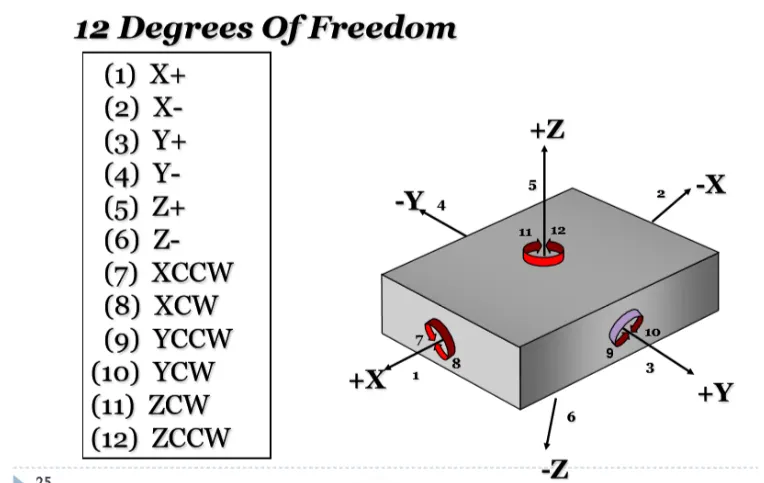
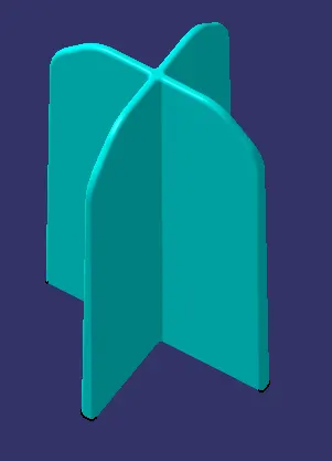
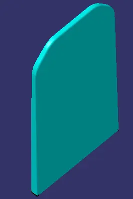
The plastic component is generally designed based on 3-2-1 principle to arrest unwanted DOF. Therefore locators are used for the purpose of arresting almost all degrees of freedom leaving behind one for part assembly. There are 2 types of locators-
- 4 way locators- These arrest 4 translational DOF perpendicular to the component orientation, say +x,-x,+y,-y.
- 2 Way locators- These arrest only 2 translational DOF perpendicular to the component orientation, say+x,-x or +y,-y.
To arrest rotational DOFs of the plastic part, these locators are provided at different points in the part. Two 4 way and one 2 way locators are provided to arrest the rotational DOFs.
- The dimensions length x width of the 4 way locators are 15 mm x 15 mm and 2 way locators is 15 mm.
- Thickness- 1.3 mm
- Height- Depending on the extension needed above the mating surface.
- Interface Fillet Radii- 0.25mm
- Entry Chamfer - 3mm x 45°
- General Fillet Radii- 3mm
- Draft Angle-0.5°
4 Way Locator 2 Way Locator
10. Heat Stakes
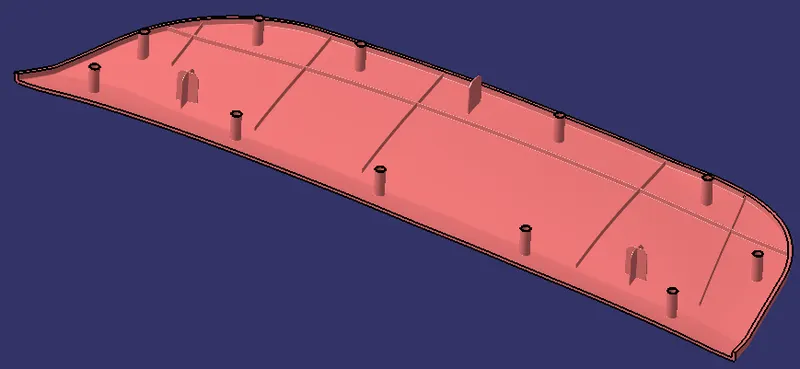
Heat stakes are used to join thermoplastic parts to another part of dissimilar material (metal/plastic). Heat Staking is an assembly method that uses a controlled melting and reforming of a plastic stud or boss to capture or lock another plastic or metal component of an assembly in place. The stud usually protudes through a hole in the component to be locked in place. The heated thermal tip contacts the top of the stud which melts and fills the volume of the tip cavity to produce a head, locking the component in place.
- Outer Diameter- 7mm
- Inner Diameter- 5mm
- Draft Angle- 0.5° internal and external
- Height- Depending on the extension required abover the mating part. Less than locators height.
The heat stakes created are translated to different locations using the points created using the "point and planes repetition" option.
11. Mating Part
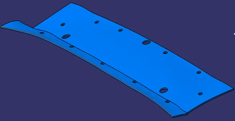
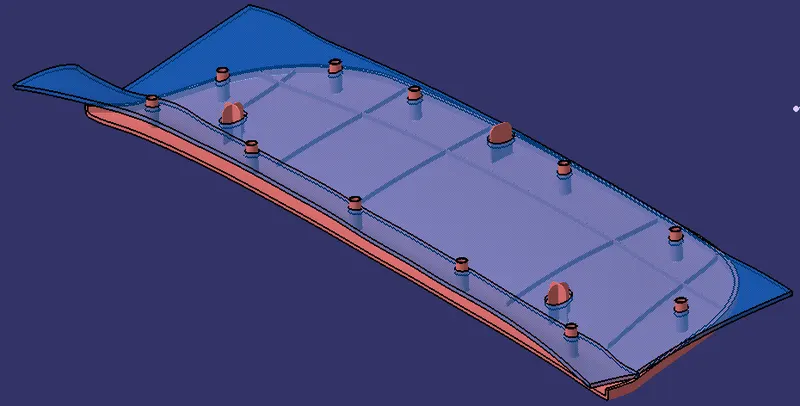
Holes are created on the mating to allow the locators and the heat stakes to pass through it. Usually a clearance of 0.1 mm is provided for locators and 0.5 mm for heat stakes. Sufficient length to be provided for the locators and heat stakes to allow them to pass through the mating part.
Mating part- Door Side Trim
12. Draft Analysis
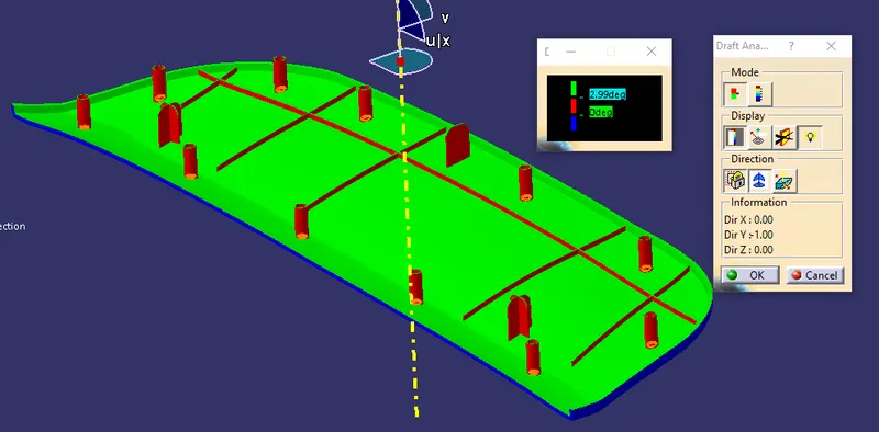
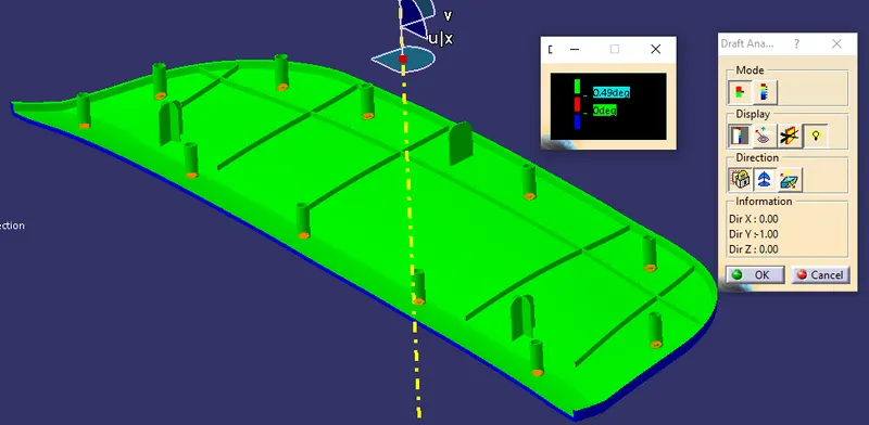
Draft Analysis was performed for the door applique plastic part. From the result, it can be understood that the part is manufacturable along the tooling axis.
3 degrees for the part
0.5 degrees for the features
Views
Appendix