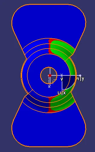
Week 8 - Challenge 1 - Draft Analysis on a Fan Cover
DRAFT ANALYSIS PROCEDURE
Draft Analysis reduces the tedious manual verification of the draft angles across various locations in a part.
1. TOOLING AXIS CREATION
Step 1- Analyse the component clearing in all 3 directions and decide the best tooling direction manually and create a dummy tooling axis.
Step 2- Create cut sections of the component along xz and yz planes.
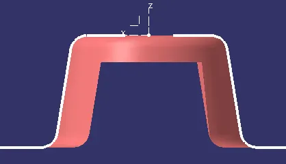
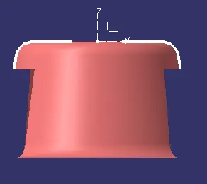
XZ Plane YZ Plane
Step 3- Create the Tooling Axis along xz and yz planes by creating a bisecting line from the draft lines obtained from the cut-sections obtained in step 2 respectively.
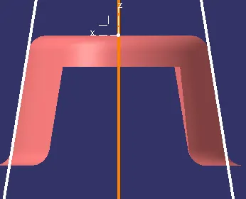
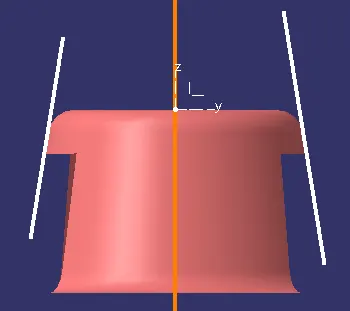
XZ Plane YZ Plane
Procedure-
1. Use Intersect option to create the section curves along XZ and YZ planes as shown in the above pics.
2. Create lines matching the doubtful part of the curve. In the aboves pictures, the slanting lines on either sides of the center are to be verified for part clearance. Hence lines are drawn matching them as shown in step 3.
3. Bisecting option is used to create the tooling axis X and Y directions.
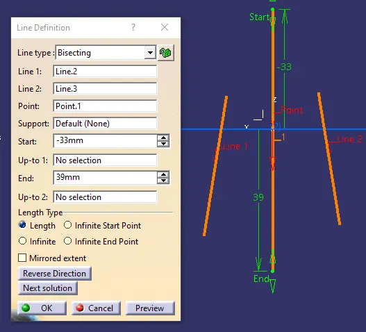
STEP 4- Create a bisecting line for tooling axes along xz and yz planes which is the actual tooling direction.
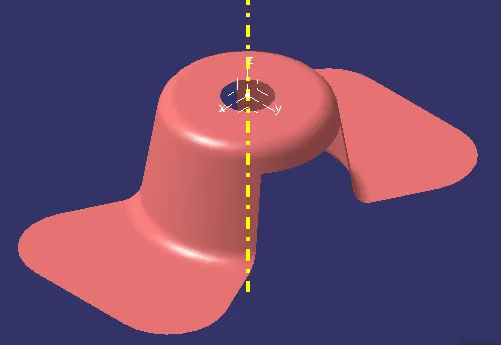
Tooling Axis
STEP 5- The tooling Axis and the class A surface are published to use for draft analysis.
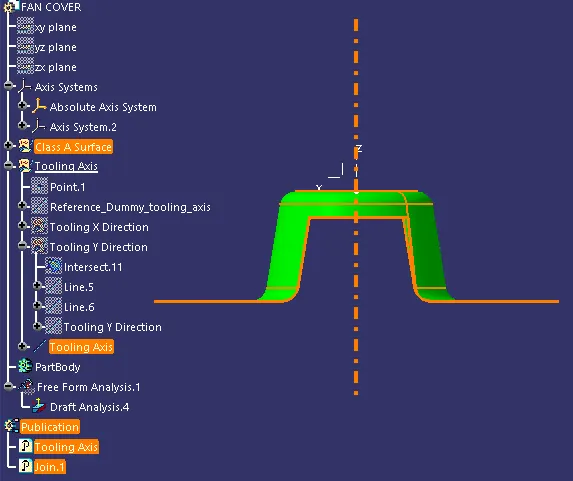
2. DRAFT ANALYSIS
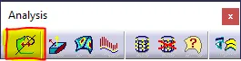
STEP 1- Choose the Feature Draft Analysis command from the Analysis toolbar marked in red box.
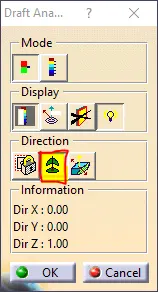
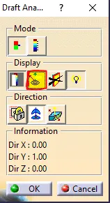
STEP 2- Enable the compass feature in the Draft Analysis Toolbar as shown below.
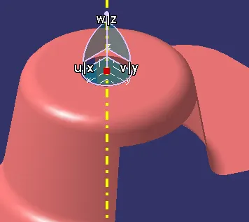
STEP 3- Place the compass on the required position and along the desired tooling direction on the part.
STEP 3- Select the part on which draft analysis has to be performed. The part turns to the combination of colors present in the scale.
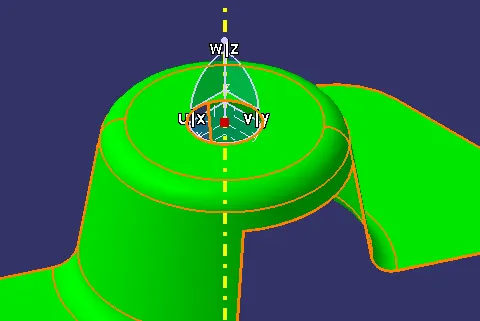
STEP 4- Analyse the part w.r.t the results obtained based on the scale, to identify the parts with draft feature. Quick analysis mode was chosen for the analysis.
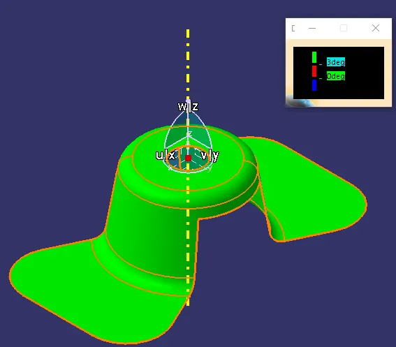
Since the required draft value is 3 degrees as seen in the scale, the parts highlighted in green color have draft values greater than 3 degrees i.e, the parts achieved required draft value and the part can be cleared.
The values at different locations can be probed using analyses under the running point option in the analysis tab as marked below. The picture on the right shows the value of the draft angle on a particular spot on the side of the part.
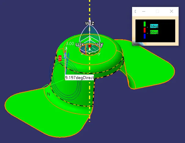
Thus the draft angles are verified using draft anlalysis. Also full analysis mode can be run for a part with multiple draft features at different draft angles.
For understanding, i have set the clearing axes along X and Y directions and the results are as follows where red color indicates that the draft value is between 0 and 3 degrees, and blue indicates that the value is below 0 degree called undercuts in industrial terms.
Tooling Axis X direction
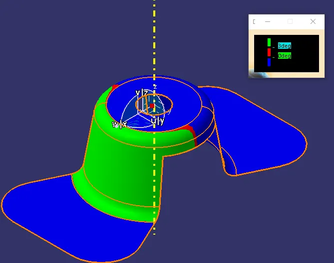
Tooling Axis Y direction
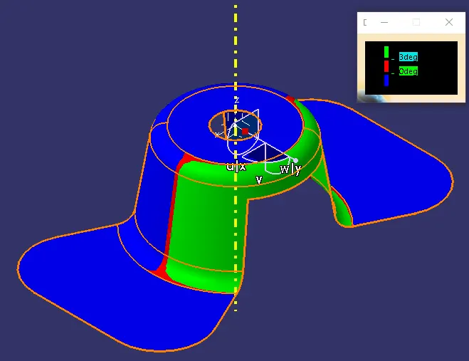
VIEWS (TOoling Y Direction)
Iso
Side
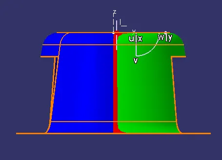
Front
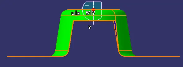
Top