Week 8 - Challenge 2 - Base Bracket Design
AIM:
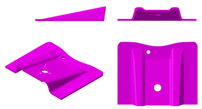
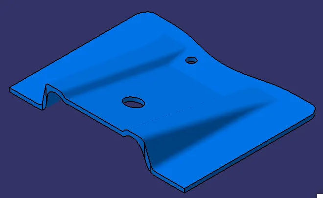
The purpose is to develop a manufacturable solid CAD model from the given class A surface of the base bracket.
PROCEDURE:
1. Deciding the Tooling Axis
- The model is observed in all 3 directions to decide the best tooling axis direction in order to manufacture the part at a cheaper cost.
- Usually the holes or the flat surfaces are of primary concern to decide the tooling axis. The tooling axis is chosen in such a way that the above mentioned features are along its direction.
The base bracket has 2 holes and a flat base surface on and parallel to XY plane. Hence the component can be tooled along Z-direction.
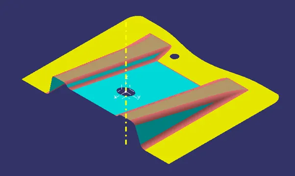
2. Tooling Axis Creation
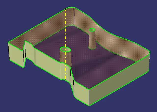
- After deciding the tooling direction, a point and an axis system is created at the center of the hole as shown in the picture above.
- A dummy tooling axis is created at the point placed at the hole center as mentioned in the previous step.
- Intersection command (Wireframe > Intersection) is used to create a cut-section of the component w.r.t. ZY plane of the axis system created as shown below.
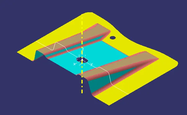
- The doubtful feature (usually drafted sides) of the component is chosen and analysed.
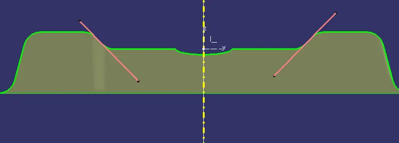
- Lines are drawn matching the angular lines present in the cut-section of the part created in step 3.
- A bisecting line is created w.r.t. the lines created above.
- Since the given component has drafts along ZY plane, the final tooling axis is created based on the angular lines from ZY cut-section only.
3. Draft Analysis
- Draft Analysis is performed to analyze if the component is toolable along the tooling axis.
- Feature Draft Analysis (Analysis> Feature Draft Analysis) option is used to perform draft analysis on the component.
- The compass is placed on the created tooling axis using the option in the Draft Analysis tab as shown below.
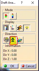
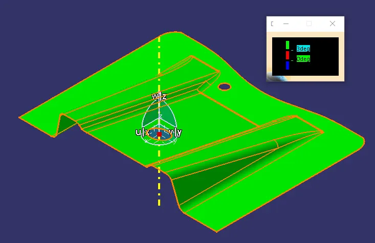
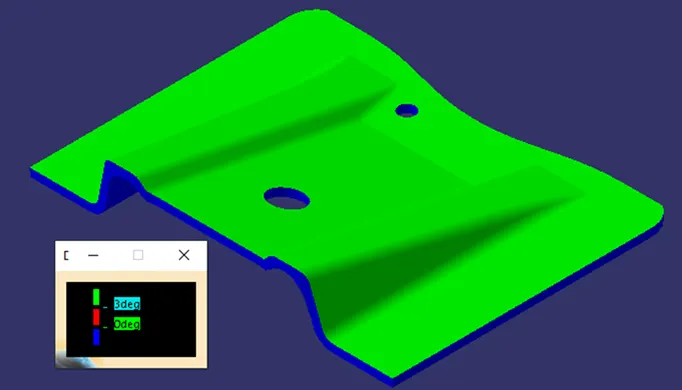
- Next the component is chosen to perform the draft analysis. The maximum draft angle is chosen to be 3 degrees (standard value).
- The parts highlighted in green have draft angles from 0 to 3 degrees.
4. Class A surface modification
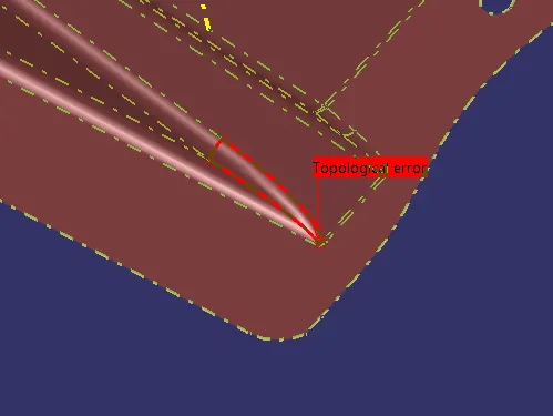
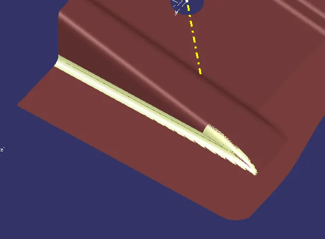
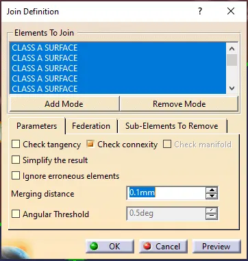
- Since the given class A surface couldn't be joined together with the default parameters in the join option, some of the features were recreated using symmetry option and joined together.
The merging distance was given as 0.1 mm so as to avoid the joining error.
5. B Surface Creation
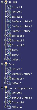
- The whole B surface was divided into 4 parts namely, Rib LH, Rib RH, Base and connecting surface as shown below.
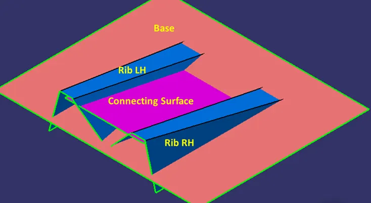
- Each surface extracted from the given class A surface is extrapolated and trimmed to obtain the final shape in the picture above.
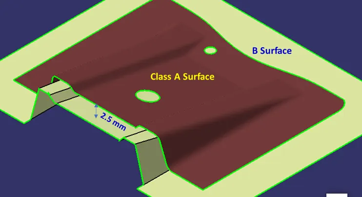
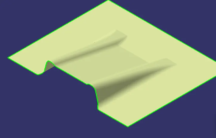
- These are then offset 2.5 mm from the class A surface, trimmed w.r.t each other and edge filleted to form the B surface (base of the actual component) as shown below. The radius of the fillets are 5.5 mm (3mm-Class A surface fillet radii +2.5 mm- part thickness) which are measured from the cut-sections created previously.
6. C Surface Creation
- Boundary of the class A surface is created as highlighted in green in the pic below.
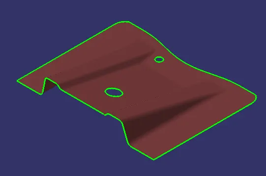
- Then this boundary is swept along the tooling axis direction.
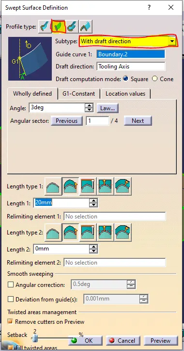
- The following sweep option was used.
- C surface w.r.t class A surface and B surface.
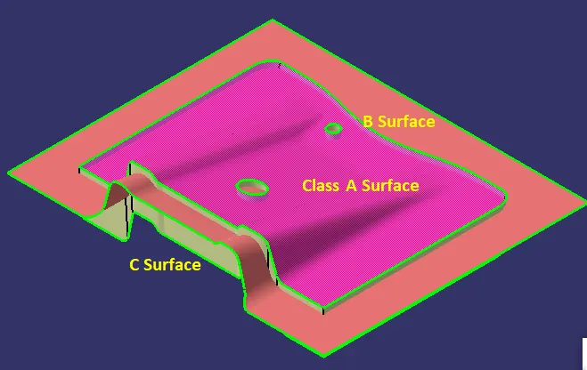
- Then these 3 surfaces were trimmed w.r.t. each other to form the final surface CAD model.
7. Part model creation
- With the surface model obtained in the previous step, the solid model is obtained by using closed surface option in the part workbench.
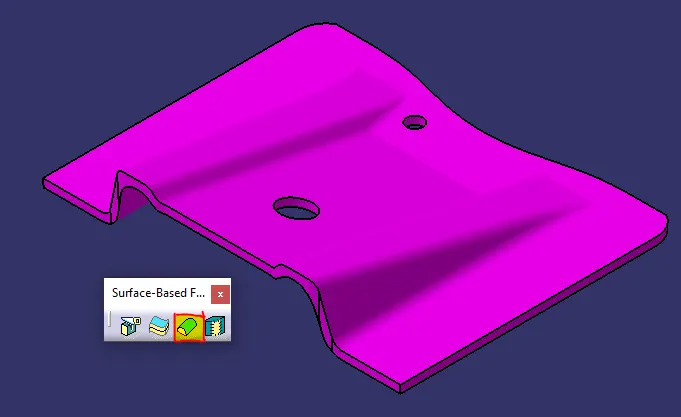
- Draft Analysis was performed for the solid part to check the manufacturing feasibility.
RESULT:
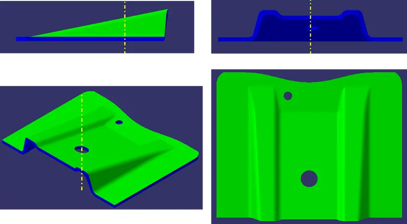
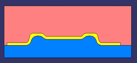
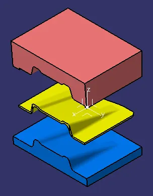
A solid model is obtained from the given class A surface which can futher be used to manufacture the component. The core, component and cavity will appear as in the following pictures.
Appendix:
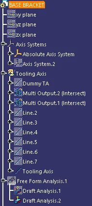
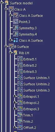
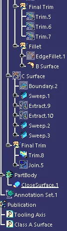
Tree Structure
Views