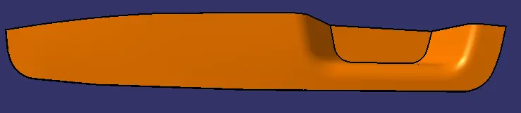
Week 8 - Challenge 5 - Core & Cavity Design
AIM:
The purpose is to design the core and cavity for a part designed from the given class A surface of an automotive switch bezel.
PROCEDURE:
- Deciding the Tooling Axis
- The model is observed in all 3 directions to decide the best tooling axis direction in order to manufacture the part at a cheaper cost.
- Usually the holes or the flat surfaces are of primary concern to decide the tooling axis. The tooling axis is chosen in such a way that the above mentioned features are along its direction.
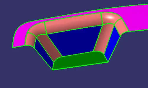
The switch bezel has 2 drafted walls along zy plane and 1 drafted wall along zx plane as highlighted in blue in the following picture. Hence the tooling axis has to be created in a way that the these walls are toolable.
- Tooling Axis Creation
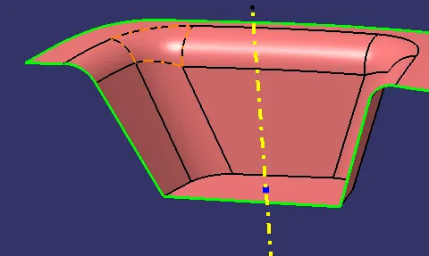
- After roughly deciding the tooling direction, a point is created at the center of the bottom flat surface as shown in the picture below.
- Intersection command (Wireframe > Intersection) is used to create a cut-section of the component w.r.t. ZY plane of the axis system created as shown below.
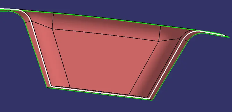
- Lines are drawn matching the angular lines present in the cut-section of the part created in step 3.
- A bisecting line is created w.r.t. the lines created above which is the tooling axis along ZY plane
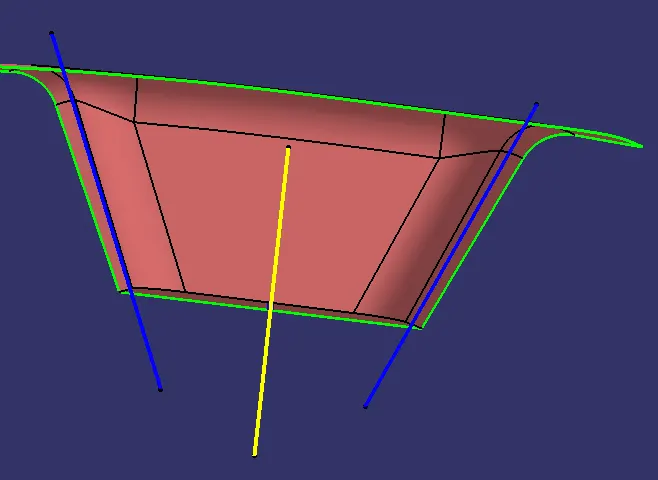
- Since there is only a single drafted wall along ZX plane, a line is created at an angle 6 deg w.r.t to the drafted wall. The reason is that while performing draft analysis on class A surface, the draft angle was above 3 degrees only when the ZX tooling axis is above 5 degrees w.r.t the blue line as shown below.
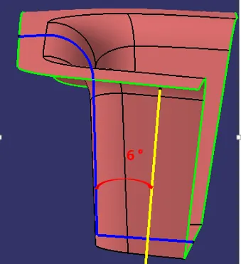
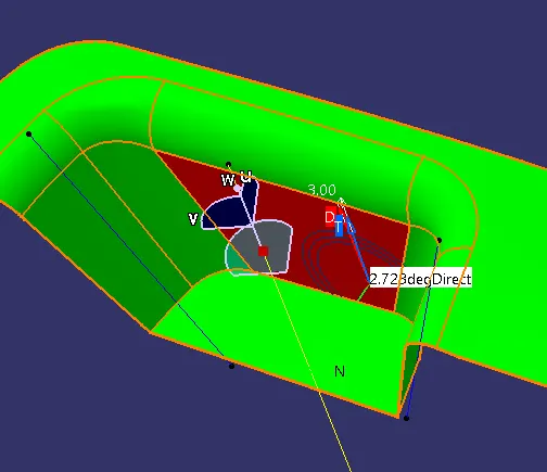
However, C surface couldn't be created with 5 degrees for the ZX tooling axis. Hence 6 degrees was chosen which satisfied both draft analysis and C surface creation. The following pictures show draft angle for 4 degrees, 5 degrees and 6 degrees of ZX tooling axis w.r.t the drafted surface along ZX plane (highlighted in red).
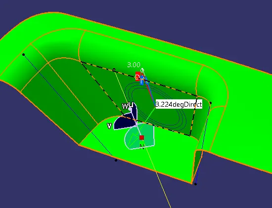
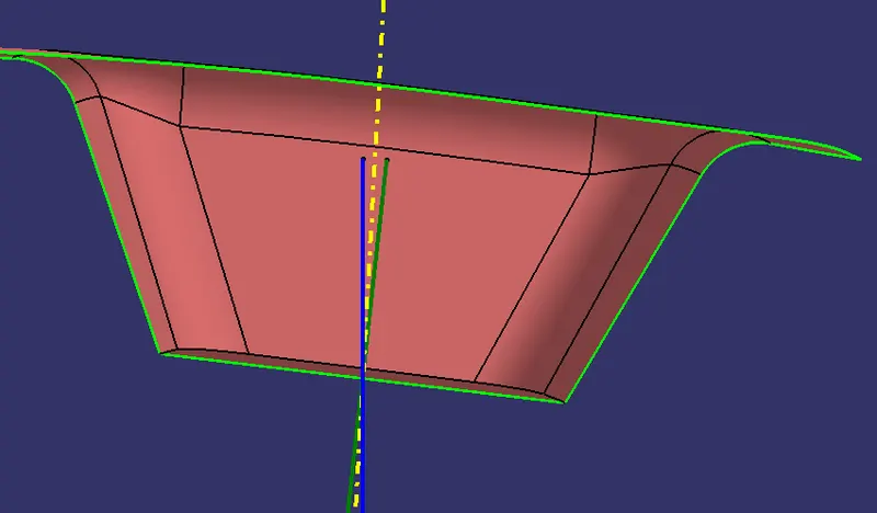
- Since the given component has drafted walls along ZX and ZY plane, the final tooling axis (dashed yellow line) is created by bisecting the tooling axes created in the along ZX (blue) and Zy plane (green).
- Draft Analysis
- Draft Analysis is performed to analyze if the component is toolable along the tooling axis.
- Feature Draft Analysis (Analysis> Feature Draft Analysis) option is used to perform draft analysis on the component.
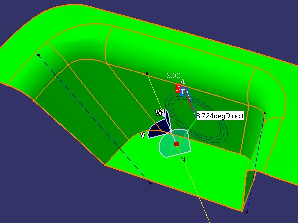
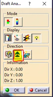
- The compass is placed on the created tooling axis using the option in the Draft Analysis tab as shown below.
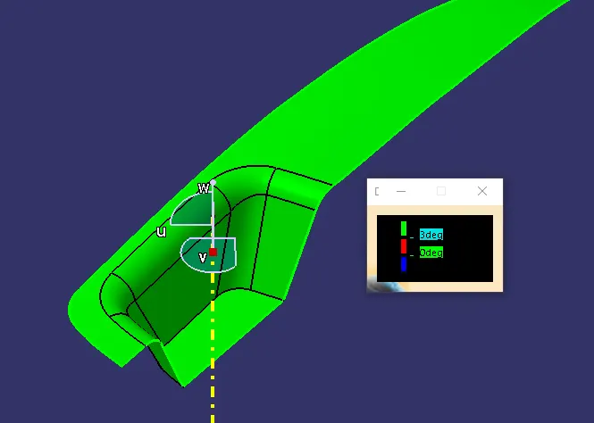
- Next the component is chosen to perform the draft analysis. The maximum draft angle is chosen to be 3 degrees (standard value).
- The parts highlighted in green have draft angles from 0 to 3 degrees.
- Class A surface modification
- Since the given class A surface didn't form a single boundary with the default parameters in the join option, 0.002 mm merging distance was given as an input.
Since the maximum allowable merging distance is only 0.003mm, the merging distance was chosen to be 0.002 mm so as to avoid the joining error.
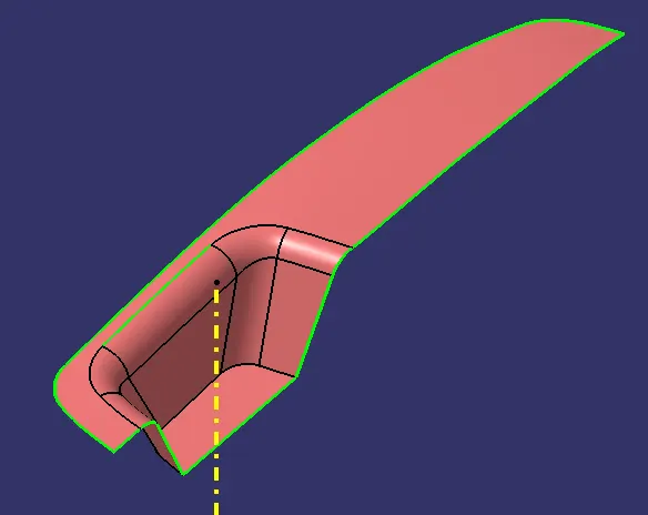
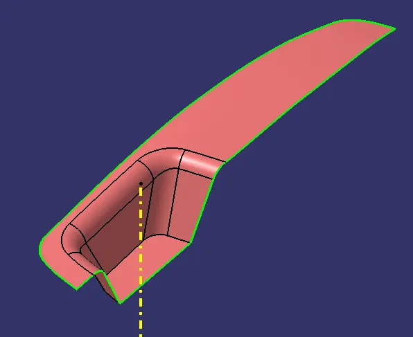
merging distance-0.001 mm 0.002 mm
- B Surface Creation
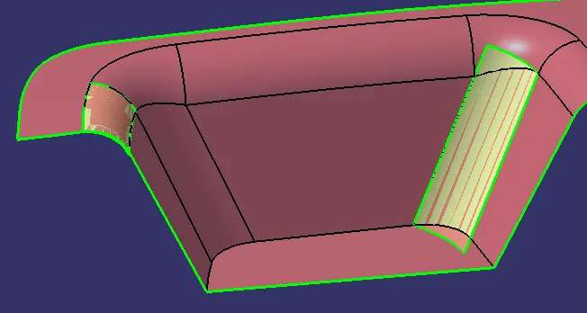
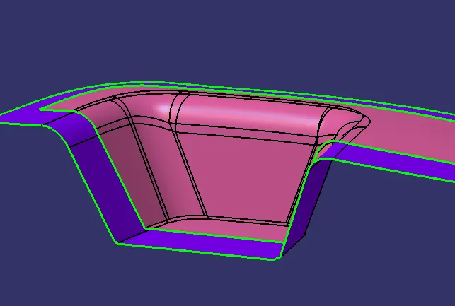
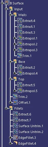
- The whole B surface was divided into 3 parts namely, Walls, base and top surfaces as shown below.
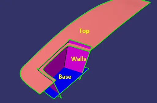
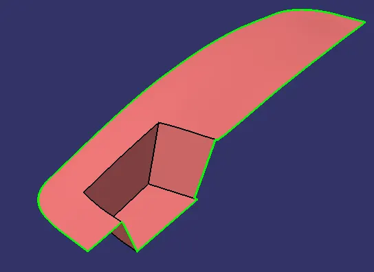
- Each surface extracted from the given class A surface is extrapolated and trimmed to obtain the final shape in the picture below.
- These are then offset 2.5 mm from the class A surface, trimmed w.r.t each other and edge filleted to form the B surface (base of the actual component) as shown below. The radius of the fillets are 16.5 mm on the top and 17.5 mm on the sides (Example: 14mm-Class A surface fillet radii +2.5 mm- part thickness) which are measured from the curves obtained by untrimming the extracted fillet surfaces in the given class A surface model.
- C Surface Creation
- Boundary of the class A surface is created as highlighted in green in the picture below.
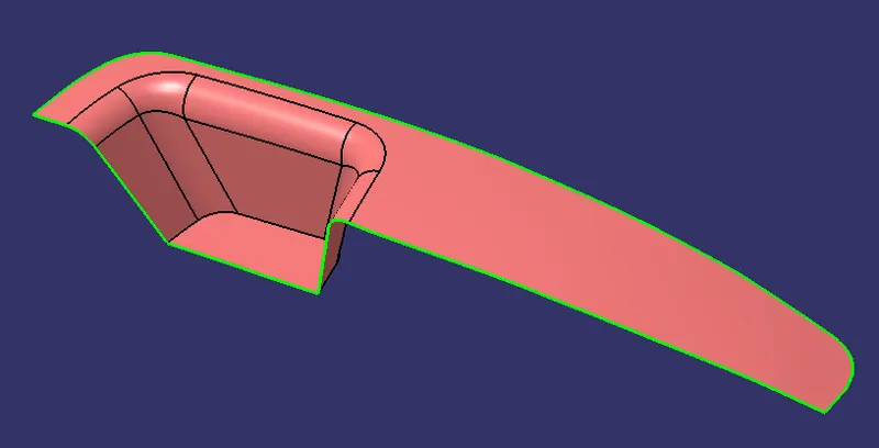
- The boundaries highlighted in green were extracted in 2 stages using multiple extract command and the curve is smoothened.
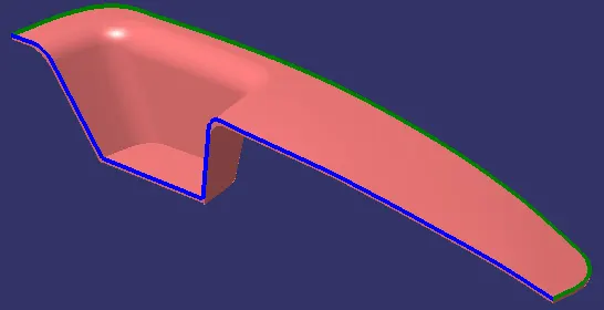
- Then the boundary was swept along the tooling axis. The following sweep option was used.
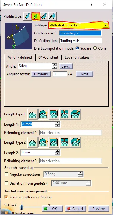
To form the flash along B surface which isn't visible to the user, the outward 3 degrees draft angle was chosen. This is the most preferred method.
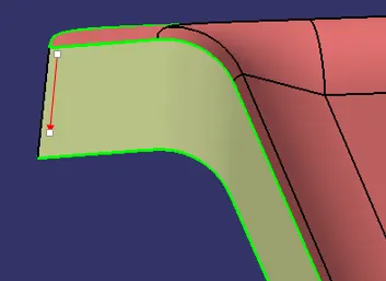
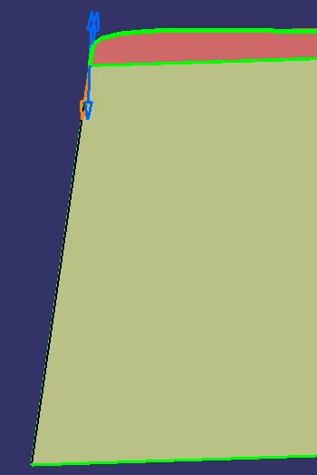
- To reduce the complexity, 2 boundaries as discussed previously were extracted and they resulted in the following profiles which were then extrapolated and trimmed to connect them together to avoid the gap as shown in the yellow box below.
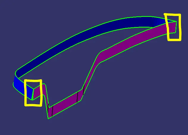
- C surface w.r.t class A surface and B surface.
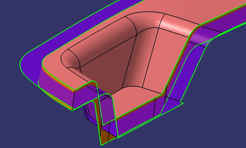
- Then these 3 surfaces were trimmed w.r.t. each other to form the final surface CAD model.
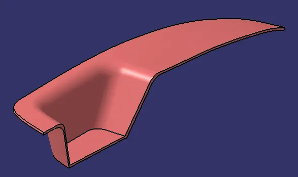
- Part model creation
- With the surface model obtained in the previous step, the solid model is obtained by using closed surface option in the part workbench.
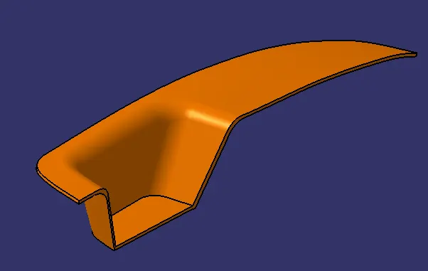
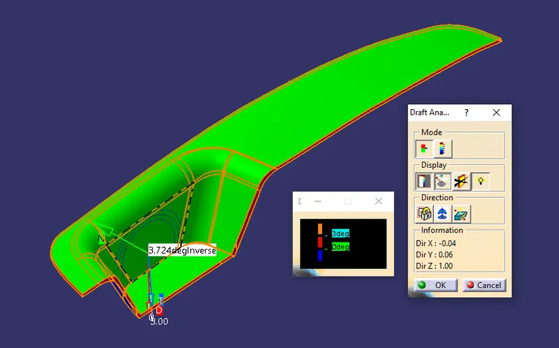
- Draft Analysis was performed for the solid part to check the manufacturing feasibility.
Views
Top
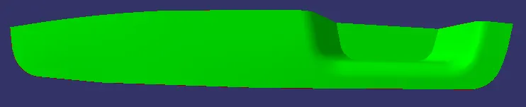
Side
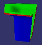
Front
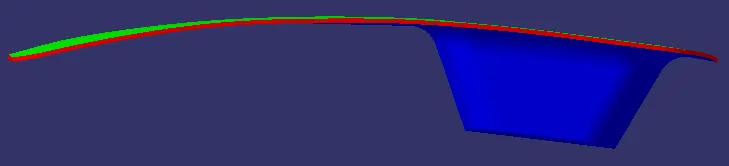
8. Parting Line and Parting Surface
Parting Surface- The parting surface defines the surface where the core and cavity separate.
Parting Line- It is the dividing line that splits the core and cavity halves of a molded part.
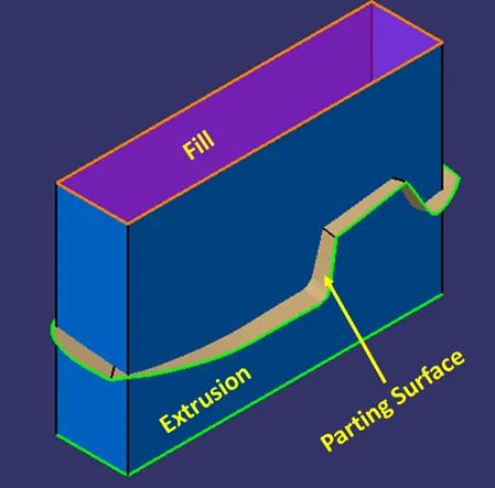
- The B surface created previously was extracted and extrapolated to form the parting surface. B surface is chosen because its always recommended to choose the parting surface on C and B surface intersection or on the C surface which is not visible directly to the users.
- Parting Line was created by extracting the boundary of the component along the parting surface.
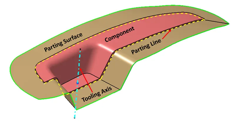
The above picture represents the parting line and surface.
9. Core
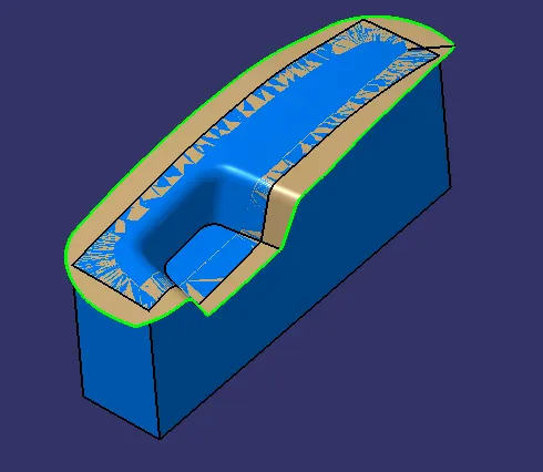
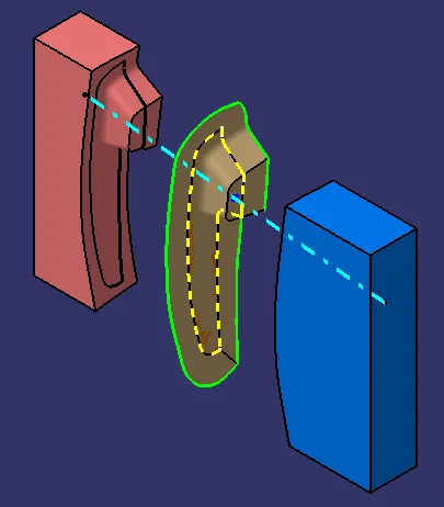
Core (male half) contains the projections that fills the cavity half of the mold. It has a convex surface. Usually it is the movable side of the mold. It is also referenced as A-side technically. The ejection system is attached to the core half of the mold in the injection machine. Once the part is cooled, usually it is stuck on the core while separated and then the ejector pin pushes the part sticking to the core.
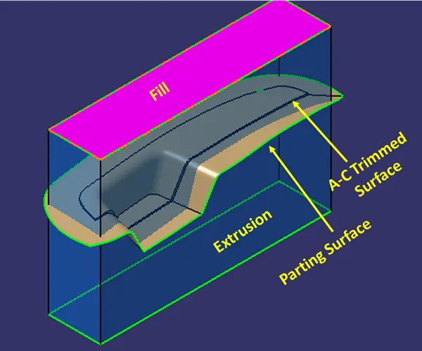
- Since the parting surface was chosen along the B surface, a rectangular surface was extruded to intersect the surface formed by trimming the parting surface, A and C surfaces.
- Then these 2 surfaces were again trimmed against each other and the open surface on the top was filled to form the core.
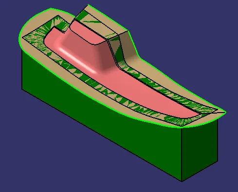
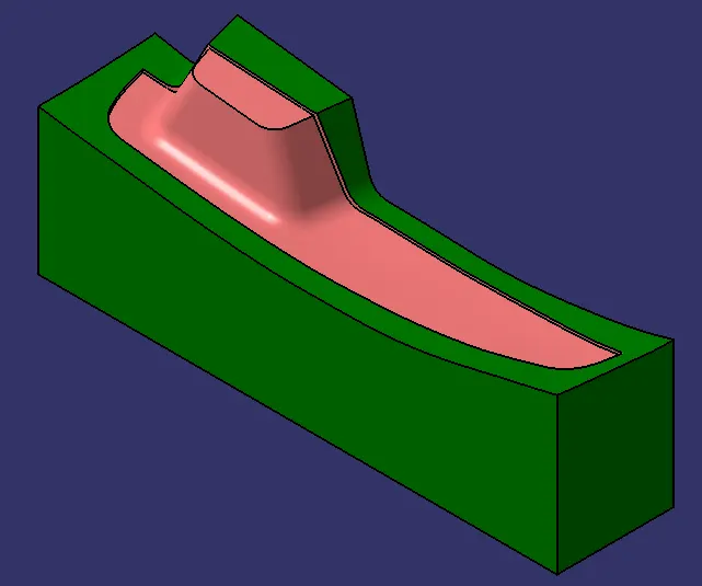
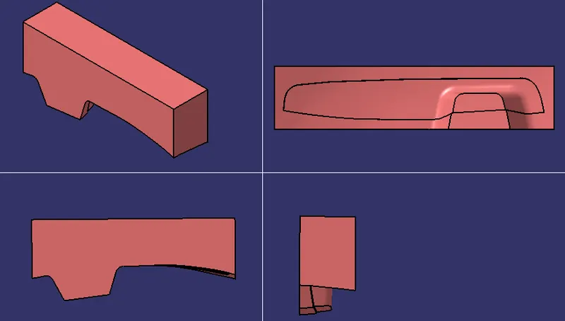
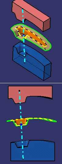
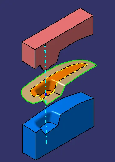
The core is shown in the above pic with the pink color representing the surface which meets the upper half of the part.
10. Cavity
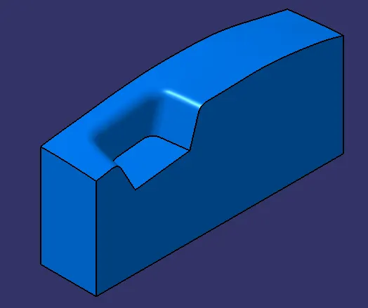
Cavity (female half) is the hollow half of the mold. It has a concave surface. Usually it is the fixed side of the mold. It is also referenced as A-side technically. The material is injected from the cavity side of the mold usually.
- Since the parting surface was chosen along the B surface, a rectangular surface was extruded to intersect the parting surface.
- These 2 surfaces were trimmed against each other and the open surface on the top was filled to form the cavity.
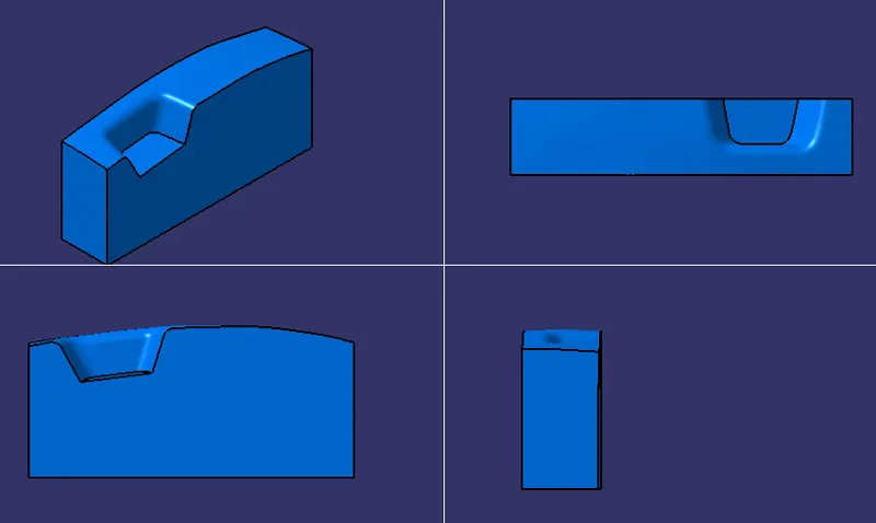
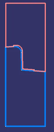
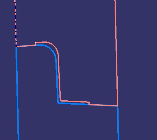
The following Figure shows the crossection formed by intersection of core, cavity and the component on the plane on which tooling Axis lies.
RESULT:
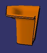
A solid model was obtained from the given class A surface whose manufacturing feasibility was verified through the draft analysis feature. Finally the core, cavity, parting line and parting surface were obtained based on the modelled part.
Appendix:
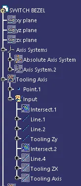
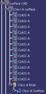
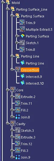
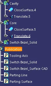
Tree Structure

Views
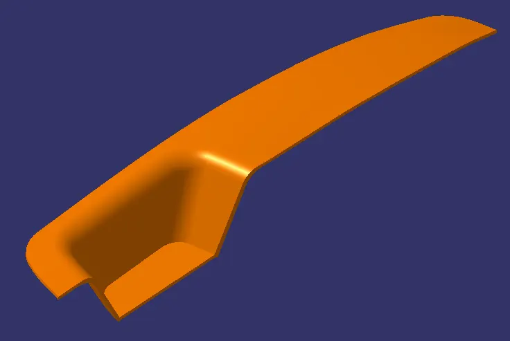
Isometric
Front
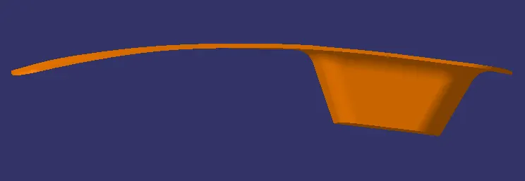
Side
Top