Week 9 - Attachment Feature Creation - Challenge 1
AIM:
The purpose is to model a toolable solid CAD model from the given class A surface of the Center Console Coin Holder and create engineering features like ribs on the B-Surface following the design rules.
PROCEDURE:
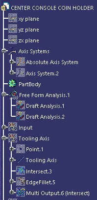
- Component Study and Tooling Axis Decision
- The model is observed in all 3 directions to decide the best tooling axis direction in order to manufacture the part at a cheaper cost.
- Usually the holes or the flat surfaces are of primary concern to decide the tooling axis. The tooling axis is chosen in such a way that the above mentioned features are along its direction.
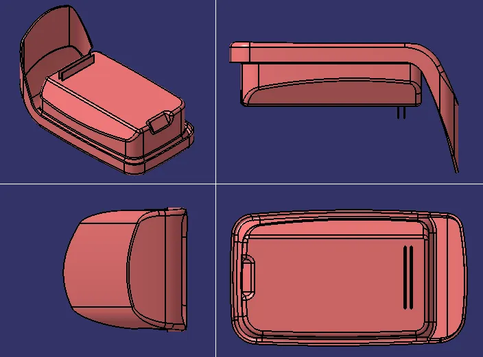
The given class A surface of the Coin Holder has 2 vertical walls along xy plane and zy planes respectively. Hence during part ejection, the mold is damaged due to the microgeometry undercuts restricting the motion of the part.
Drafts reduce the part travel against the mold. A feedback is usually provided to the respective class A Designer to provide draft angles on the walls.
Depending on the surface texture, draft angles are decided. However the nominal value is 3 degrees.
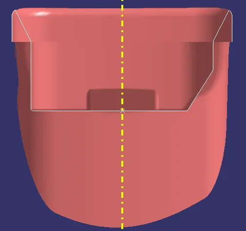
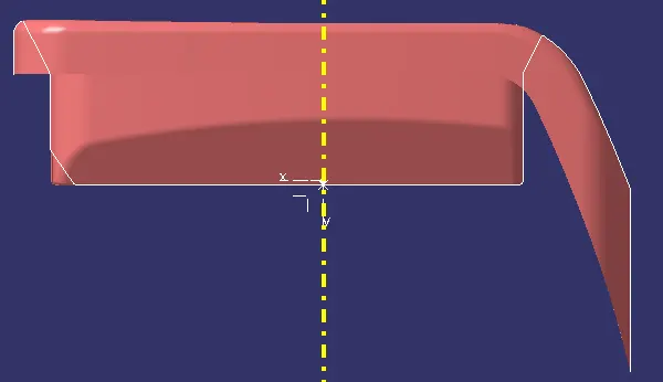
The above pictures show the part without draft angles on the side walls.
2. Tooling Axis Creation
- After roughly deciding the tooling direction, a point is created at the center of the bottom flat surface as shown in the picture below.
- Since there is no draft along the walls, the tooling axis is created perpendicular to the base on the point created in the previous step.
3. Draft Analysis
- Draft Analysis is performed to analyze if the component is toolable along the tooling axis.
- Feature Draft Analysis (Analysis> Feature Draft Analysis) option is used to perform draft analysis on the component.
- The compass is placed on the created tooling axis using the option in the Draft Analysis tab as shown below.
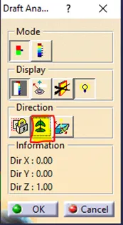
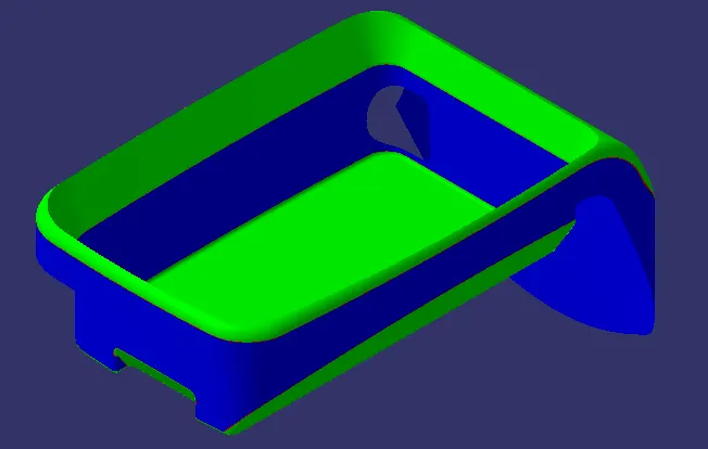
- Next the component is chosen to perform the draft analysis. The maximum draft angle is chosen to be 3 degrees (standard value).
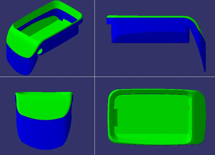
- The parts highlighted in green have draft angles from 0 to 3 degrees.
4. Class A surface modification
- Since the given class A surface didn't form a single boundary with the default parameters in the join option, 0.002 mm merging distance was given as an input.
Also the maximum allowable merging distance is only 0.003mm. Therefore, the merging distance was chosen to be 0.002 mm so as to avoid the joining error.
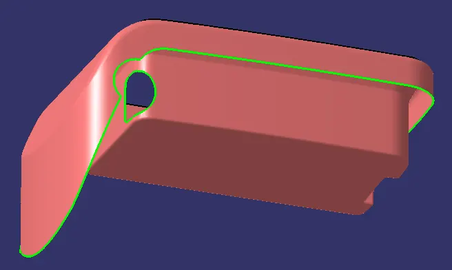
To verify that the class A surface is created as a single entity, the boundary is checked. The boundary of the surface in the above pic has 2 closed curves one for the part boundary and other for the hole.
5. B Surface Creation
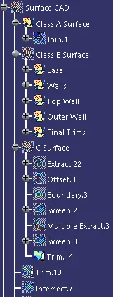
- Before creating the B surface, the model is studied to split the whole part into multiple parts for easier modelling. The whole B surface was divided into 5 parts namely, Side Walls, base, top wall, Outer Wall and Intersection wall as shown below.
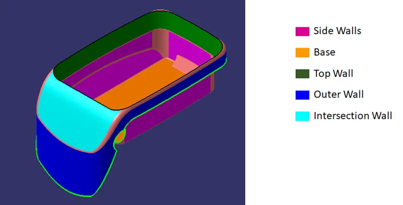
- Each surface present in each of the parts mentioned above was first extracted from the given class A surface.
- Then these are untrimmed and extrapolated to create an intersection between them.
- These are then offset 2.5 mm from the class A surface, trimmed w.r.t each other and edge filleted to form the B surface (base of the actual component) as shown below.
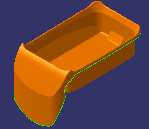
6. C Surface Creation
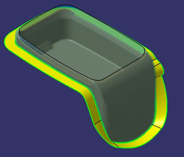
- Boundary of the class A surface is created as highlighted in green in the picture below.
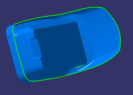
- The surfaces adjacent to the boundary were then extracted to use them for the sweep option in the next step.
- Then the boundary was swept perpendicular to the tooling axis. The following sweep option was used.
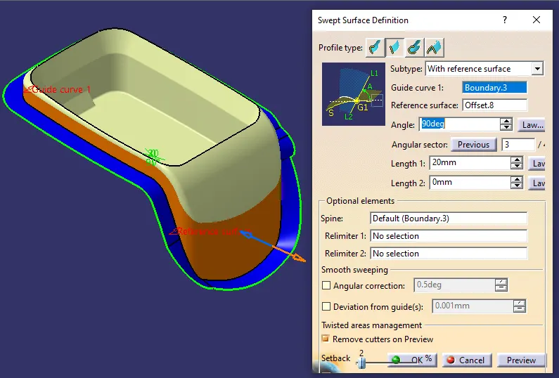
- The parts highlighted in orange are the adjacent surfaces and the C surface is highlighted in blue. Since the C surface is perpendicular to the tooling direction, it was swept for 90 degrees unlike the condition that the c surface is along the tooling direction where draft angle has to be considered.
- C surface w.r.t class A surface and B surface. The transparent surface
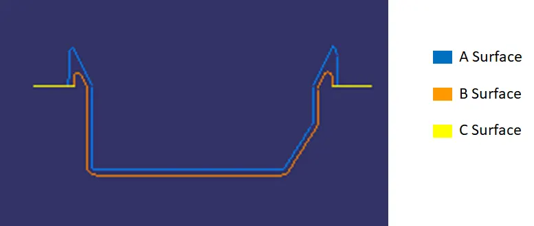
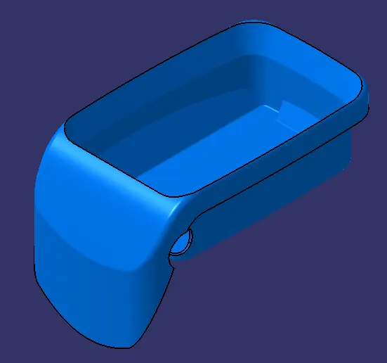
- Finally all 3 surfaces were trimmed against each other to form the final surface CAD model.
7. Part Model Creation
- With the surface model obtained in the previous step, the solid model is obtained by using closed surface option in the part workbench.
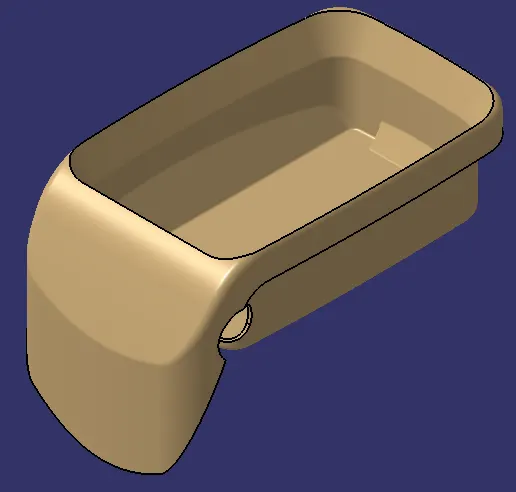
- Draft Analysis was performed for the solid part to check the manufacturing feasibility.
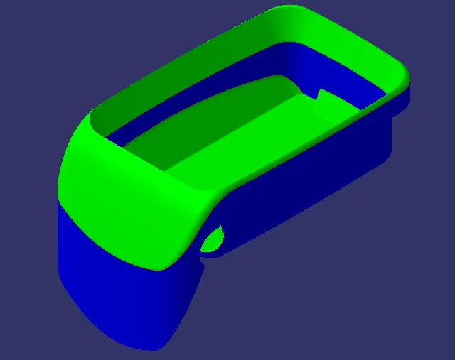
As discussed in the before, the surfaces highlighted in blue miss the draft angle. Hence these parts both damage themselves and also damage the mold. Hence care should be taken to provide draft angle.
8. Rib Modeling
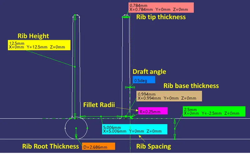
To prevent the plastic defects like sink marks from happening during the IM process, different sets of design rules are to be followed by the product designer namely-
- Minimum Rib Base Thickness- 0.4 x Part Thickness
- Minimum Draft Angle- 0.5° each side of the rib
- Maximum Rib Height- 5 x Part Thickness
- Minimum Rib Tip Thickness- 0.75 mm
- Fillet Radii- 0.25 Maximum
- Spacing between Ribs- (Maximum: Rib Height/2); ((Maximum: Rib Height/3)
- Rib root thickness- 1.3 x Part Thickness
The above set of rules are followed to create the ribs on the B-surface of the coin holder.
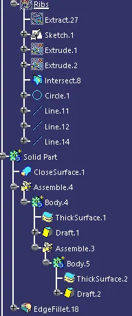
- A sketch was created initially on the extracted B-surface based on the design rules.
- Then a surface was extruded from the sketch along the tooling axis and thick surface option from the part workbench was used to create the solid ribs.
- The rib surfaces along the tooling direction were then drafted for 0.5°.
- Then these ribs were assembled to the main part through boolean operation to form the final part.
- Finally the surfaces of the ribs were filleted to arrive at the final design.
The following pictures show the ribs modeled and the dimensions of the several features on the part.
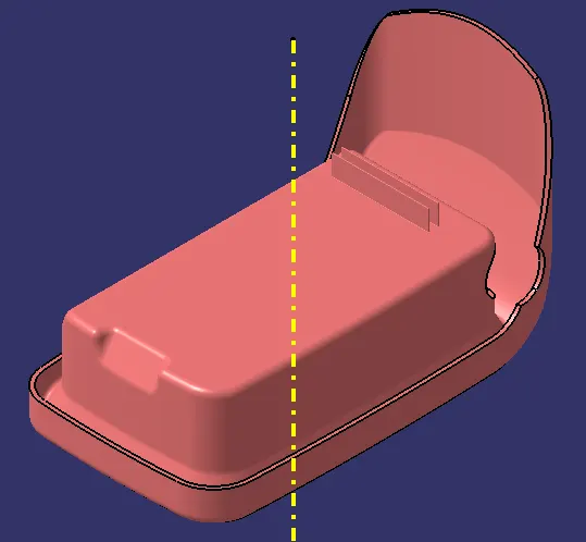
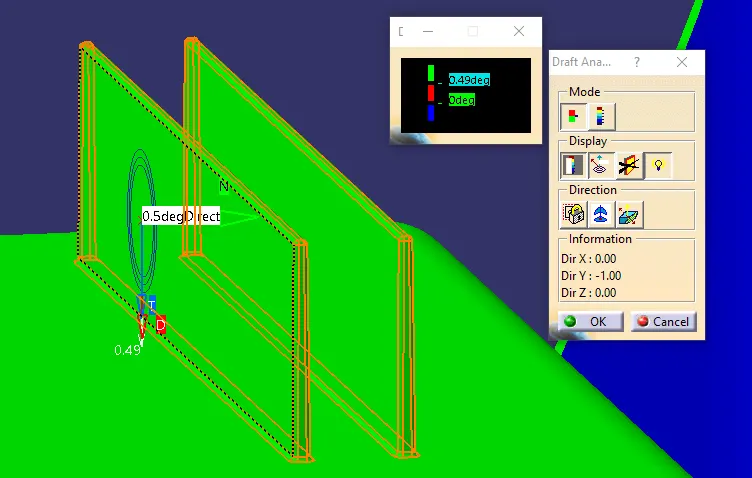
A draft analysis was performed to just check the draft angle which is shown below.
Views
Appendix