Week 9 - Project 1 - Door Applique Design with Engineering Features
AIM: To create the tooling axis meeting the requirements of the draft angle and perform the draft analysis Base Bracket Plastic component through the given Class-A surface. To create the Heat Stakes and the locators by following the design rules for the door applique.
Objective:
To define the locators and heat stakes and perform the draft analysis for the door applique.
Locators:
An essential concern in metalworking is locating the element to be machined, punched, bent, or stamped relative to the painting platform (fixture). As an example, a CNC machine device starts off evolving its process at a selected point relative to the fixture and proceeds from there. subsequently, the accuracy with which a component is machined is pretty dependent on the accuracy with which it's far positioned within the fixture. Accurate locating of not simply one component, but every and each element this is loaded into the fixture is vital. Any version in element location on the fixture provides the dimensional tolerance that has to be assigned to the completed elements.
Additionally, the method of helping and securing the component within the fixture affects now not handiest dimensional tolerances, however floor finishes as well. This is proper due to the fact incorrect supporting or clamping can temporarily or permanently deform the part. As a result, techniques for supporting and clamping need to be considered collectively with the technique of finding with a view to assure repeatability from element-to-part.
Finding of a element to be machined is a 3-step technique:
- Helping
- Locating (positioning)
- Holding (clamping)
The locating method: Degrees of Freedom
To specify the placement in area of a 3-dimensional object , the six coordinates are,
- Translational position along the X-axis
- Translational role alongside the Y-axis
- Translational position along the Z-axis
- Rotational function approximately the X-axis
- Rotational position about the Y-axis
- Rotational position about the Z-axis
- These six coordinates are referred to as the six tiers of freedom of a three-dimensional object. Because the double-headed arrows indicate, the translational and rotational positions can vary in both paths with respect to every of the three axes.
Heat Stakes: Heat Staking is a pulsed-heat process to join two or more parts out of which one at least is made of plastic. The process is to deform the plastic material using heat and force at a set process time. The bond is made by partially de-forming the plastic part in order to fix the other.
Tooling Axis :
The tooling axis is the method which decides whether the tool enters into mould or not as it denotes the draft clearance angle where a moulded part is easily removed from the mould.
Procedure for creating tool axis:
- Firstly, we will be given a class A surface which is looked as aesthetic and a smooth finish which is created with an Alias software workbench which is also known as a free imagination surface.
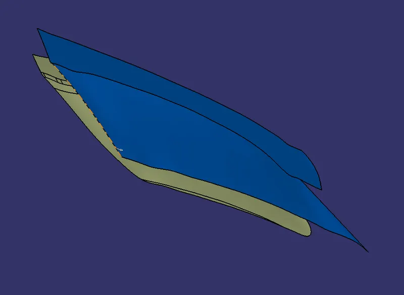
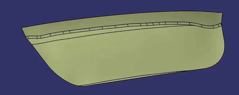
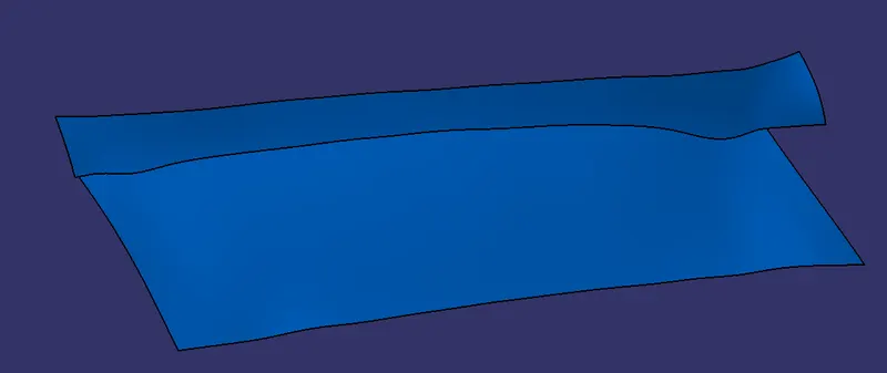
- For that class A surface, we need to check the boundaries first to check whether any unattached faces are present in that surface.Here there are two components which we have to find the draft analysis.
- We have to find the easy axis creation from that class-A surface and build the dummy tooling axis of X and Y direction and thereby creating the Tooling axis in Z direction.
- The below is the image of a class A surface which is given as an input.
- The primary motive of these locators and warmth stakes are that they'll act as fixtures among the 2 components.
- Insert the geometrical set and name it as locators. Create a point on the higher floor and create a plane parallel through that point inside the course parallel with the surface.
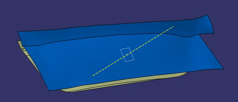
- Insert another geometrical set and name it as Tooling axis. Create a line via the created factor in Y-route and increase it sufficient.
- Below is the image of the tooling axis.
Procedure for Draft Analysis:
- Change the view mode to Customize View Parameters and select Material option from the Mesh. Next we need to get the compass and place it on the tooling axis.
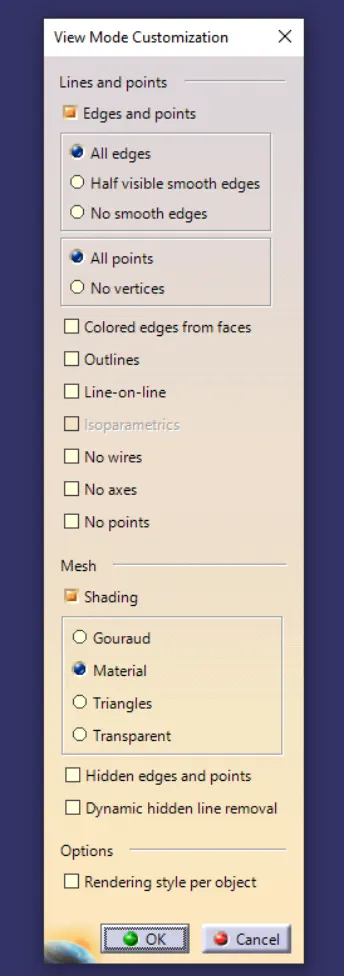
Click the Draft Analysis icon or choose the Insert > Analyze > Draft Analysis menu command.
- It is assumed that the mold will be pulled along the Z axis. You can change the Pull Direction in the Control Panel, or click and drag the Direction and Origin handles in the modeling views.
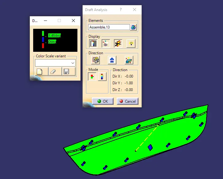
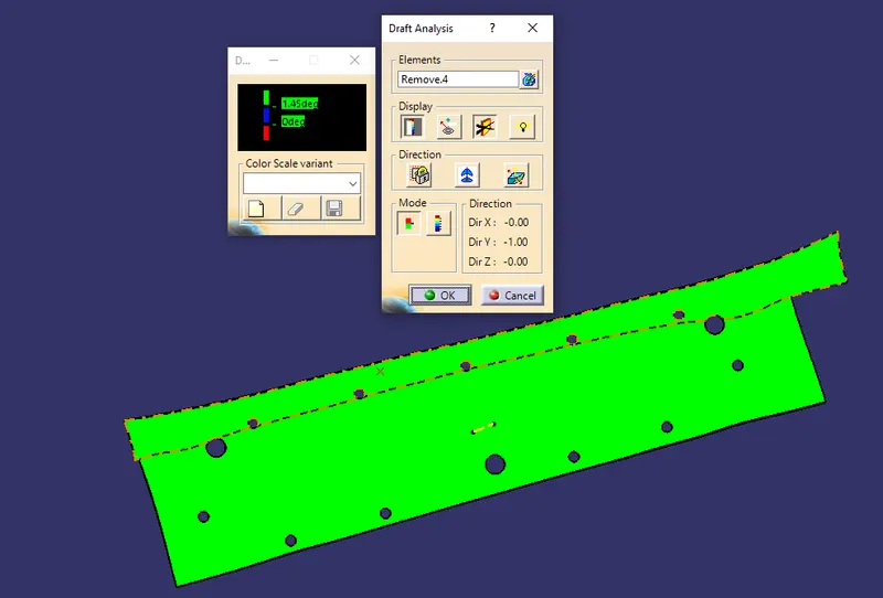
- Draft Analysis dialog box with colour scale (with quick analysis mode) appears on the screen. So the first mode option is the quick analysis mode and second is full analysis mode. Here the quick analysis mode is used.
- Change the value of green according to the draft angle provided to the part.
- To get a clear picture, either we need to adjust the compass by holding the marked region of the compass and dragging it towards the opposite direction or by selecting the inverse draft direction option inside the direction of Draft Analysis.
- After getting green colour on the component, try to adjust the compass using the knob, and adjust the direction of the compass to get green on the entire top panel region.
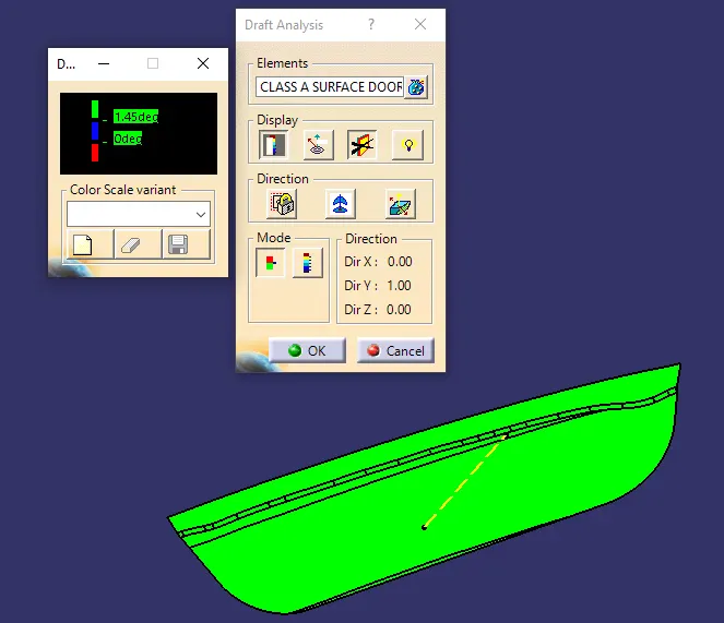
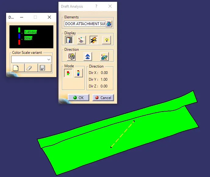
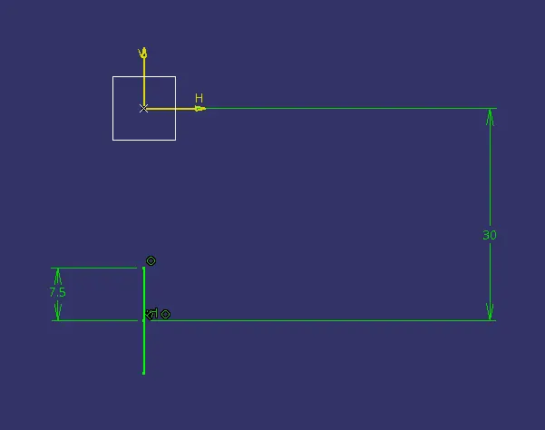
- Create a positioned sketch through the point created and the reference because the plane parallel through the point. Draw the 4 manner locator sketch with required dimensions. Make sure that the sketch is located at the appropriate region and is iso-constrained.
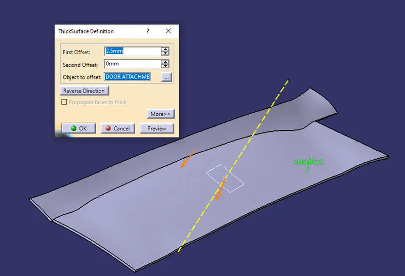
- Then switching to component part design, the part body is padded with thickening the two surfaces with 2.5mm as thickness. Thicken each of the surfaces in appropriate guidelines.
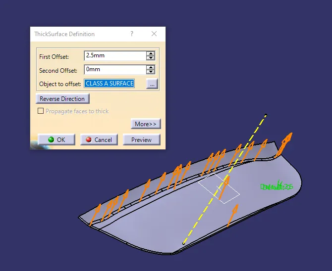
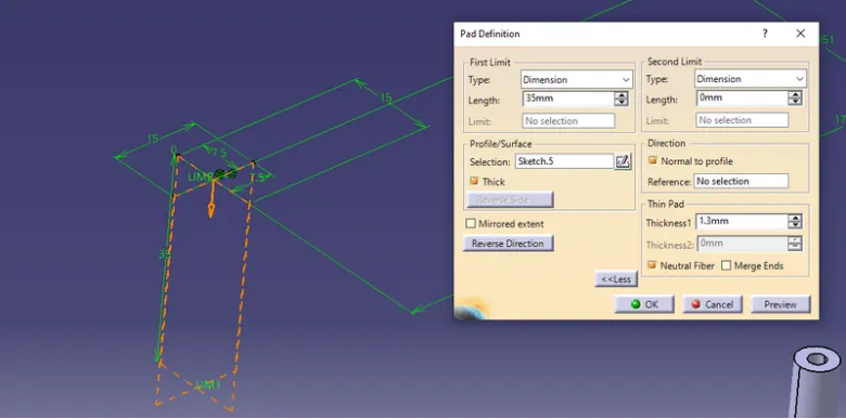
- The sketch which is drawn in the sketcher workbench is given pad with thickness 1.3 mm neutral fibre and extend in one limit. Insert a separate part body and rename it as 4 way locator 1 and define it as 4 way locator so that we can easily locate them while we search in the tree structure.
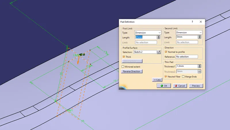
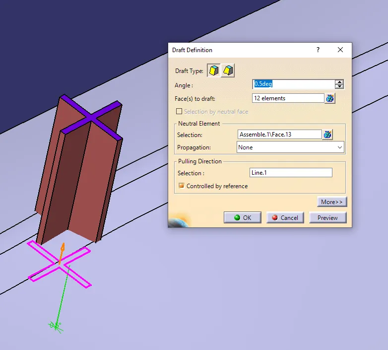
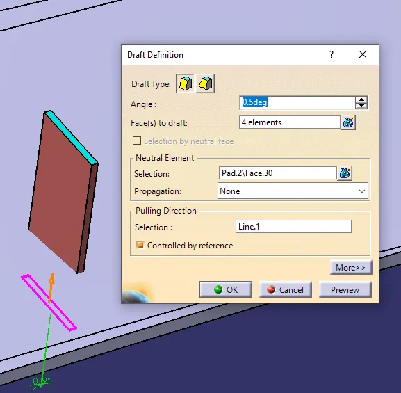
- Draft the faces of the locator with degrees and with specification of neutral element as the base of the locator , pick out the tooling axis as a pulling path.
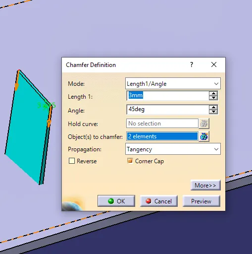
- Add the chamfers to the edges on top with 45 degrees as radius and 3mm length.
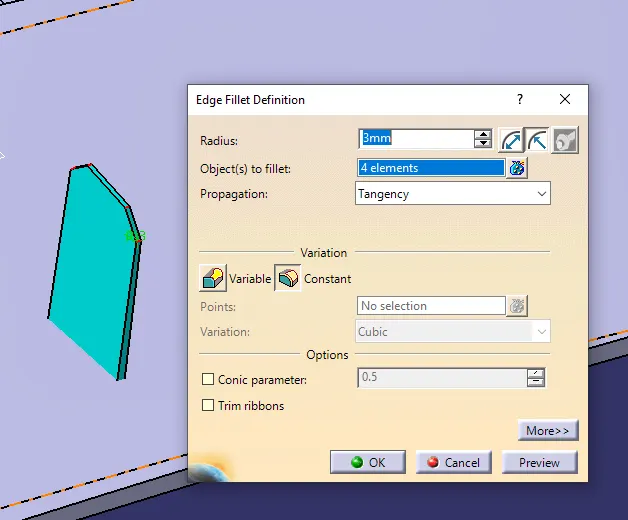
- Add the edge fillets to all the faces with 0.3mm as radius.
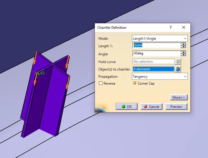
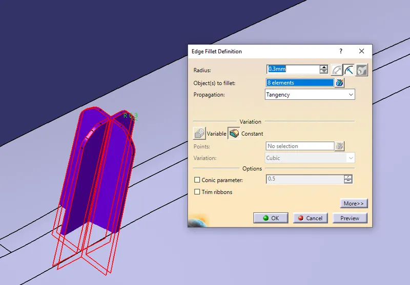
- To create another comparable four-manner locator in one of a kind area. Copy and paste the 4 way locator part body and with paste specials in the defined set. In the primary folder, use the translate command to replicate the identical body in a unique location and use coordinate system to translate. Make sure that the heights of the locators should be comparable from the attachment surface.
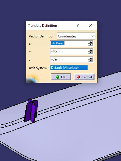
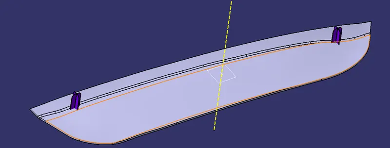
- Similarly, the sketch for the 2-way locator in between the 4-way locators to the similar height that of the 2-way locator and with 1.3mm thickness and neutral fibre option.
- Draft the aspect faces of the locator with 0.5 tiers and pick the bottom of the surface as neutral element and tooling axis as pulling direction.
- Upload the edge fillets and chamfer further that similarly as 4 way locators.
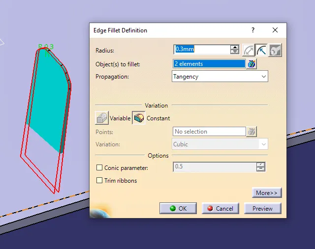
- Now using the Boolean operation which is the assemble operation. The 3 part bodies, the two 4 way locators and one 2 way locator to the main part body.
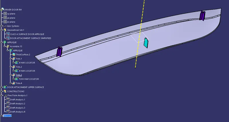
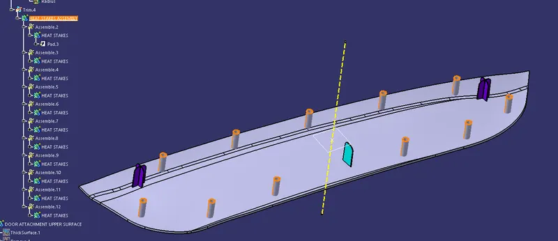
- Heat stakes are created on the barriers of the surface. Ensure that the heat stakes are a minimum of 50mm other than each other. Insert the geometrical set and name it as heat stakes and define it.
- Now unhide the higher surface and use the couple of extract choices to extract the boundaries using tangent propagation.
- Extract the floor of the attachment and off-set it to 2.5 mm upwards because the thickness of the element is 2.5mm.
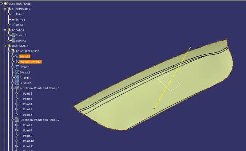
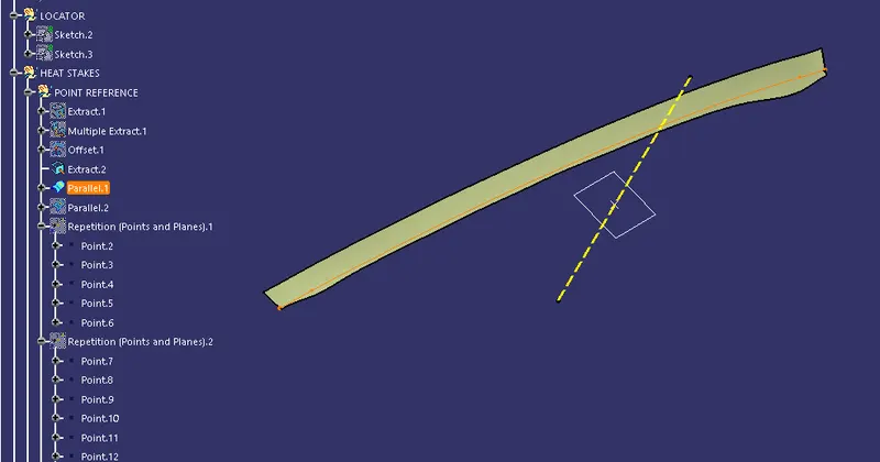
- The heat stakes are placed inside a positive distance away from the limits. Use the parallel curve option and 15mm distance to create obstacles and the off-set surface as base.
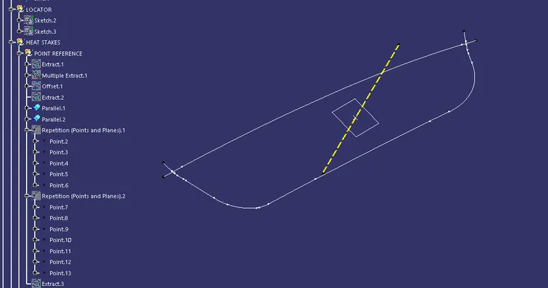
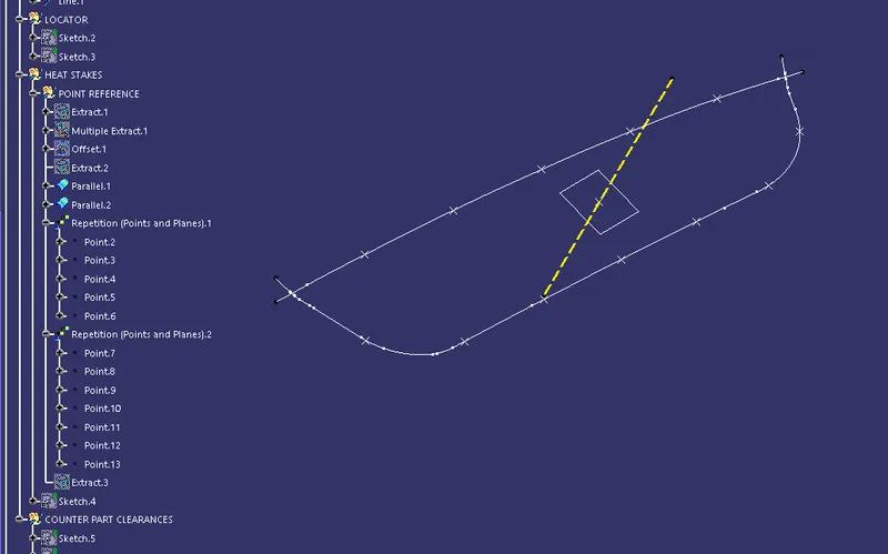
- Now the usage of the factors repetition option creates more than one point on the parallel curve. Unhide the strong body and make sure the heat stakes are not interfering with the locators.
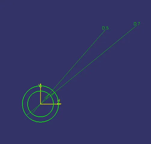
- Create a positioned sketch through the factors created on the parallel curve. The outer diameter should be 7mm and the inner diameter as 5mm.
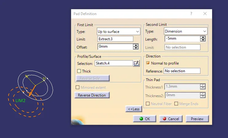
- Go out of the sketch and insert a component body and rename it as heat stakes and define it. The sketch should be padded with 1.3mm thickness and 35mm top with neutral detail option.
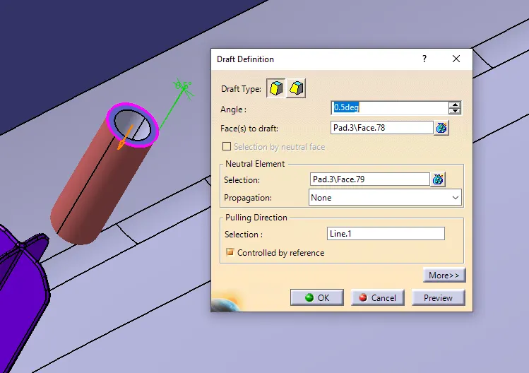
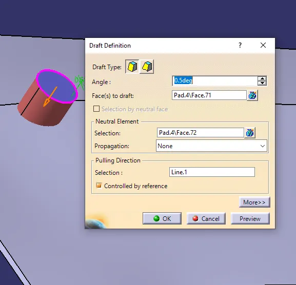
- Draft the faces of the heat stakes with zero.5 degree and neutral surfaces as the base and tooling axis as a pulling route.
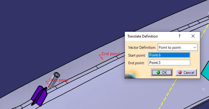
- Now copy- paste the unique heat stakes element frame to the primary folder and translate it to the other points at the parallel curve with point to point choice. Later by performing the identical procedure is to translate the other points at the parallel curve.
- Now the Boolean operation, the assembly operation uploads the element of our bodies of warmth stakes to the main part frame. Add the edge fillets with 0.3mm radius to all of the heat stakes created in the present part bodies.
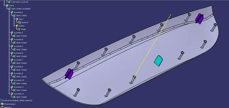
- The heat stakes and locators are created according to the design recommendations at the applique floor.
- Now the sketches of counter holes need to be created on the attachment surface.
- Insert a geometrical set and rename it as Counter holes and define it. We can create in specific approaches one via growing a placed comic strip via the reference factor from the previous cartoon or through going to element design and developing a circle via the points at the parallel curve. use the factor-radius alternative.
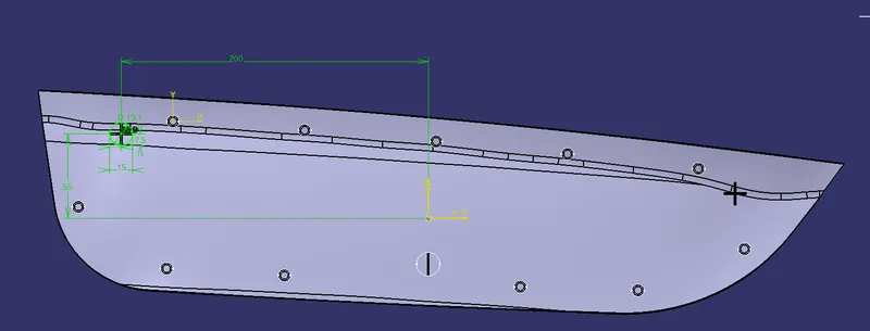
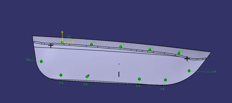
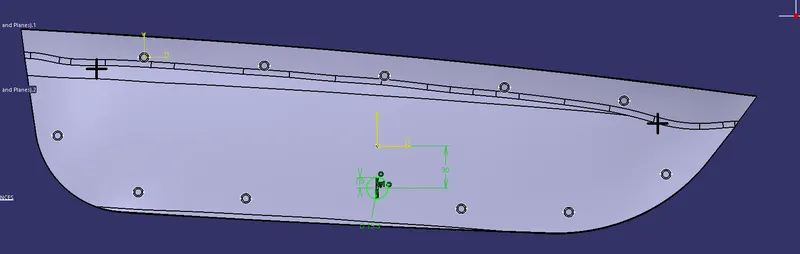
- Ensure that the clearance between the floor and the features created is at least 0.5mm. Therefore boom the diameter of the circle by 0.5mm.
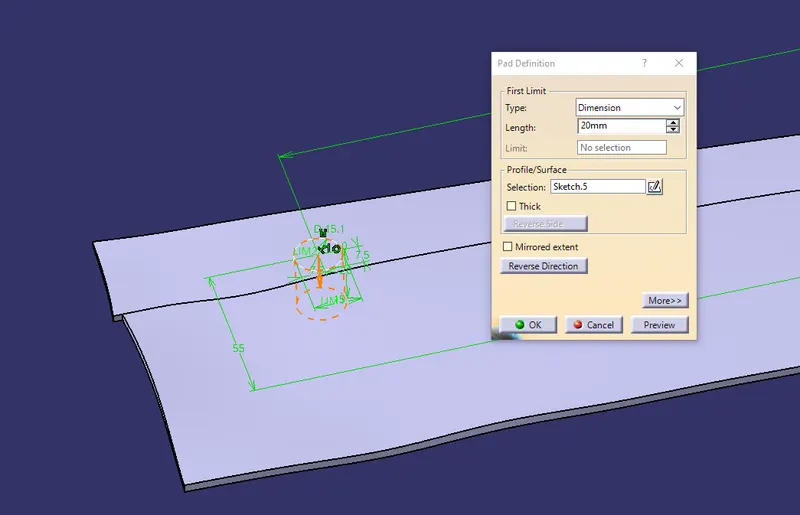
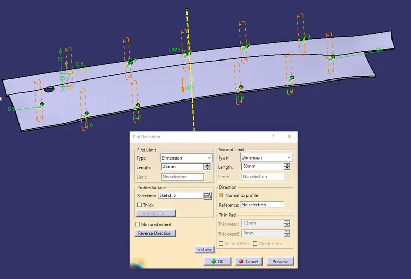
- Now extrude the circle to positive height and define the attachment solid component and via part body design. Split the extruded surface with the solid component to get a counter hole.
- Now Draft the counter component floor with 0.5 degree with the tooling axis.
- By using the measuring tool take a look at the clearance between the attachment floor and the locators and warmth stakes created on the attachment feature .
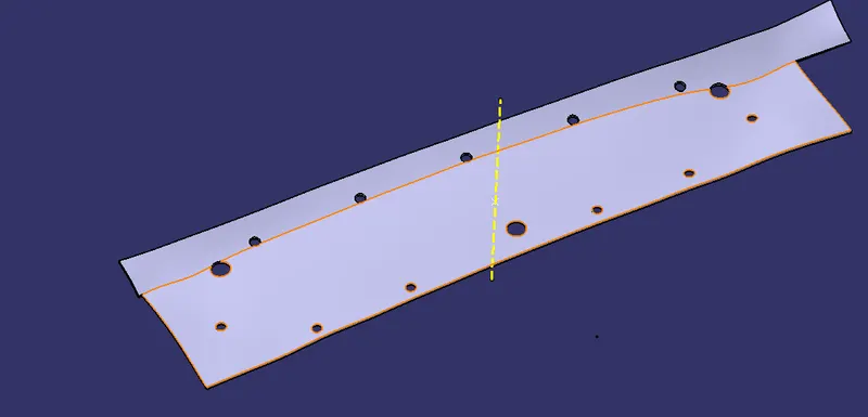
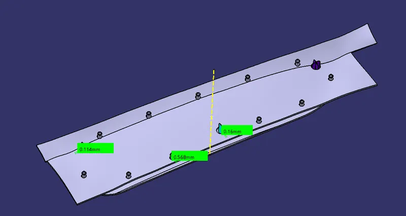
- The aim of creating locators and heat stakes on the applique part and clearing them through the attachment surface following the design rules.
- Now carry out the Draft analysis at the components. Goto Insert- evaluation - feature Draft evaluation. Pick the attachment floor and place the compass on the tooling axis. Look at the aspect visually.
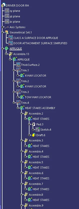
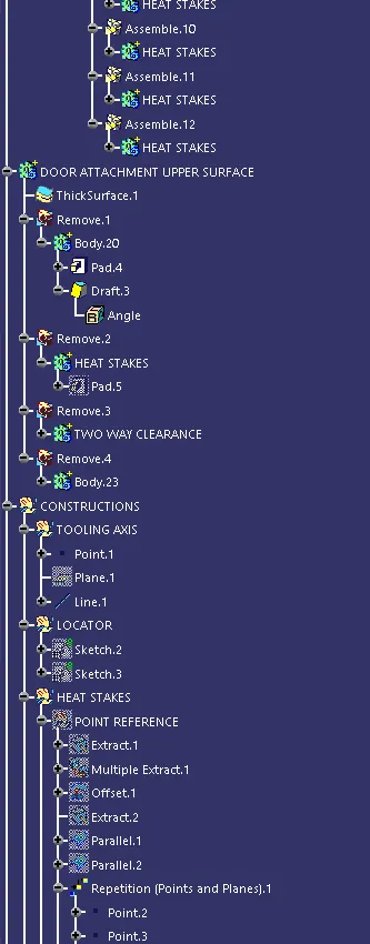
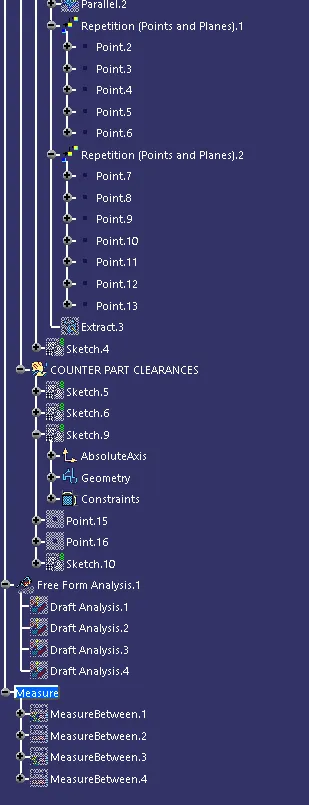
TREE STRUCTURE:
ISOMETRIC VIEW:
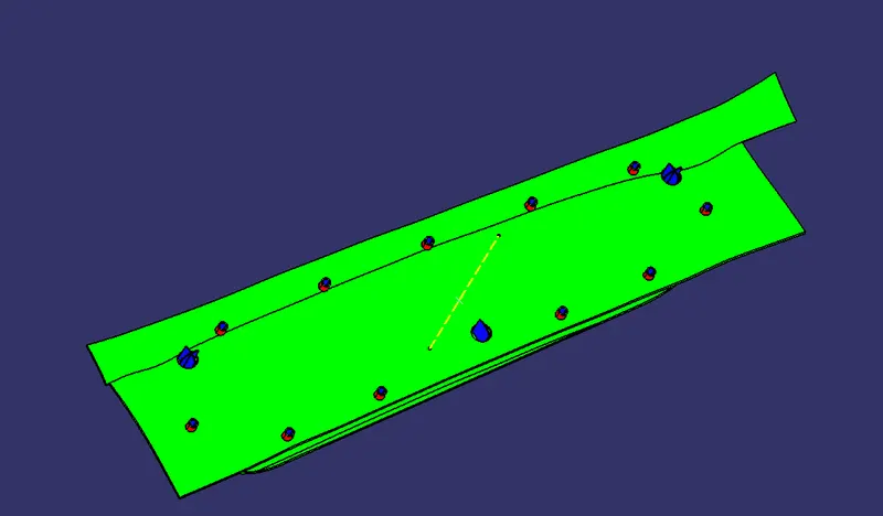
FRONT VIEW:
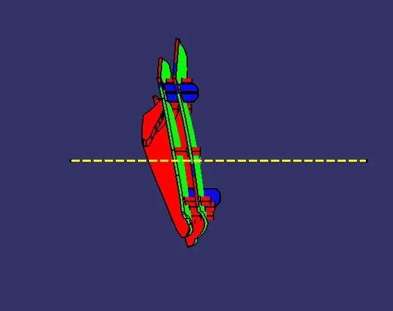
SIDE VIEW:
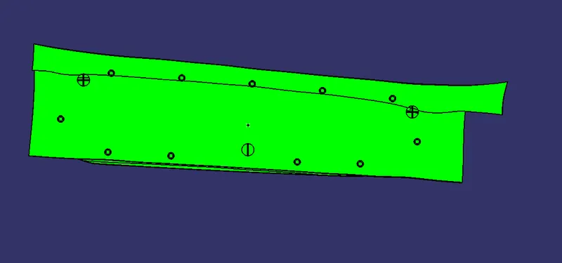
TOP VIEW:
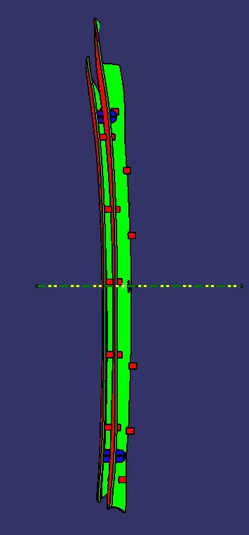
Conclusion:
- Succesfully created the Heat Stakes and the locators by following the design rules for the door applique.
GOOGLE DRIVE LINK: