Week 9 - Project 1 - Door Applique Design with Engineering Features
DOOR APPLIQUE
We have been provided with class A surface of Door Applique and we are converting it into solid part and B Side features like locators and heat staking.
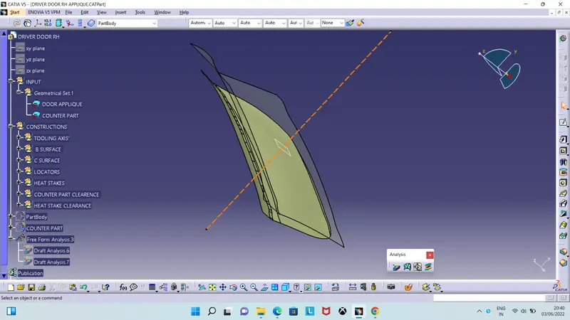
Fig: Class A Surface
Creating Tooling Axis
- Created tooling axis at the centre of the surface.
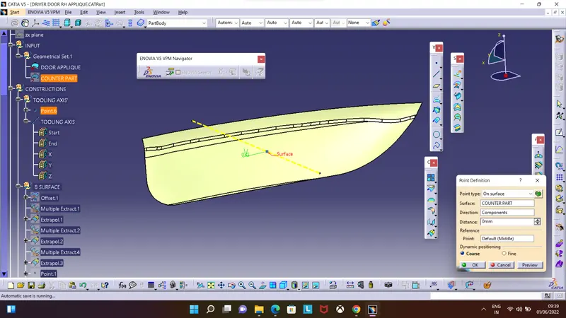
Fig: Tooling Axis
Creating Class B Surface
- Converting Class A surface into Class B surface at a offset distance of 2.5 mm.
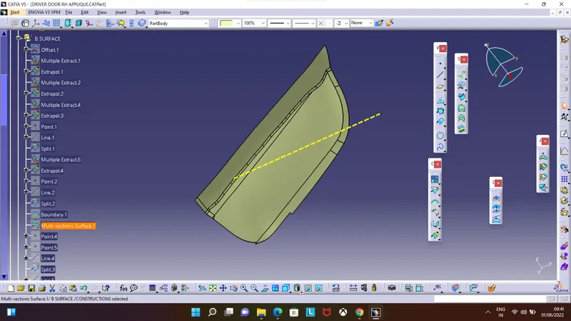
Fig: Class B Surface
Creating Class C Surface
- Creating Class C Surface to join both class A and B surface and convert them into solid part.
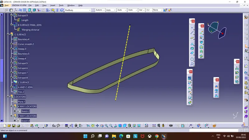
Fig: Class C Surface
- Joining Class A and Class C surface.
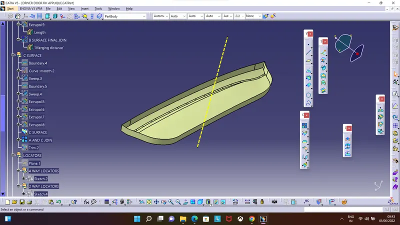
Fig: Combining of class A and Class C
- Converting it into solid part.
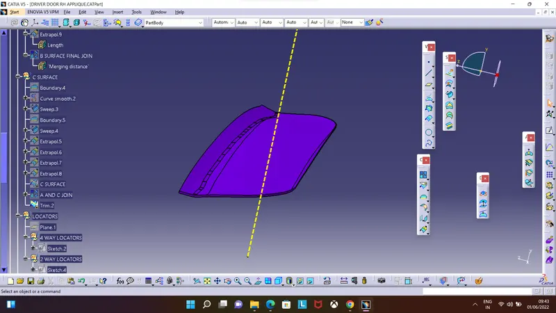
Fig: Solid Part
- Providing Thickness of 2mm to counter part.
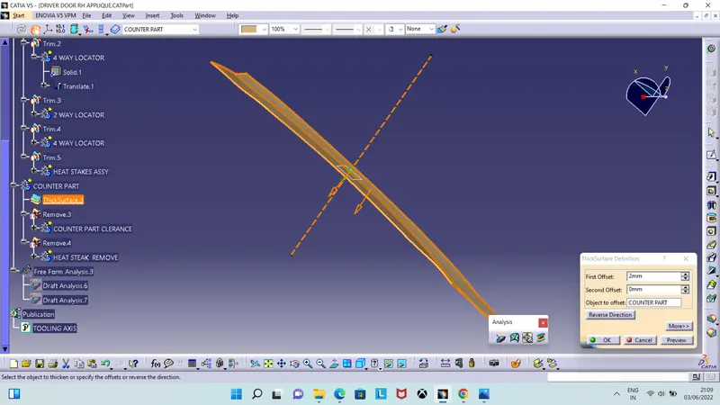
Fig: Counter Part
4 WAY AND 2 WAY LOCATORS
We will use the various clamp to hold the job to withstand the cutting forces. Ideally 3-2-1 principle is used to locate the job.
To locate and for fixing we have designed 4 way and 2 way locators.
- To create 4 way locator we use 2 lines intersecting each other.
- Surface extrude the intersectinng line and provide thickness of 1.3mm.
- Applying 0.5 degrees of draft on every face and providing chamfer on the edges.
- Similary 2 way locator is done using single line.
- Then translate the locator to desired position using coordinates.
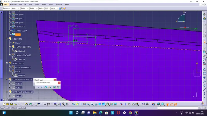
Fig: 4 way locator sketch
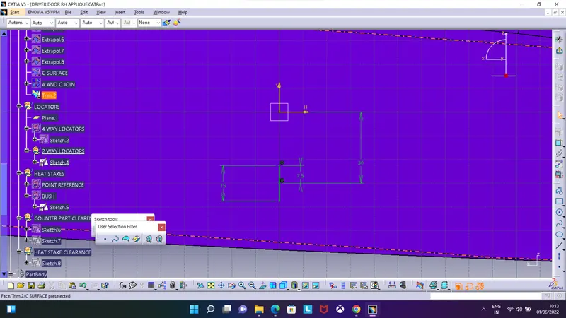
Fig: 2 Way locator sketch
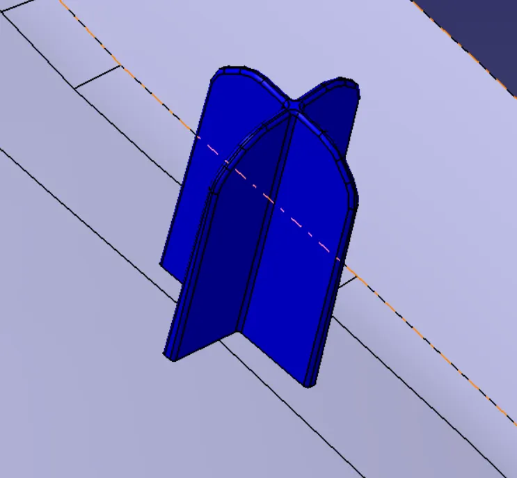
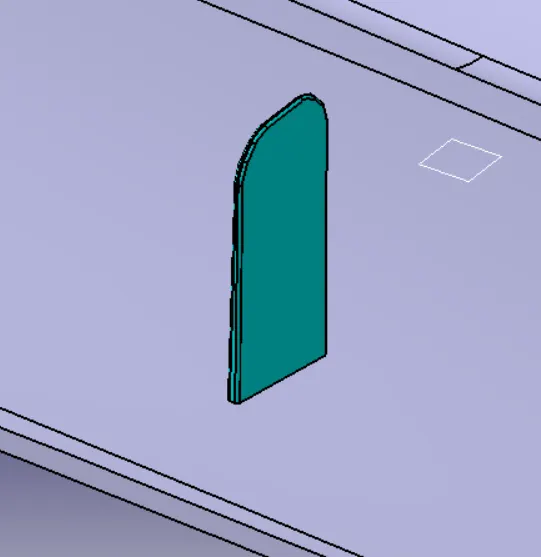
Fig: 4 Way locator Fig: 2 Way locator
HEAT STAKES
Thermal staking is an assembly method that uses the controlled melting and reforming of a plastic stud or boss to capture or lock another plastic or metal component of an assembly in place the plastic stud protudes through a hole in the component to be locked in place. The heated thermal tip contacts the top of the stud, which melts and fills the volume of the tip cavity to produce a head, locking the component in place.
- Extruding two circles having diameted 7mm and 5mm.
- Providing draft of 0.5 degree on both outside and inside surface of the heat stake.
- Translating the heat stake to desired positions.
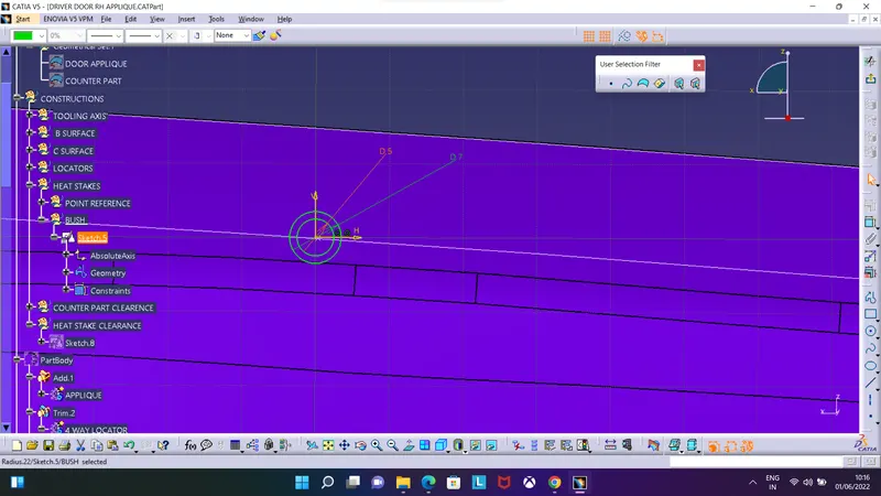
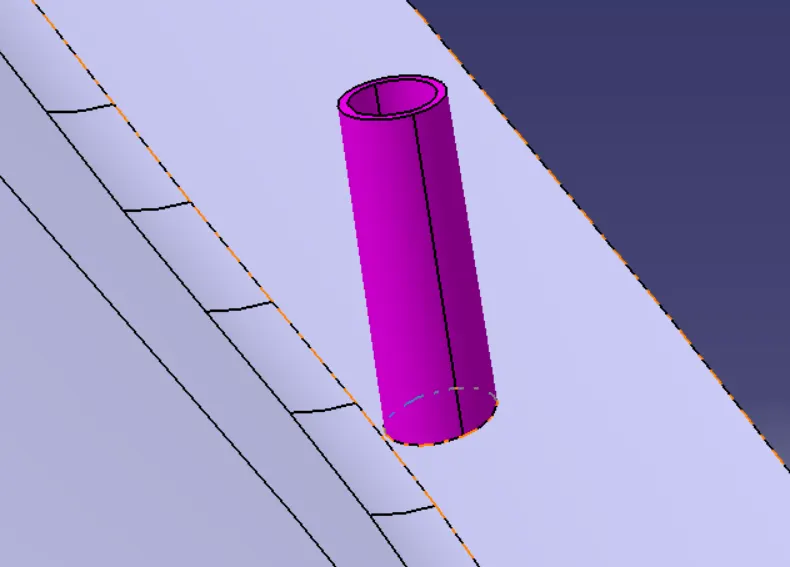
Fig: Heat Stake sketch Fig: Heat stake
Designing clearance on the counter part and making sure the clearence is 0.1 for locators and 0.5 for heat stakes
Fig: Counter Part
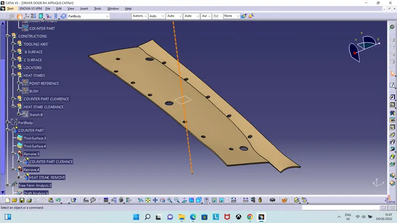
Fig: Clearence on counter part
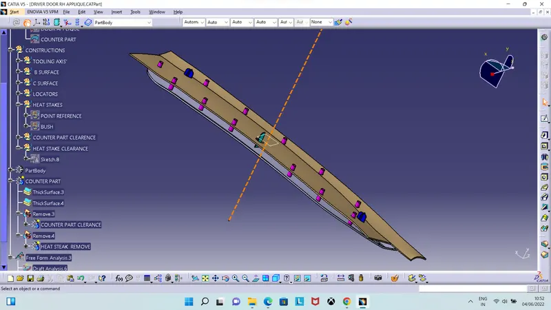
Fig: Door Applique
DRAFT ANALYSIS
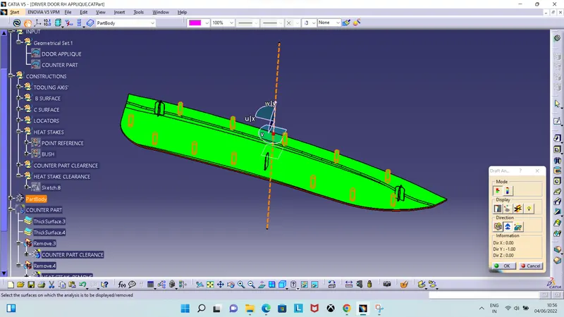
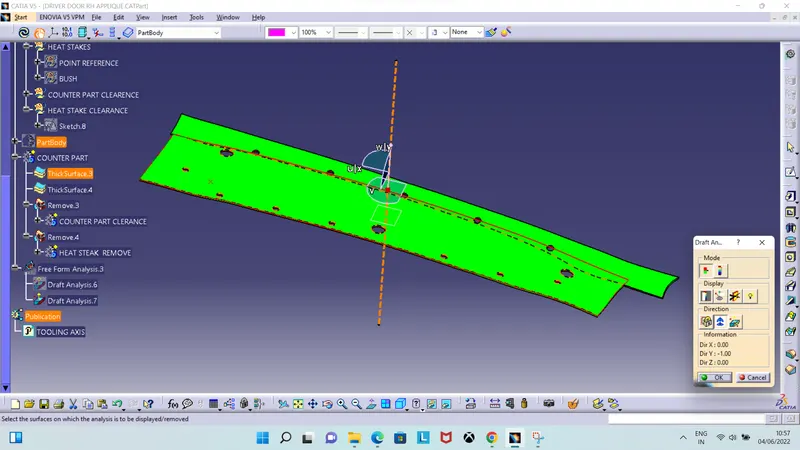
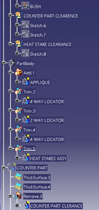
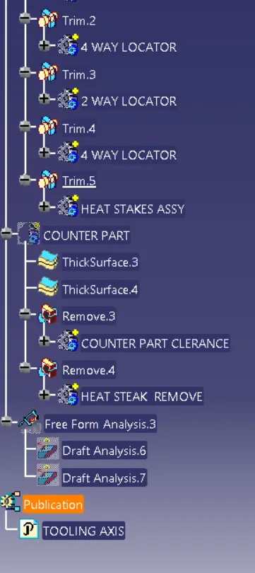
TREE
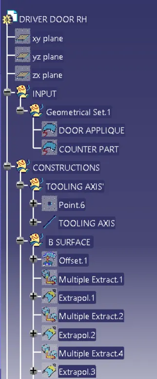
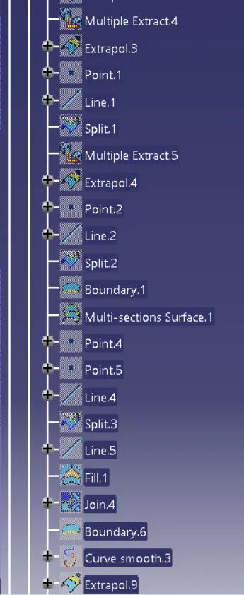
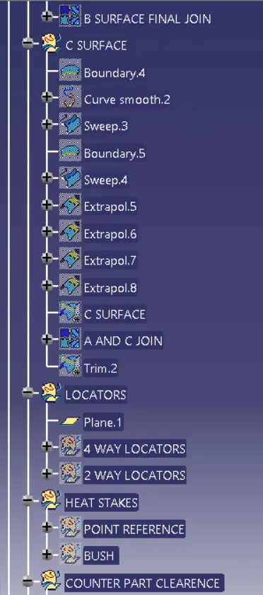
VIEWS
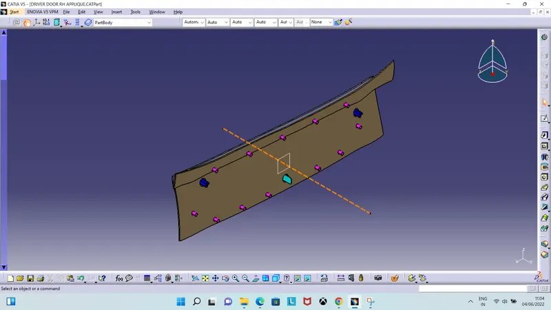
Fig: Isometric View
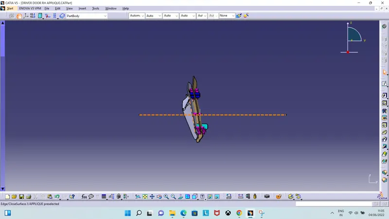
Fig: Front View
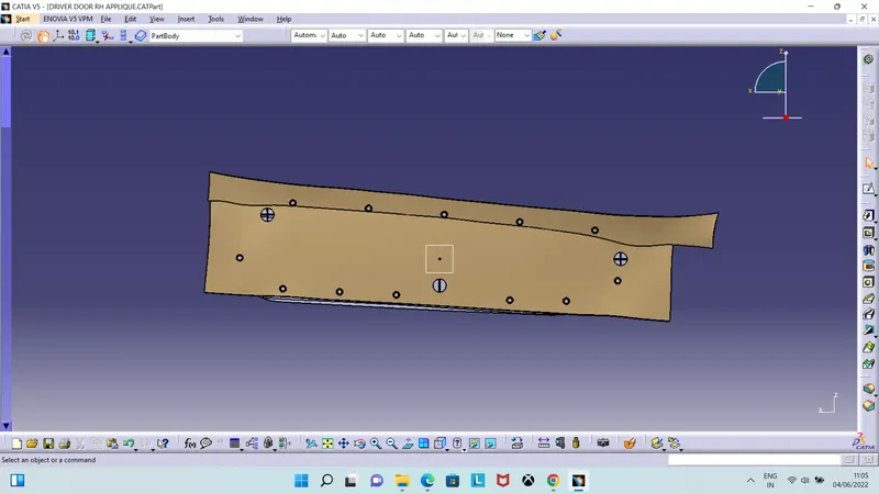
Fig: Side View
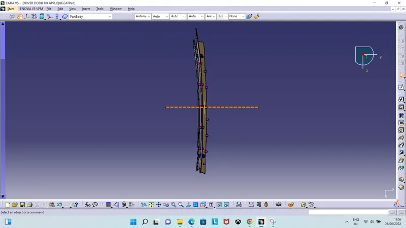
Fig: Top View