Week 9 - Project 1 - Door Applique Design with Engineering Features
Aim:
To Create the Door Applique Plastic component through the given Class-A surface and create a tooling axis for the given Class-A Surface meeting the requirements of the draft angle and at the end perform the Draft analysis on the model. Also create the Heat Stakes and the locators considering the design rules.
Procedure:
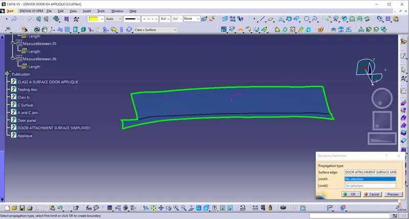
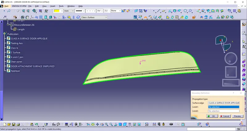
- Check whether the given class A surface is joined and there is no discontinuity.
- Use join or boundary command for this.
TOOLING AXIS CREATION:
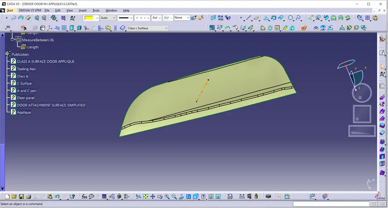
- Check for the suitable tooling direction. Usually,a perpendicular axis to large flat surface or hole is considered as a tooling axis.
- By inspecting it seems this part can be cleared in y direction.
- Create a point on the Class A surface. Create a line along the Y-axis.
DRAFT ANALYSIS ON CLASS A OF DOOR APPLIQUE
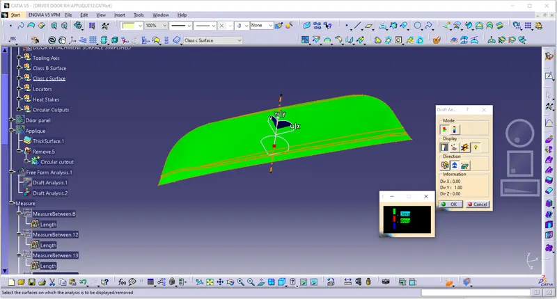
- Change to the material mode.
- Drag the compass and place it on to the tooling axis.
- Click on the surface and the surface will turn into Green.
- It means the angle of the surface is more than 3 degrees with respect to the tooling axis, and it can be cleared in tooling direction.
Creating class B Surface:
- Extract Class A and Offset it by 2.5mm which is thickness of the component.
- Then extrapolate it so that the Class C surface could intersect and will be easy to trim with it.
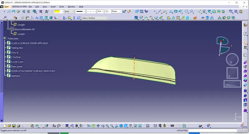
CLASS C DOOR APPLIQUE
- Extract boundary of Class A surface.
- Sweep it with the draft direction with 3 degrees.
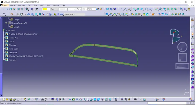
Joining A and C Surface:
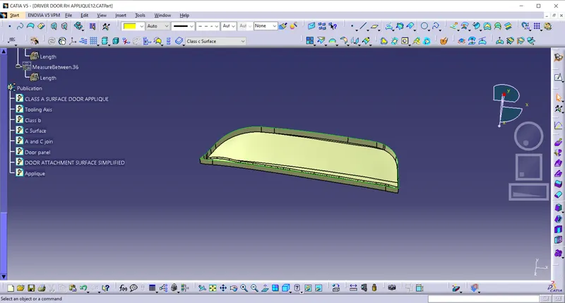
Final Trim :
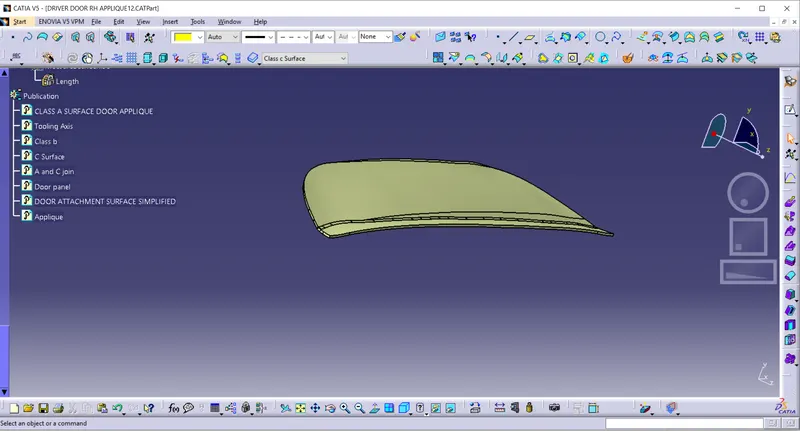
Creation OF B SIDE ENGINEERING FEATURES
Locators are placed according to the 3 - 2 - 1 principle which is basically a concept to fix a component to be machined or to be placed in an ideal position. There are a total of 12 degrees of freedom, 6 rotational and 6 translational.
In this, I need to fix any 11 degrees of freedom permanently and anyone to be clamped or fixed temporarily. In this scenario, Locators come into place.
Four-way Locators:
- Sketch for Four-way locators with 7.5mm on each side to arrest the Degrees of Freedom of the component and fix it.
- Pad it with thickness of 1.3mm for a depth of 15mm.
- Draft each face for 0.5 degrees.
- Then give chamfer of 3mm for easy sliding and fillet of 0.25mm to avoid sharp edges.
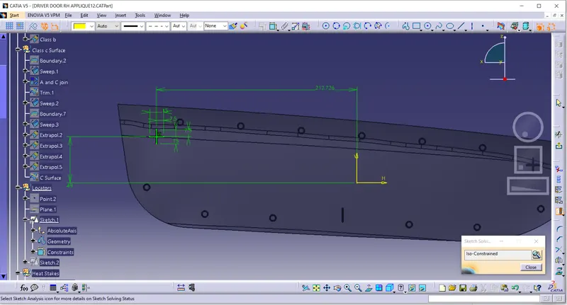
Two-way Locators:
- Sketch for Two-way locators with 7.5mm on each side to arrest the Degrees of Freedom of the component and fix it.
- Pad it with thickness of 1.3mm for a depth of 15mm.
- Draft each face for 0.5 degrees.
- Then give chamfer of 3mm for easy sliding and fillet of 0.25mm to avoid sharp edges.
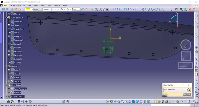
HEAT STAKES
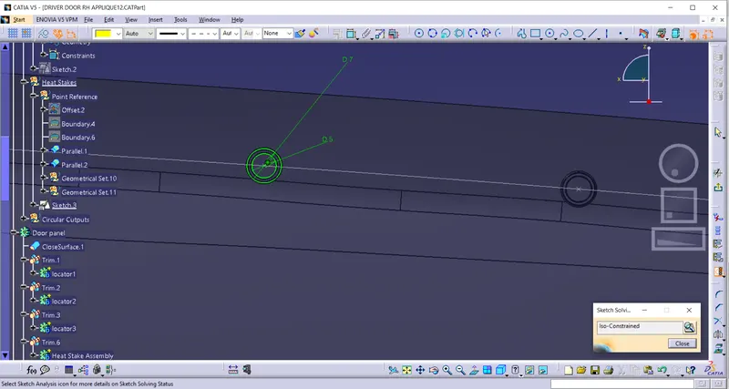
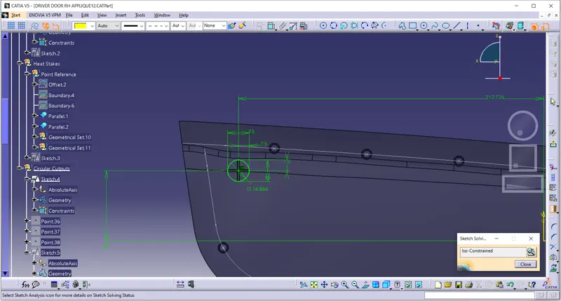
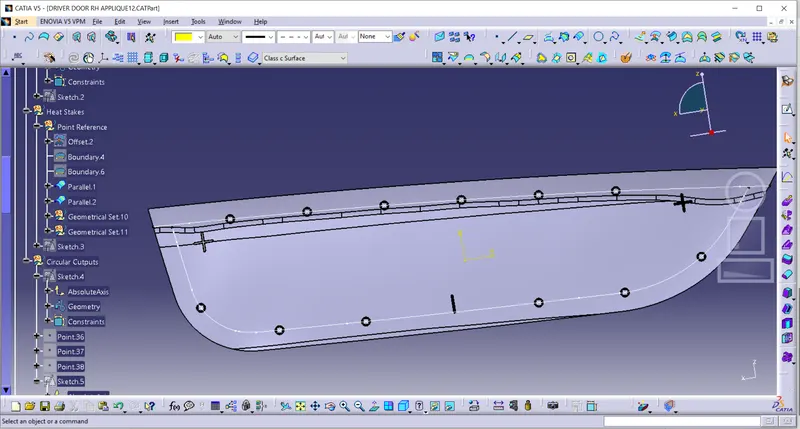
- Extract Boundary of Class A.Use parallel curve tool and get a parallel curve 15mm inside the boundary.
- Create points on to the curve for heat stakes. The Minimum distance between heat stakes must be 50mm.
- Sketch for heat stakes with two cocentric circles with inner circle diameter of 5mm and outer circle diameter of 6.5mm.
- Give 0.5 degree draft. Copy and paste special the body for 12 times(no of points on curve).
- Use point to point translation and translate the pasted bodies.
- Sketch for clearance cutouts for Heat stakes.
- The clearance for heat stakes must be 0.05mm on each side. So draw a circle of Diameter 6.6mm and pad it .
- Give Draft of 0.5 degrees.
- Copy and paste special the body for 12 times(no of points on curve).
- Use point to point translation and translate the pasted bodies.
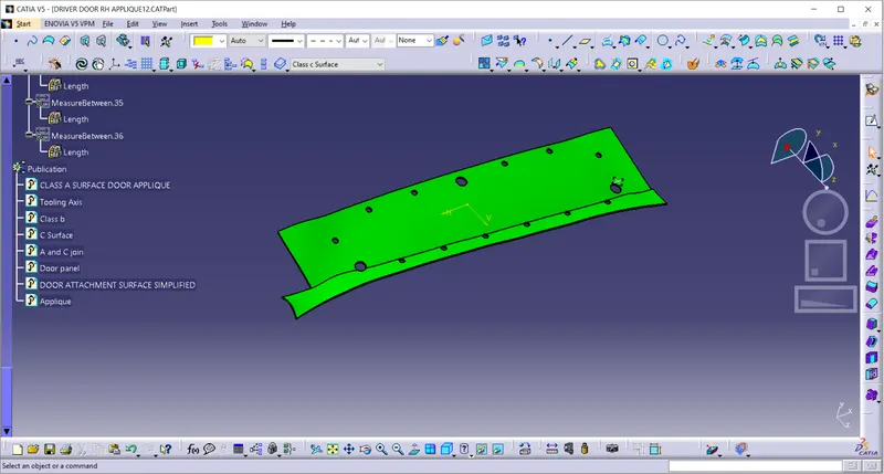
- Perform boolean operation and remove them from the door attachment body.
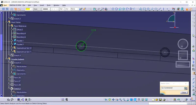
Clearance cutout for locators:
- Sketch for clearance cutouts for Locators.
- The clearance for locators must be 0.1mm on each side. So draw a circle of Diameter 15.2mm and pad it . Give Draft of 0.5 degrees and perform boolean operation and remove it from the door attachment body.
DRAFT ANALYSIS
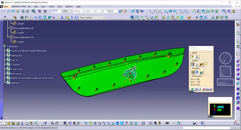
- Change to material mode. Drag the compass and place it on the tooling axis.
- Select the body. The body will turn green, which means all the features are drafted and clearing in the tooling direction.
Orientation Views:
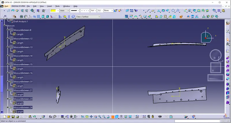
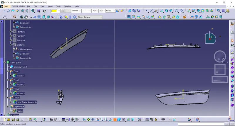
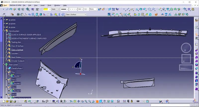
Tree Structure:
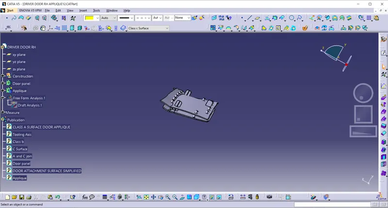
CONCLUSION:
- Tooling axis is created for the Class A of Door Applique. Draft Analysis is performed.
- The Class A of door is applique is used to develop the body.
- All the engineering features were created following the design guidelines.
- The Class A of Door attachment which is a sheet metal part is used to develop body by using thickness tool.
- Clearance cutouts were created on the Door Attachment for Locators and Heat stakes.
- The Draft Analysis is done on the Door applique body with the appropriate engineering features and all the features are found to be manufacturable.