Week 9 - Project 1 - Door Applique Design with Engineering Features
REPORT : DESIGN OF HEAT STAKES & DOOR APPLIQUE
INTRODUCTION-
The design of door applique on door panel which gives good aesthetic look.The heat stakes and locators are used to allign the door applique with door panel.To restrict all degree of freedomalong with locators, HEAT STAKES are used.The get joint the thermal heat is supplied to heat stakes.
DESIGN PROCEDURE-
- Create the door applique model from class A,B&C surfaces.
- Prepare attachment features like locators, heat stakes.
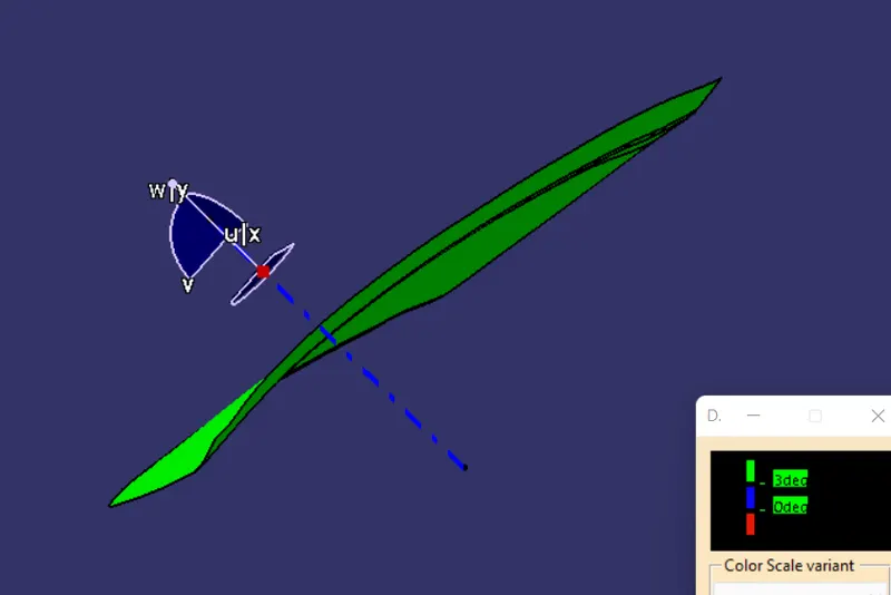
- Prepare the draft analysis on class A-surface,door applique solid model as well as on attachments features.
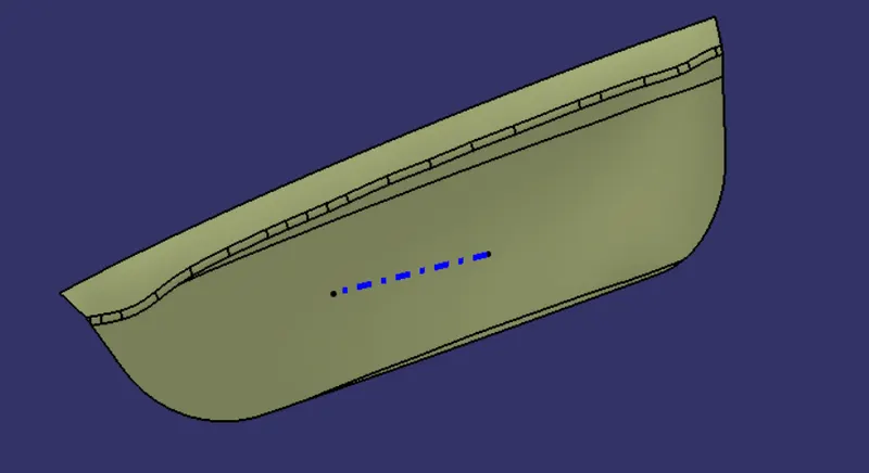
CLASS A-SURFACE-
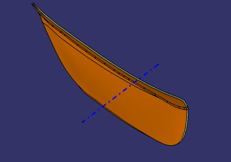
CLASS B-SURFACE
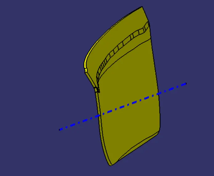
CLASS A&C JOIN
CLOSE SURFACE-
- Create the class A surface and offset it 2.5 mm thickness to genrate the class B-surface.
- Sweep the boundary edges of class A-surface to create class C-surface with outward draft angle 3 degree.
- Join the class A and Class c surface and Trim with Class B-surface to get the close surface of door applique part.
TOOLING AXIS-
- Extract the base surface of class A and then create the poiont on it.
- Draw the line passing through point and choose the direction.
- Also create normal line on extracted surface,both method wiil gives Tooling axis.
- Tooling axis gives us direction for opening of core and cavity from mould with zero defect on plastic components.
- With the help of tooling axis we can perform the draft analysis on components.
ATTACHMENTS FEATURES-
Generally locators,dog house,screw boss,heat stakes are used as attachments features for assembly od plastic component to class A and class B-surfaces.The attachments features are provided or designed on Class B- surface.The features restrict the nearly all degree of freedom of component.
- heat stakes-It is used to lock the final DOF which is not locked by other features.It is fusible material,can be melted on thermal heating.The main intention of heat stakes to melt on heating and fiil the clearence and make solid joint bitween the two mating components.
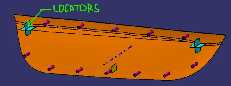
1. design procedure of locators-(four way & two way locators)-
- Create the point and plane on Door panel surface and sketch the four way locator with specified diamensions.
- Pad the sketch with suitable distance make sure that it intersect or go beyond the class A-surface.
- Make the union trim so that the extra part will get trim out.
- To make multiple locator,copy the previous one and paste it as special anduse the translate feature to locate the locator.
- The locators gives maximum strength to components in assembly mode.
- Make sure the locators height crss the door panel so it would help to easy fitting.
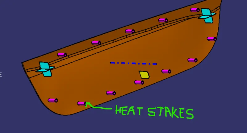
2. Design procedure of Heat stakes-
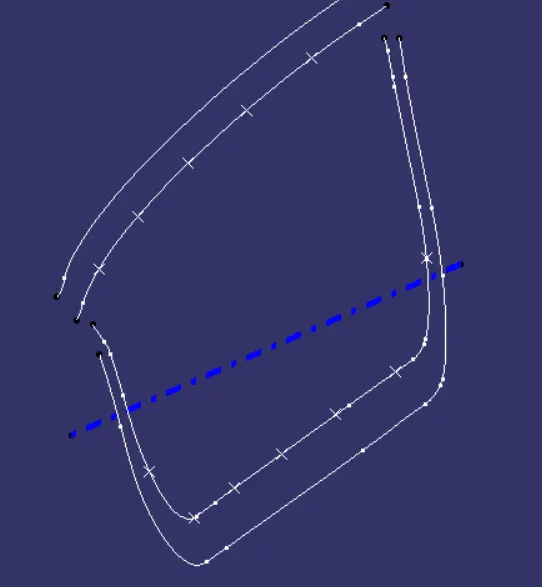
- Extract the class A-surface,offset it and extract boundary edges.
- Use the parallel curve to offset the boundary edges with distance 10 mm.
- Create the multiple points on curve by using point repetition command which help to get position od heat stakes.
- Draw the heatstake with dia.5 and dia.7 mm.and pad it with appropriate distance.It should be intersect the applique body and trim it .
- Translate the heat stake body with respect to point positions so that we will get multiple heatstakes and assemble it with door applique body by using union trim command.
3.counter part clearences-
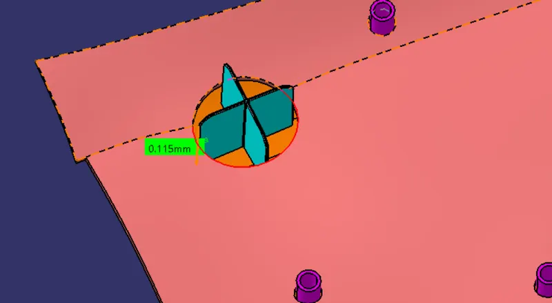
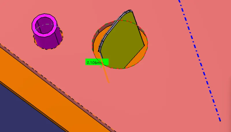
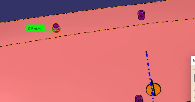
- The clearence wiil be provided bitween door panel and attachments features.The clearence value varries with attachments feature like for locators it should be 0.1 mm per side and for heatstakes it should be 0.5 mm per side.
- Generally for clearence portion the circular cut out is prefered because of it's design simplicity.
- The cut-out depth value should be door panel thickness.
- The clearence type should be push fit or press fit which help to fit or hold the door applique and door panel for longlife.
A) locator clearence-
B) heat stakes clearence-
# DOOR APPLIQUE AND DOOR PANEL-
The door applique and Door panel are connected by locators and heat stakes.The door applique used for aesthetic purpose and joint with panel door .
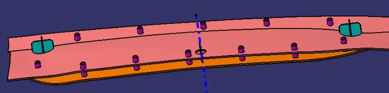
fig.Door applique & door panel.
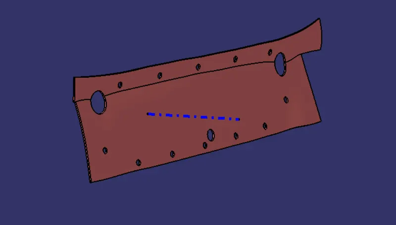
fig.Door panel
DRAFT ANALYSIS OF SCREW BOSS AND DOG HOUSE-
**Procedure to create Draft Analysis-
1.Open the part file in Catia workbench.
2.Apply the material for part.For that go to view feature>Render style>Customize view parameter.
3.For draft analysis we have to select Insert>Analysis>Feature draft Analysis.Then there will be opening the Draft analysis dialogue box with showing icons like mode, display and direction.
4.Move the compass towards the tooling axis and coinside it with tooling axis.If you want to fix the compass then click on lock icon .
To start the analysis-
1.Select the surface of Part that we want to analysis.
2. click on draft analysis icon .
3.MODE OPTION-
In dialoue box showing mode option with quick & full analysis mode.In that mode feature we can understand the different angle range value in colour format which indicate part is in correct drafft mode or not.The default mode is the quick mode. It simplifies the analysis in that it displays only three color ranges.
* Doble click on colour range which display in dialogue box and we can change the colour range.
*Also by double click on the angle value ,we can modify it.
*The colour mode and respective Draft angle value is set in mode dialogue box.
- When the Draft angle value of the surface is equal or smaller than graduated (fixed in dialogue box) value,the colour will be applied as per graduated value to the surface.
- When the Draft angle value of the surface is greater than greatest value of graduated,the colour of graduated value is applied.
4.DISPLAY OPTION-
- colour scale-this dialog box only appears in edition mode.Means we have to activate Full mode or Quick mode analysis.
- Angle Pointer-activate the pointer and move it over the surface which showing various draft value at different locations.
Arrows are displayed under the pointer, identifying the normal to the surface at the pointer location (green arrow), the draft direction (red arrow), and the tangent (blue arrow). As you move the pointer over the surface, the display is dynamically updated. Furthermore, circles are displayed indicating the plane tangent to the surface at this point.
3.No highlighted & Representation icon-This feature gives option like on/ off the highligh portion of part.As it enable ,it will show all edges in colour (highlight) format.
4.LIGHT EFFECT-This feature helps to understand the visualisation effect of part under light effect.This light effect will affect the visualiser's eye.
5.Inverse direction- It allows to change the direction of draft angle of selected part.As the we click on reverse direction then there is changing gaduated colour effect ( in negative).It shows the BLUE colour.
5. DIRECTION -
- LOCKED DIRECTION- In that we can lock or unlock the draft angle direction,a plane,a Face which is used in current analysis.
- COMPASS- It is used to define the new or current draft direction.To set the compass direction on Tooling Axis,we have to move or pull the compass origin and coinside with tooling axis.
6.Once we have finished the analysing the surface by applying propper elements CLICK on OK icon in DRAFT ANALYSIS DIALOGUE BOX.The analysis is added to tree chart of part.
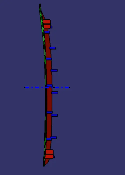
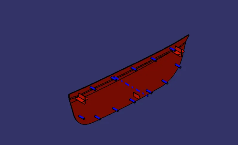
## Draft analysis pictures of door applique and heat stakes features-
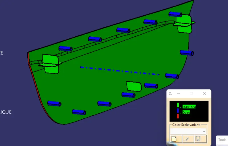
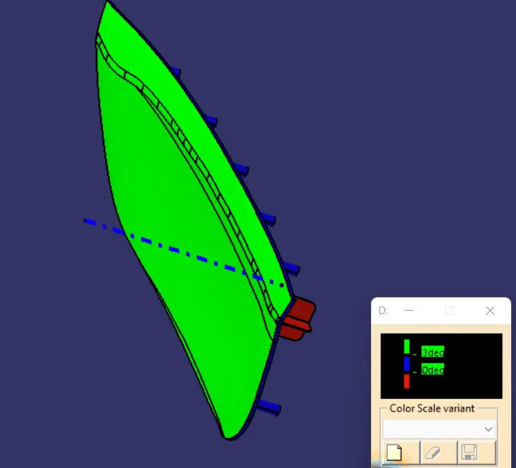
1.front view-
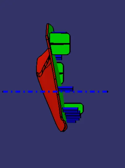
2.side view
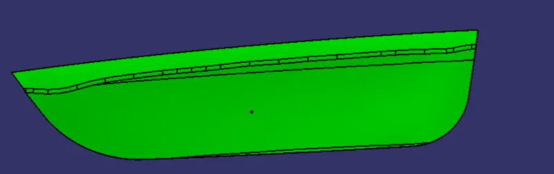
3.Top view-
4.Isometric view-
#CONCLUSION-
- Learn to uses of attachment features.
- Learn about heat stakes and it's uses,importance.
- Heat stakes genarally fusible material which helps to join the matting parts.
- Learn to point repetation features for multiple translate posotion.