Week 8 - Challenge 3 - Switch Bezel Design
REPORT- SWITCH BEZEL DESIGN
OVERVIEW ON SWITCH BEZEL-
Designed to match the appearance of the original,Door Window Bezel restores the overall aesthetic design of the vehicles door panel and holds the window switches in place. Direct replacement for a proper fit every time.
INTRODUCTION -
Automotive plastic design engineer while creating plastic switch bezel part that can be used mostly in automobiles, designer should have ability to create CLASS A SURFACE, B-SURFACE & C SURFACE.
Designers of plastic parts and mold tooling manufacturers can use the Draft Analysis tool to check the correct application of draft to the faces of their part. With draft analysis, you can verify draft angles, examine angle changes within a face, as well as locate parting lines, injection, and ejection surfaces in parts.
This task shows how to analyze the draft angle on a surface. The Draft analysis command enables you to detect if the part you drafted will be easily removed.
A Draft Angle describes the amount of taper for molded or cast parts perpendicular to the parting line.
DESIGN PROCESS-
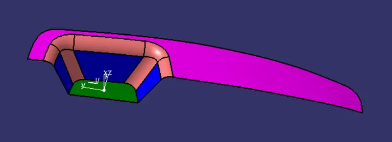
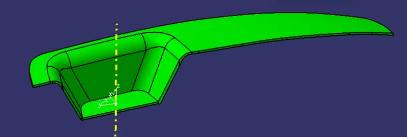
CLASS A-SURFACE :-Class A surfaces is a term used in most in automotive design to describe a set of freeform surfaces of high efficiency and quality. Actually it is nothing more than saying the surfaces have curvature and tangency alignment. It is smooth looking reflective surface with no distortion of light highlites, which moves in a smooth uniform designer intended formations.
- Class A surfaces must have coincident curvature at least every 100 mm of contour of two neighboring patches.
- Class A surface can be defined as any surface that has styling intent.
- Class A surfacing is done using computer-aided industrial design applications.
- Completion surfaces must be designed in all detail
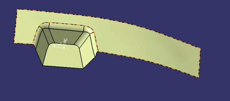
CLASS B-SURFACE :-Class B-surface also called as engineering surface.It is replica of Class A surface and created by offseting the surface with appropriate thickness.In B surface we have uses various features like TRIM,SPLIT,EXTRAPOLATE etc.. to get riplica of A-surface.
- Only rounded contours are represented on the surface that is always fixed to the body
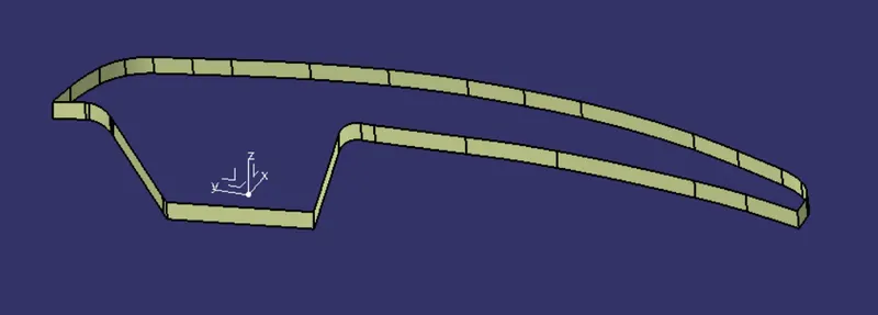
CLASS C-SURFACE :-It is bridge between Class A and Class B surfaces means the surface which join the A&B surface by giving draft direction.Class C-surface gives actual part visibility by applying thickness of that part.
- Completion surfaces are not required,gaps are represented by double lines drafted onto the aesthetic surface
on the combining of Class A,Class B & Class C surfaceses the final part is get ready for manufacturing purpose.
CLASS A-SURFACE:-
CLASS B-SURFACCE:-
CLASS C-SURFACE :-
PROCEDURE -
*Procedure to create TOOLING Axis by using BISECTING method-
The bisecting method generally used for tapered object or part which having drafted feature with some angles.For that tapered part we have to decide correct tooling axis and which is very difficult.
In switch bezel we see mostly plane surfaces and intersecting surface found in Y-direction only.Also there is plane base intersecting to wall surface is found.
So that we have to create tooling axis with bisecting the line1 which is normal to base surface and line 2 which is 3 degreedeviate to coinsidence line of class A intersecting surface.
To create TOOLING AXIS go to LINE>BISECTING>select>line1 & line2>select intersection piont>OK.
1.Open part-To creating Tooling part we have to open the part that have CLASS-A Surface.
2.Geometric Set- we creating geometric set,in that all sketches should be involved.
3.Boundary surface- To create tooling axis it is first step to create the boundary by selecting surface.Here we have to get the 3D sketch of part.
So go to SHAPE>GENERATIVE SHAPE DESIGN>OPERATION TOOL >Select BOUNDARY.
4.Extract base surface-To getting Tooling Axis we have plane base surface on Class A-surface so by extracting base and creating point and normal line with help of new axis system.
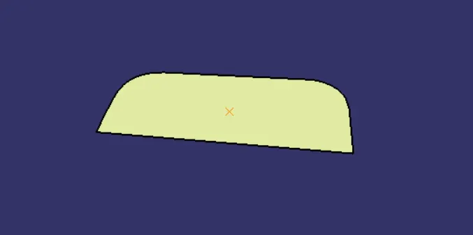
5.Tooling Axis- To obtain the tooling axis,we have to select both normal line 1 and deviated line 2 of intersecting line surface Which gives us the combine form of these axis and this axis is called as Tooling Axis.
go to line>bisect line>select line 1&2>Select point>ok
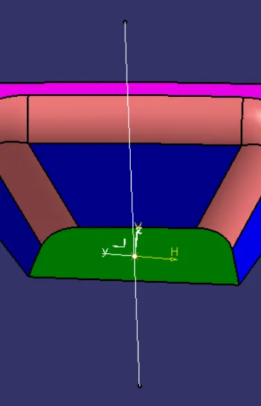
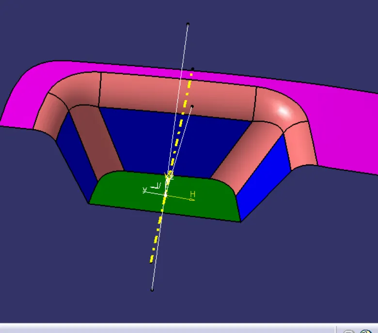
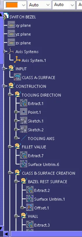
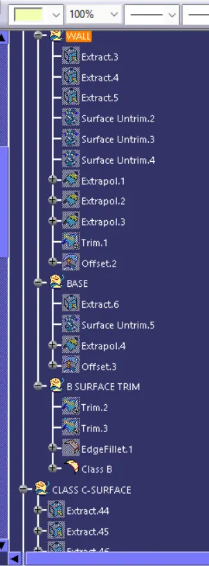
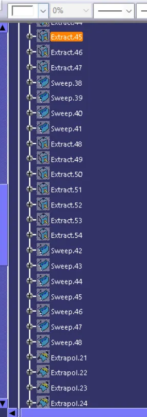
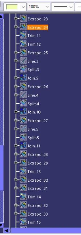
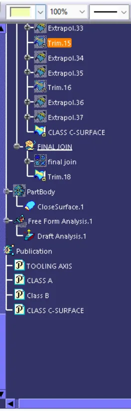
Feature tree chart-
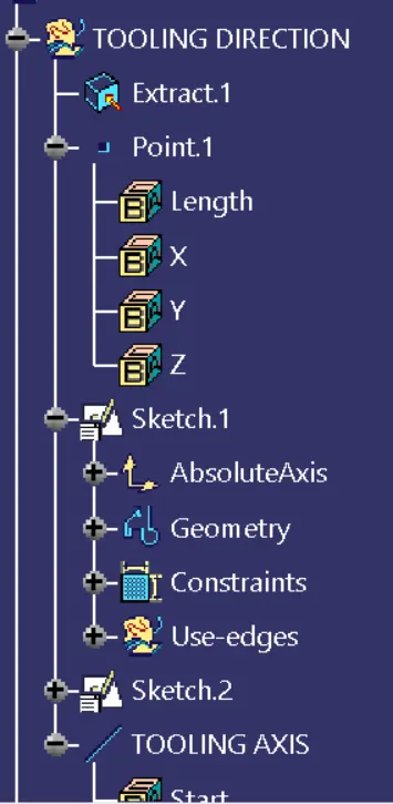
So that in this way by using Bisecting method we can create the TOOLING AXIS.
Now after creating tooling axis we can move for Draft angle Analysis.The procedure of draft analysis are as followes.
*Procedure to create Draft Analysis-
1.Open the part file in Catia workbench.
2.Apply the material for part.For that go to view feature>Render style>Customize view parameter.
3.For draft analysis we have to select Insert>Analysis>Feature draft Analysis.Then there will be opening the Draft analysis dialogue box with showing icons like mode, display and direction.
4.Move the compass towards the tooling axis and coinside it with tooling axis.If you want to fix the compass then click on lock icon .
To start the analysis-
1.Select the surface of Part that we want to analysis.
2. click on draft analysis icon .
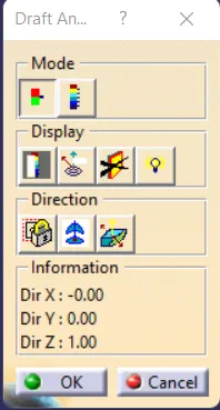
3.MODE OPTION-
In dialoue box showing mode option with quick & full analysis mode.In that mode feature we can understand the different angle range value in colour format which indicate part is in correct drafft mode or not.
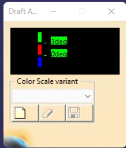
The default mode is the quick mode. It simplifies the analysis in that it displays only three color ranges.
* QUICK MODE-
*FULL MODE-
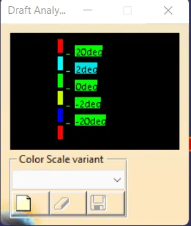
* Doble click on colour range which display in dialogue box and we can change the colour range.
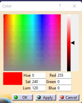
*Also by double click on the angle value ,we can modify it.
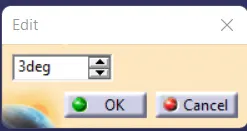
*The colour mode and respective Draft angle value is set in mode dialogue box.
- When the Draft angle value of the surface is equal or smaller than graduated (fixed in dialogue box) value,the colour will be applied as per graduated value to the surface.
- When the Draft angle value of the surface is greater than greatest value of graduated,the colour of graduated value is applied.
4.DISPLAY OPTION-
- colour scale-this dialog box only appears in edition mode.Means we have to activate Full mode or Quick mode analysis.
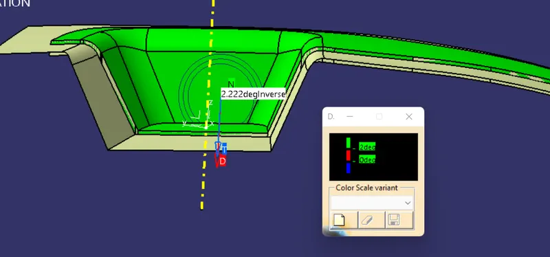
- Angle Pointer-activate the pointer and move it over the surface which showing various draft value at different locations.
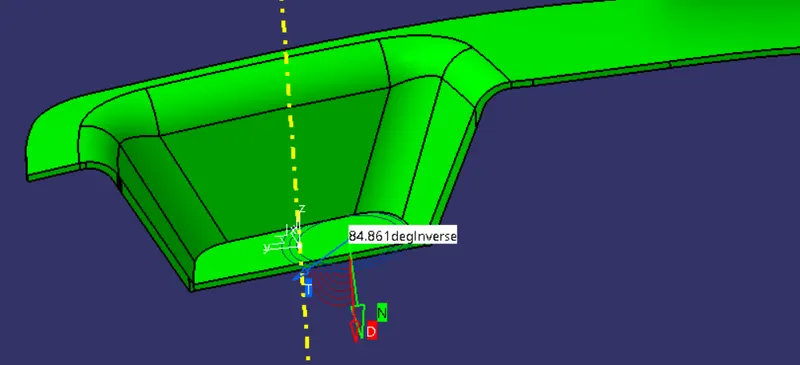
Arrows are displayed under the pointer, identifying the normal to the surface at the pointer location (green arrow), the draft direction (red arrow), and the tangent (blue arrow). As you move the pointer over the surface, the display is dynamically updated. Furthermore, circles are displayed indicating the plane tangent to the surface at this point.
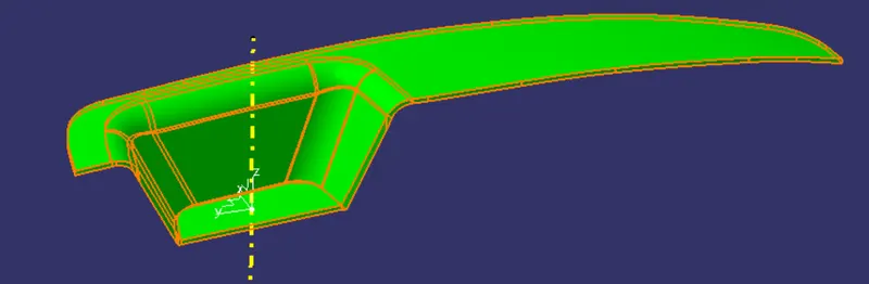
3.No highlighted & Representation icon-This feature gives option like on/ off the highligh portion of part.As it enable ,it will show all edges in colour (highlight) format.
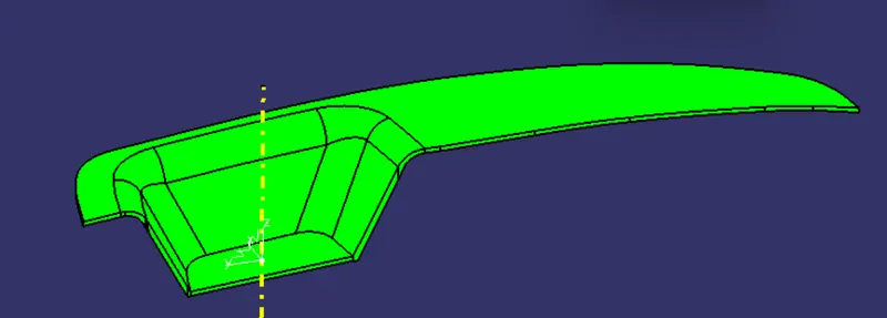
4.LIGHT EFFECT-This feature helps to understand the visualisation effect of part under light effect.This light effect will affect the visualiser's eye.
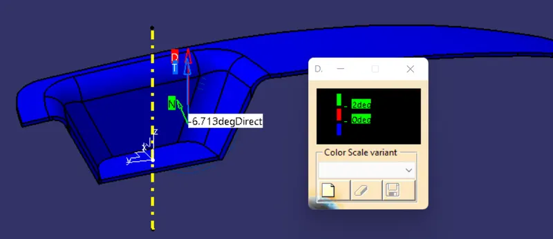
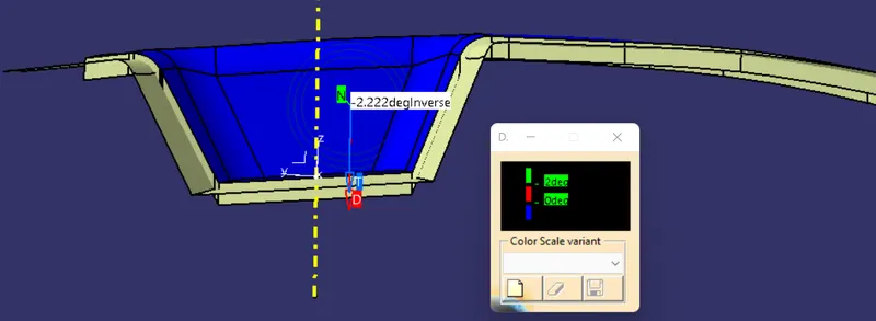
5.Inverse direction- It allows to change the direction of draft angle of selected part.As the we click on reverse direction then there is changing gaduated colour effect ( in negative).It shows the BLUE colour.
5. DIRECTION -
- LOCKED DIRECTION- In that we can lock or unlock the draft angle direction,a plane,a Face which is used in current analysis.
- COMPASS- It is used to define the new or current draft direction.To set the compass direction on Tooling Axis,we have to move or pull the compass origin and coinside with tooling axis.
6.Once we have finished the analysing the surface by applying propper elements CLICK on OK icon in DRAFT ANALYSIS DIALOGUE BOX.The analysis is added to tree chart of part.
IN this way we can genrate the report for Draft Analysis for a given part by using Feature Draft Analysis.
The images of Draft Analysis are as follow-
1.Quick Analysis mode- with color scale variant & Complete draft Analysis
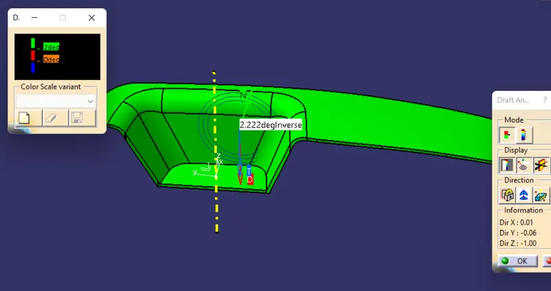
2.Full Analysis mode- with color scale variant & Complete draft Analysis
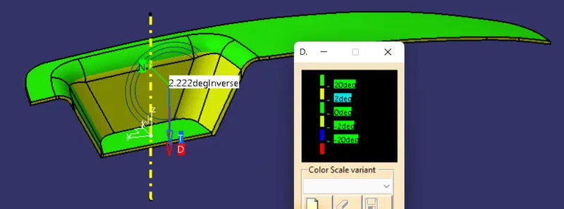
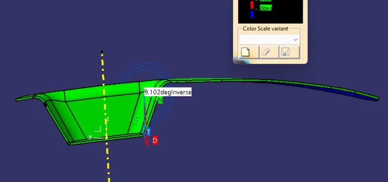
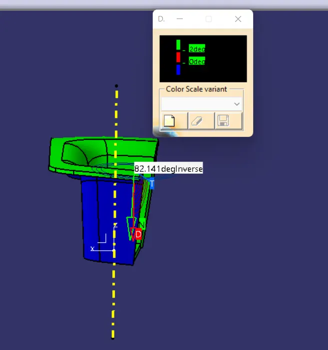
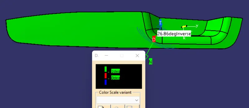
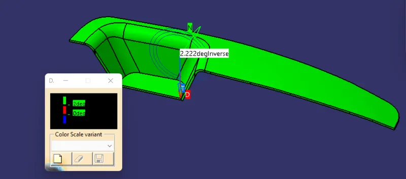
3.Inverse Draft Direction Analysis-
*Different orintation views of switch bezel with Class A,B&class C-surfaces-
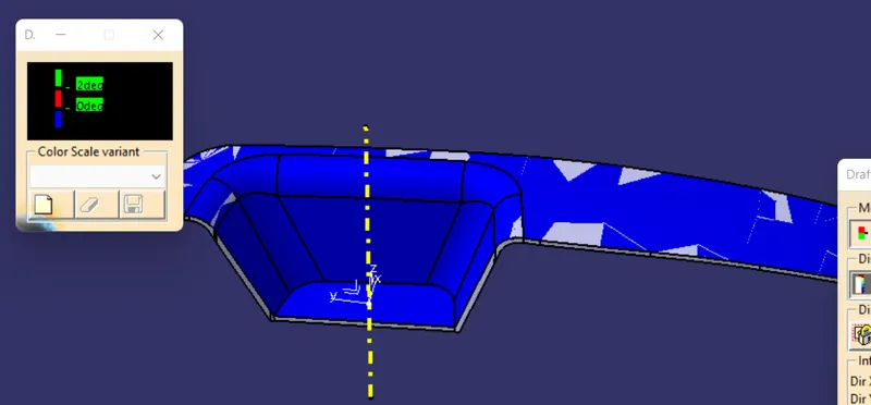
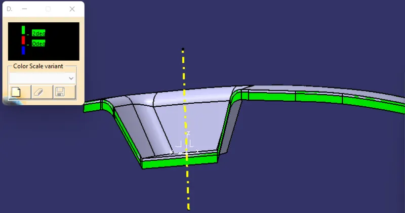
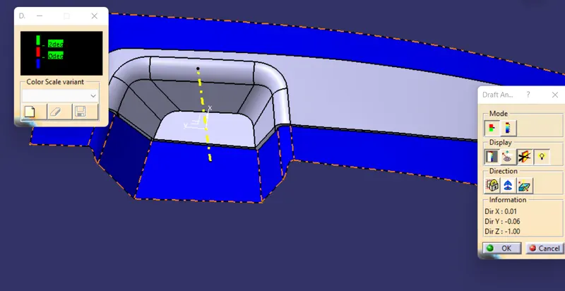
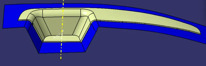
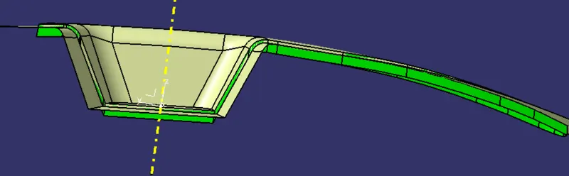
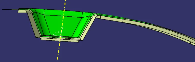
*Front view-
*Side view-
*Top view-
*isometric view-
**RESULT OF ANALYSIS-
1.GREEN COLOR- Here Green color shows that the draft analysis is positive and there is no error in model.The angle more than 2 degree is considered as positive draft angle.
2.Blue & Red Color- Red and Blue color shows negative draft angle.
*CONCLUSION-
In Draft analysis we can learn about provided draft angle is correct or not.Draft angle decide the part ejection from mold with smoothly.Draft analysis shows part whethere positive or negative draft angle.
Also we can learn how to generate Tooling axis with the help of intersecting the surface along with creating dummy axis by using BISECTING line method and finally we create main tooling axis.
-----------------------------------------------------------------------------------------------------------------------------------------------------------------------------------------------------------------------------------------------------------------------