Photo Realistic Rendering
|
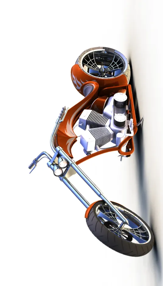
PROJECT- RENDERING OF AMERICAN CHOPPER ABSTRACT In this project we understand different feature, tools and Rendering tool uses. Rendering process help to Understand the realistic view of models. submitted by- Sambhaji Dalave |
 |
INDEX
|
SR.NO. |
CONTENT |
PAGE NO. |
|
1. |
ABSTRACT |
1 |
|
2. |
OBJECTIVE |
3 |
|
3. |
INTRODUCTION |
3 |
|
4. |
DESIGN FLOWCHART |
4 |
|
5. |
OVERVIEW OF FEATURES TOOL |
5-6 |
|
6. |
BRIEF INTODUCTION ABOUT CHOPPER COMPONENT |
7-15 |
|
7. |
ASSEMBLY AND PROJECTION METHOD |
16 |
|
8. |
FINAL ASSEMBLY VIEWS |
17-19 |
|
9. |
RENDERING VIEWS WITH BACKGROUND VIEW |
20-22 |
|
10. |
CAMERA SETUP VIEW |
22 |
|
11. |
RENDERING VIEWS WITH REFLECTING BLACK STUDIO SCENE |
23-24 |
OBJECTIVE –
Sketching and creating 3D model of respective parts for American chopper bike. To understand and application of assembly relation, mates during chopper assembly. Also apply surfacing tool to creation of Fuel tank.
More important to understand and use of photo view 360, solid work visualization tool for purpose of accurate realistic view of American chopper.
INTRODUCTION –
Solid work allows engineer to creating model as per their design concept.Engineer can easily create model and convert into 3D model which may be complicated or not because of solid work handy free feature tools. We can create 3D model with proper dimensions, assembly of parts, extreme surfacing feature tools, rendering the model for more realistic view.
Solid work allows to use the different type of materials and appearance look for model to look like it’s accurate property and it more important to design engineer.by using solid work visualize we can use various rendering background and environments.
About American chopper bike, it is custom bike where it’s customizations will considered as per rider comfortless choice. American chopper bike comes with very comfortable design and with heavy engine. In this project we can use blue print of chopper to easy and more accurate with time consuming for creation chopper model. By using rendering feature, we will understand real view of American chopper.
DESIGN FLOWCHART –
Analysing the blue print of American chopper
Creating propper sketch environment in solid work
2D drawing of all parts with diamensions
Convert 2D to 3D model of parts
Providing proper shape, pattern, required feature tool
Applying appearance, material to the model
Assemble the all part together with mates
Final rendering and set background
OVERVIEW OF FEATURE APPLIED –
Solid work gives various features to making 3D model from 2D sketches. Tools used into solid work very handy and easy to use at any time. feature allows repairs model at any environment. Some of feature that we used in the American chopper listed below.
- Extrude Boss
- Extrude Cut
- Shell
- Revolve Boss
- Fillet
- Camphor
- Swept Boss
- Loft Boss
- Pattern
- Mirror
- Split tool
- Dome
- Appearance
- Composite curve
- Project curve
- Photo view 360
- Rendering
- Visualize
Extrude Boss – Extrude Boss feature allows to convert 2D fully defined sketch into 3D appropriate model with variable dimension.
Extrude cut – Extrude cut feature used to cut the unwanted part from model.
Fillet – It help to converts sharp corner into smooth and round surface.
Shell – Shell feature allows to convert solid model into hollow with desired thickness.
Revolve Boss – This feature allows to revolve the 2D sketch into solid round model by selecting reference axis.
Swept Boss – This feature also helps to create solid body by selecting reference curve.
Loft Boss – Loft boss feature used to create solid body of two different sketch.
Pattern – Pattern feature is very useful and easy tool. It helps to create same feature into multiple time.
Mirror – For developing same body mirror tool is used. For mirror we need to select reference plane.
Split Tool – Split tool allow us to cut or divide the 3D model or solid body into two parts with vertical, horizontal and some angle as well.
Dome – dome feature fives us to oval or elliptical, circular shape.
Appearance – Appearance feature allow to applying color and material to 3D model.
Composite curve – This feature helps to combine two different projected curves in single plane.
Projected Curve – In solid work projected curve feature very useful it allows to connect sketches of two different plane into single feature.
Rendering – Rendering is one of the great features where we create real scene of 3D model by applying background.
Visualize – This feature is part of Rendering also in which we make model exact real time model by using various environments effect, background, cameras mode.
AMERICAN CHOPPER COMPONENT DETAIL VIEW
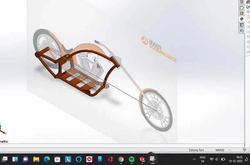
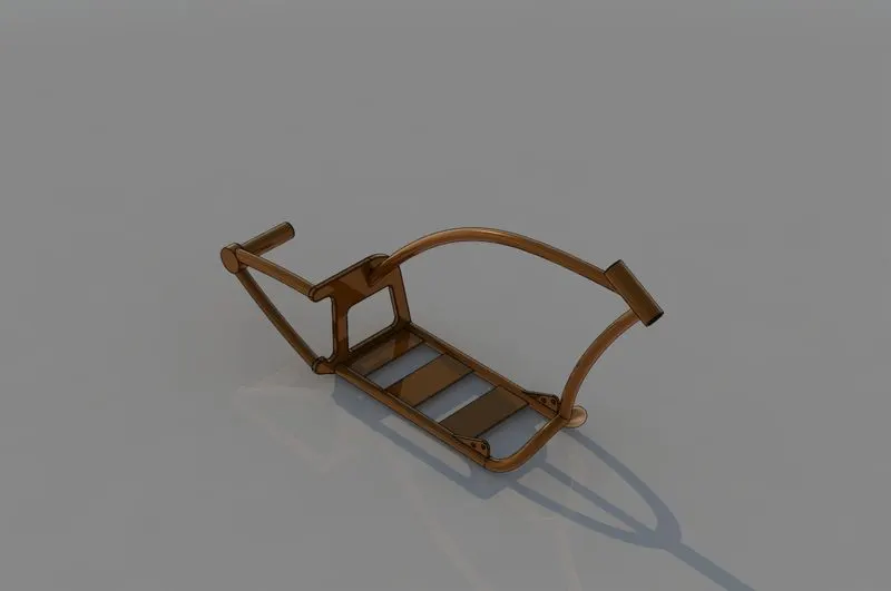
1.CHASSIS – It is main body part of chopper where all components are assembled with respect to chassis position. The feature used for chassis,
- Projected curve
- Swept boss
- Extrude Boss
- Extrude Cut
- Dome
- Fillet, Chamfer
- Split
- Combine
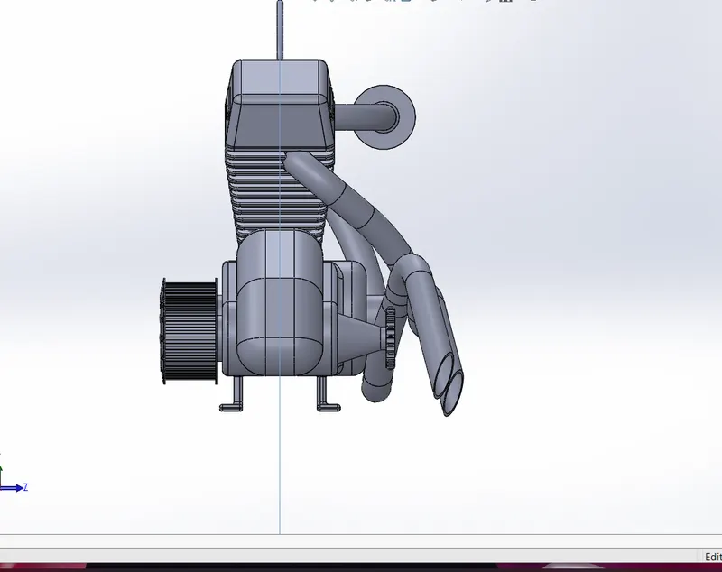
2.Engine -engine is most important component of any transmission vehicle. Engine allow the bike to relative motion. Feature used in engine model are-
- Projected curve
- Combine curve
- Extrude Boss/Cut
- Revolve Boss
- Swept Boss
- Split
- Fillet
- Linear pattern
- Circular pattern
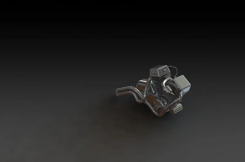
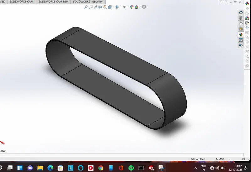
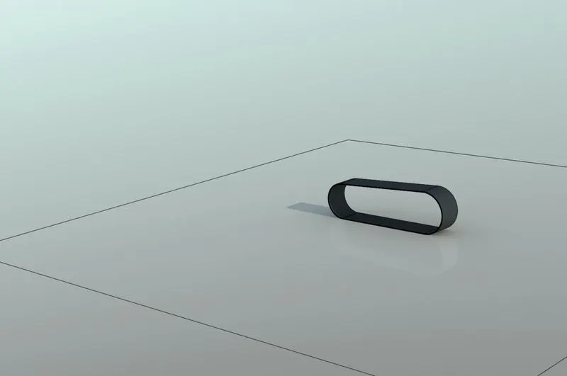
3.Transmission Belt- Transmission belt used to transfer the power from one pulley to another pulley. Feature used in belt are-
- Extrude Boss
- Fillet
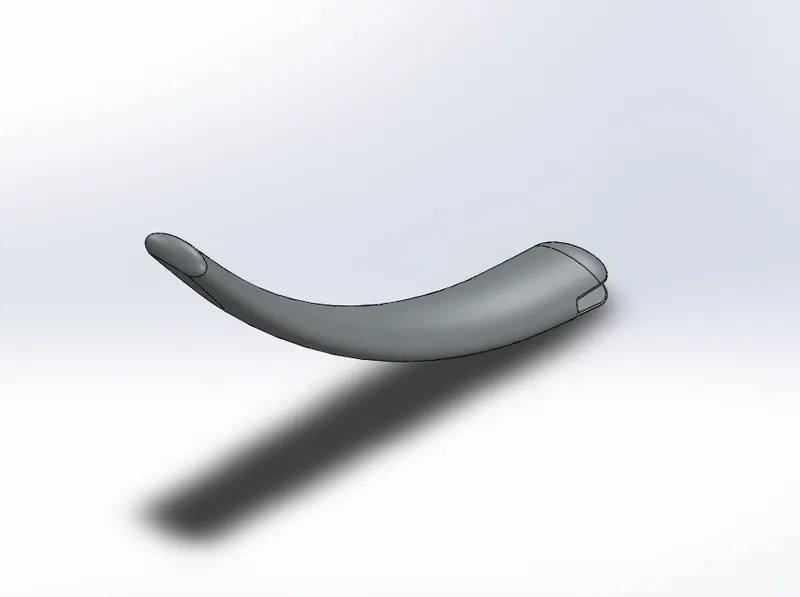
4.Pedal – Pedal allow to driver to control the bike speed by applying break. The feature used in pedal are-
- Extrude Boss
- Fillet
- Dome
- Linear pattern
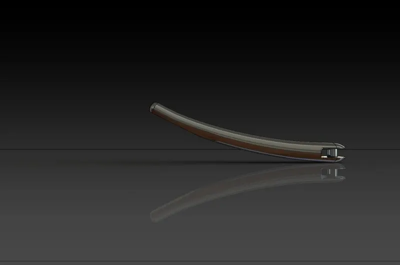
5.Kickstand -It is more important component of all two -wheeler. It allows the bike to stand in position with ground. Feature used in stand are-
- Lofted Boss
- Dome
- Extrude cut
- Fillet
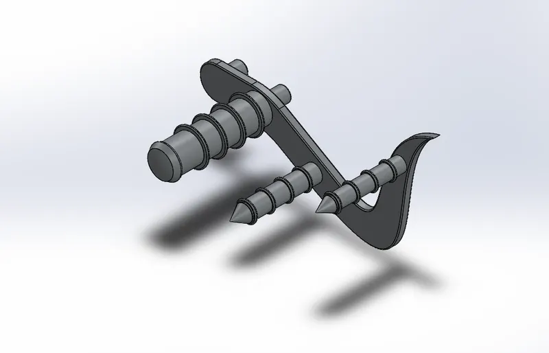
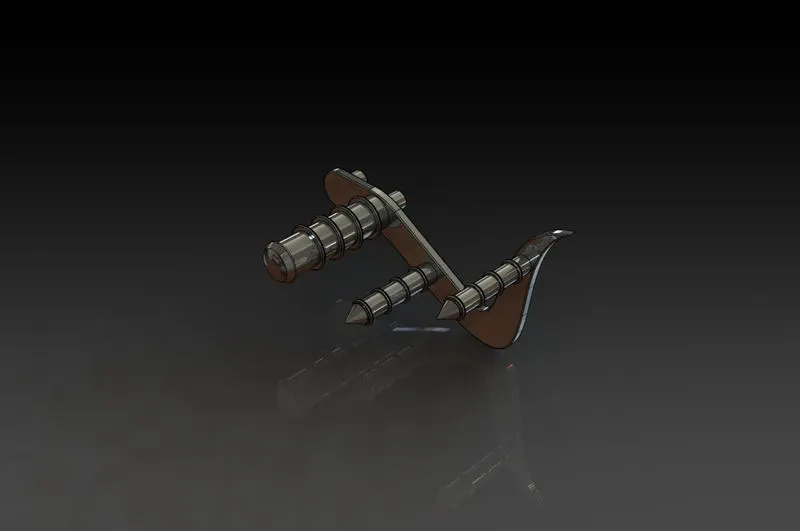
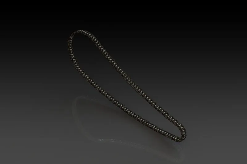
6.Chain- Chain used to transfer power from engine to rear wheel which allow bike to move forward. Feature used in chain are-
- Extrude Boss
- Fillet
- Curved Pattern
- Mirror
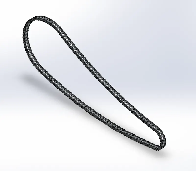
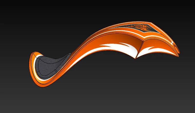
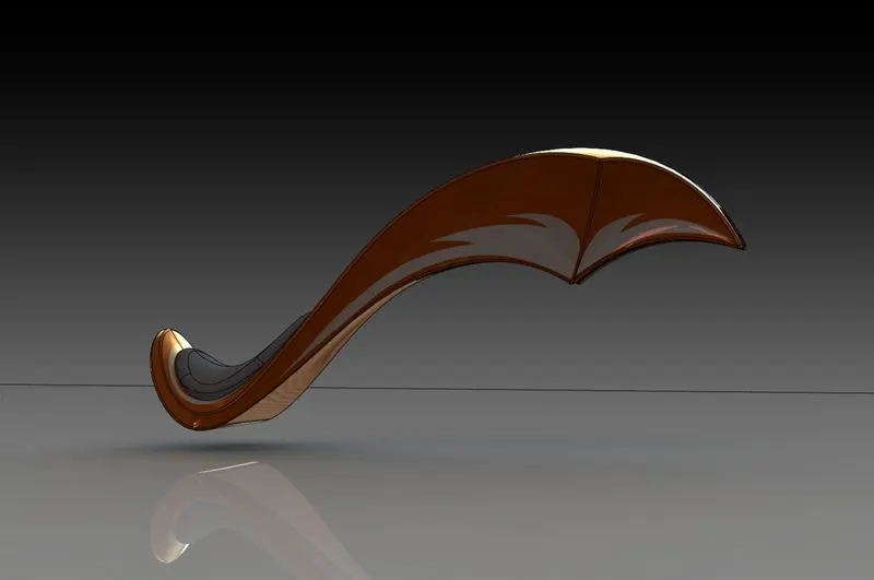
7.Fuel Tank – It is ignition fluid storage component like gasoline fluid. Fuel is transfer to engine where it gets ignited the feature used for fuel tank are-
- Project curve
- Boundary surface
- Knit surface
- Split line
- Surface trim
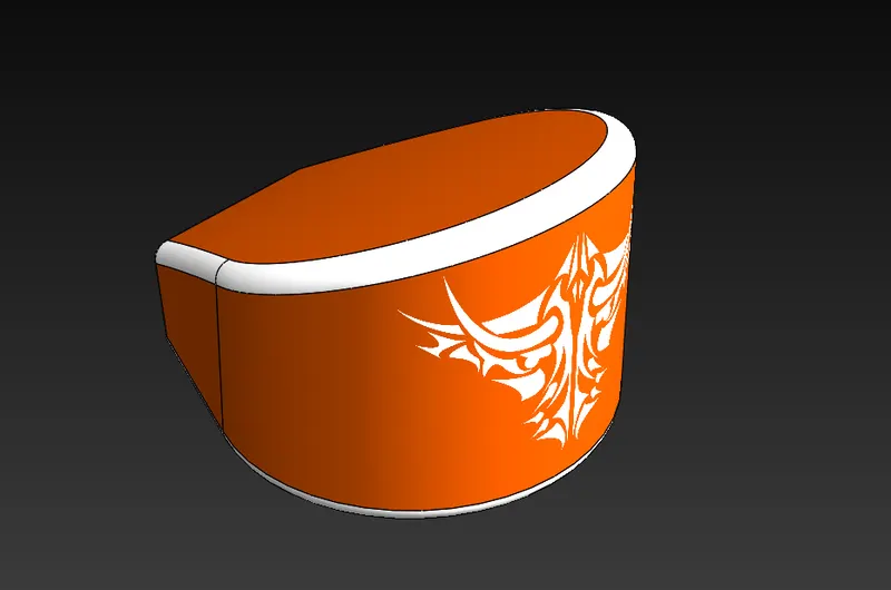
8.Oil Tank – As per its name oil tank used for storage of lubrication oil or braking oil also used for coolant purpose for engine component. The feature used for oil tank are-
- Extrude Boss
- Combine
- Shell
- Fillet
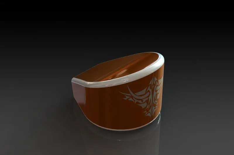
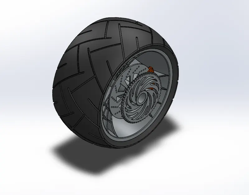
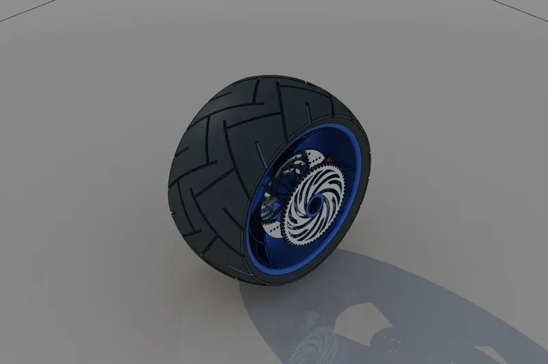
9.Rear wheel - Most important work of rear wheel is to support load and take power from engine to get forward motion of chopper. The feature is used for rear wheel are-
- Extrude Boss
- Revolve Boss
- Extrude Cut
- Fillet
- Circular Pattern
- Chamfer
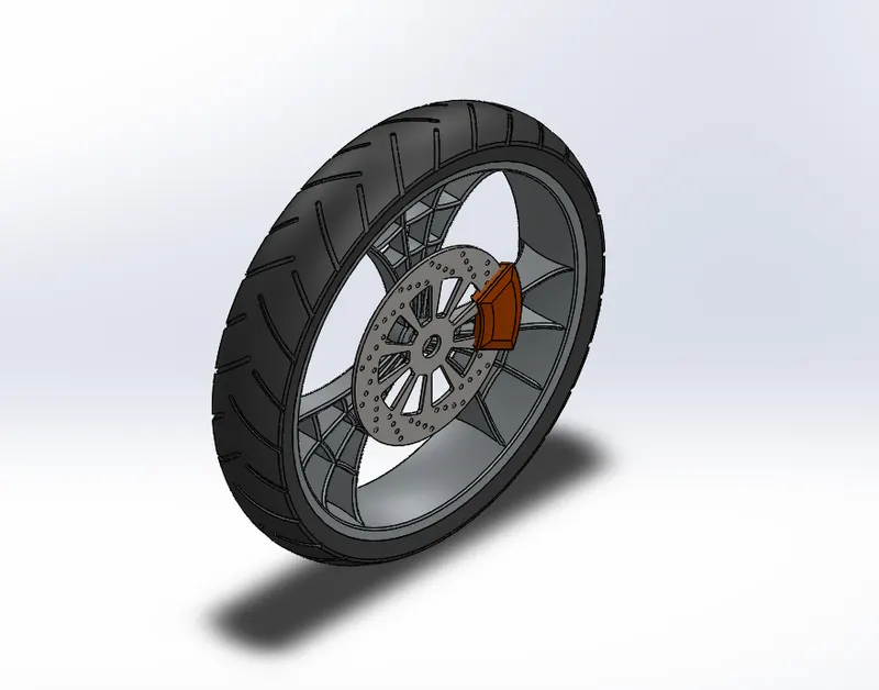
10.Front Wheel – Front wheel helps to take the front load of chopper and give the direction to chopper. Also move straight forward with help of rear wheel. The feature used for front wheel are-
- Extrude Boss
- Revolve Boss
- Extrude cut
- Circular Pattern
- Fillet
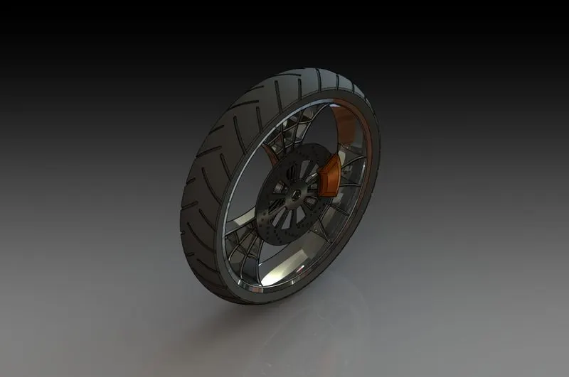
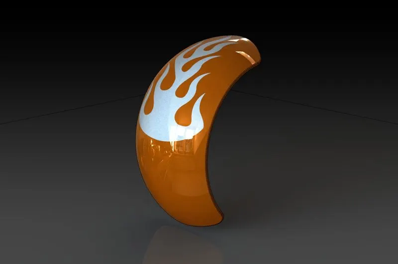
11.Front Fender – front fender used for the purpose to protect spreading of mud and rain water to chopper body. The feature used for front fender are-
- Revolve body
- Split body
- Fillet
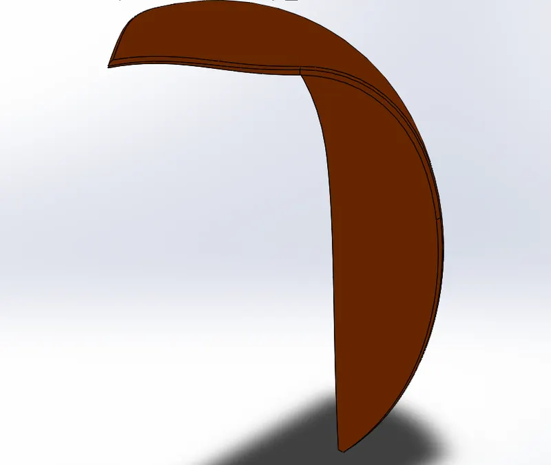
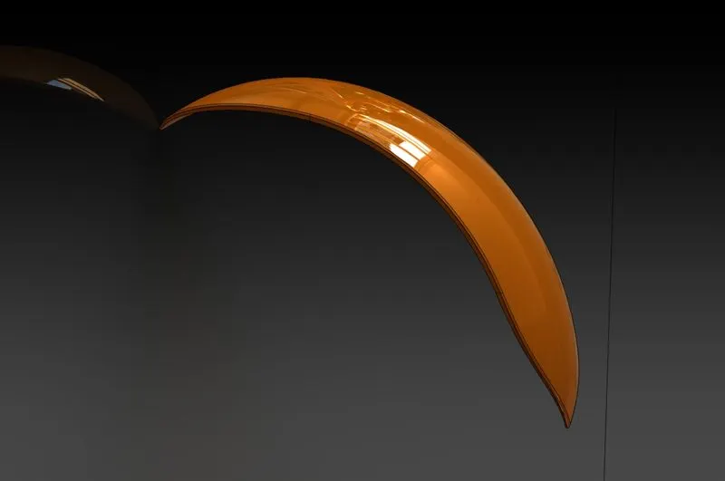
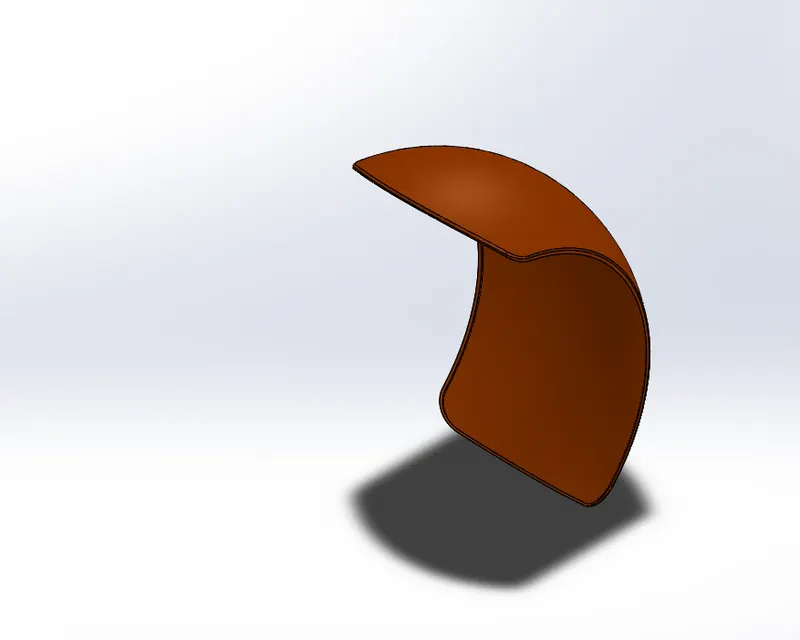
12.Rear Fender - As like Rear fender it is also used to protect the chopper from mud and spreading water and driver also. The feature used for front fender are-
- Revolve body
- Split
- Fillet
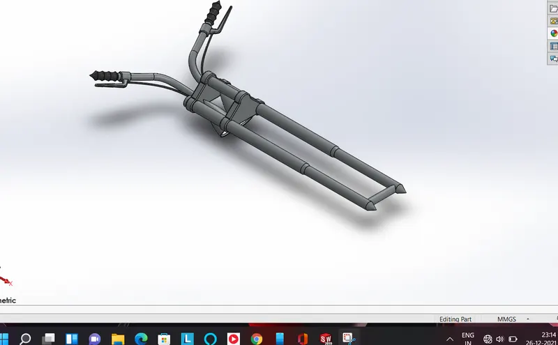
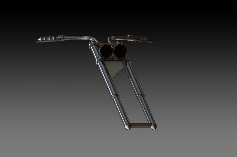
13.Front Fork - Front Fork used to absorb the shock which generate due to driving chopper on the road and non-uniform path surface as well.Front fender is control unit of direction,break,lamp switches etc.The feature used for fork are –
- Extrude boss
- Revolve boss
- Swept boss
- Dome
- Mirror
- Fillet
- Combine
FINAL ASSEMBLY –There are two types of assembly environment
1.TOP-DOWN – In top down assembly we are creating and designing the all geometry part within assembly.
2.BOTTOM-UP – In bottom-up assembly we are creating and designing an individual geometry models and then assembled into assembly environment by calling and applying mates relations.
In American Chopper we use bottom-up assembly
In final assembly all components are assembled together with proper mates relation and surface relation.During assembly the chassis body kept as reference body.
PROJECTION METHOD –
1.First Angle- In which object is placed between projection plane and observer.so that we see front view and below that top view ,at left side of elevation get RHS view also.
2.Third Angle-In this method the object is placed behind projection plane .so we get first top view and below that front view,at right side of elevation get RHS view.
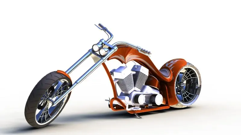
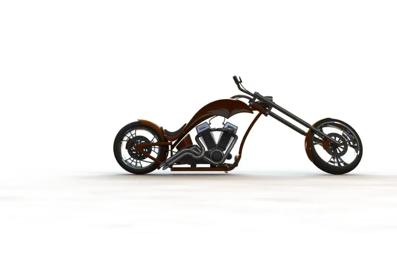
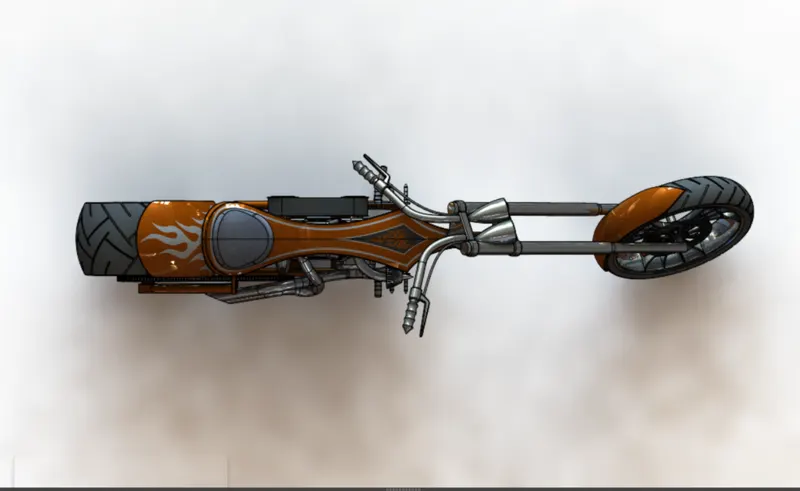
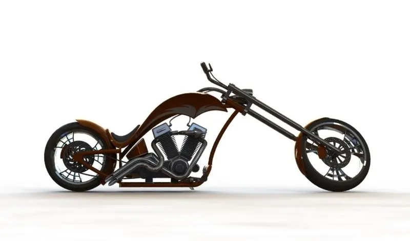
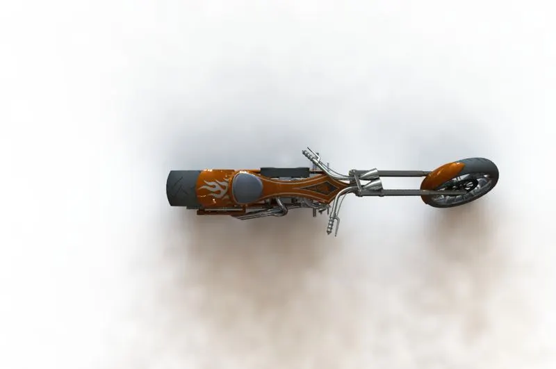
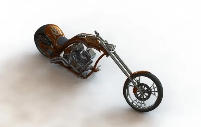
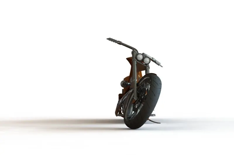
FINAL ASSEMBLY MULTIPLE VIEWS
1.FRONT VIEW
2.TOP VIEW
3.ISOMETRIC VIEW
4.RHS VIEW
5.LHS VIEW
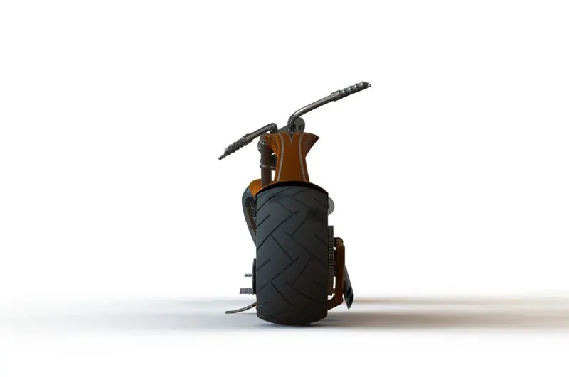
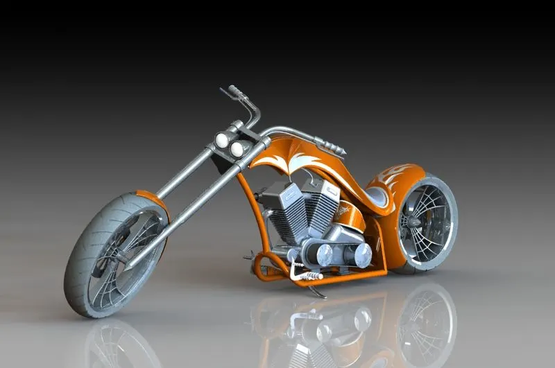
RENDERING VIEW OF AMERICAN CHOPPER WITH REFLECTING BLACK STUDIO SCENE
1.FRONT VIEW
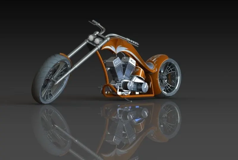
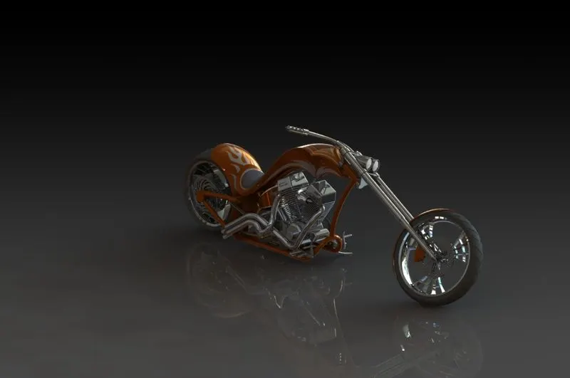
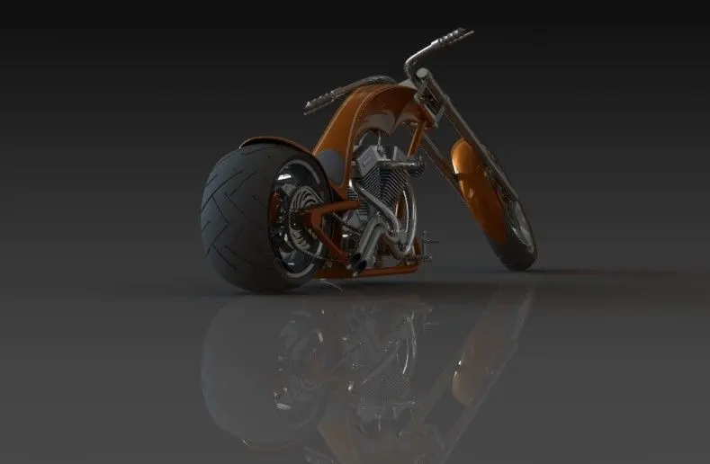
CAMERA SETUP VIEW
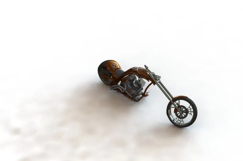
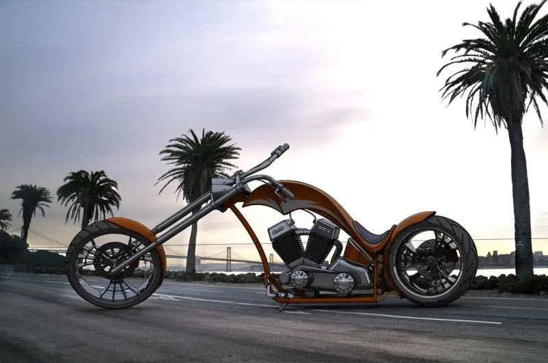
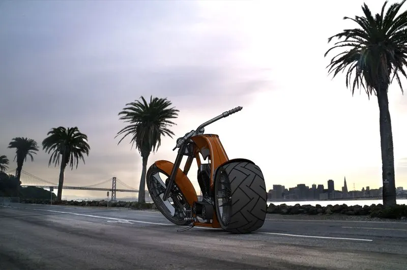
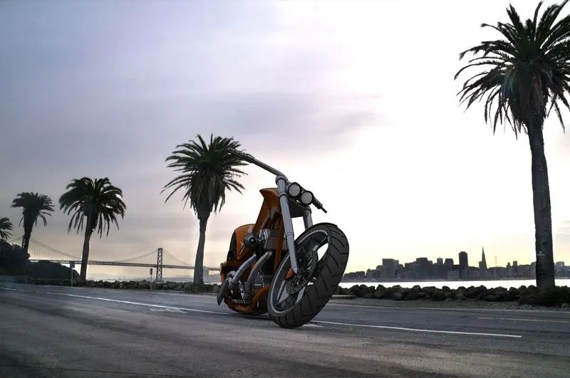
AMERICAN CHOPPER RENDER WITH BACKGROUND VIEW
CONCLUSION-
Solid work is very handy software in which we can create 3D model fast and easy way.rendering in solid work is very effective tool which gives a nice realistic view for model.
American chopper have very powerful engine and all components are metallic categoryand as the ponit of view of design and modeling of compicated components which help to understand uses of feature like appearance,material,feature tool in solid work.