Week 9 - Project 1 - Door Applique Design with Engineering Features
DOOR APPLIQUE DESIGN
OBJECTIVE:
- Analysing the class A surface given as input.
- Create the tooling axis .
- Create the B surface for the given class A surface.
- Create the C surface with the help of class A surface.
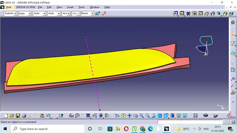
- Creating the solid closed component with the help of closed surface based feature.
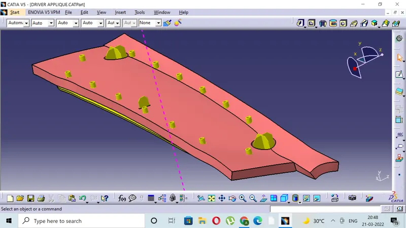
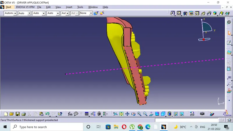
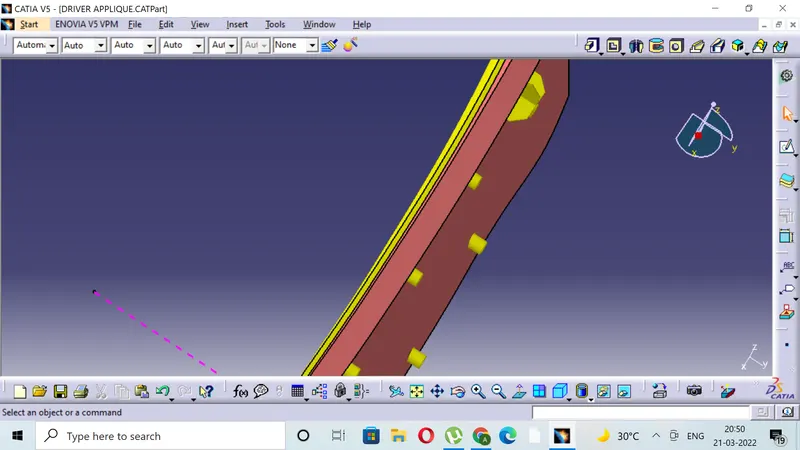
- Creating the LOCATORS and HEAT STAKES on the part.
- Checking all the design rules for LOCATORS AND HEAT STAKES creation.
- Draft analysis of class A and whole component.
- CLASS A SURFACE
The class A surface is the surface created from the concept sketch in the software called AutoDesk ALIAS, the class A surface is basically the styling surface and it is used as reference by the product designer to design the component with the help of tooling axis and draft analysis, here we have applique as a class A surface.
3 . TOOLING AXIS CREATION
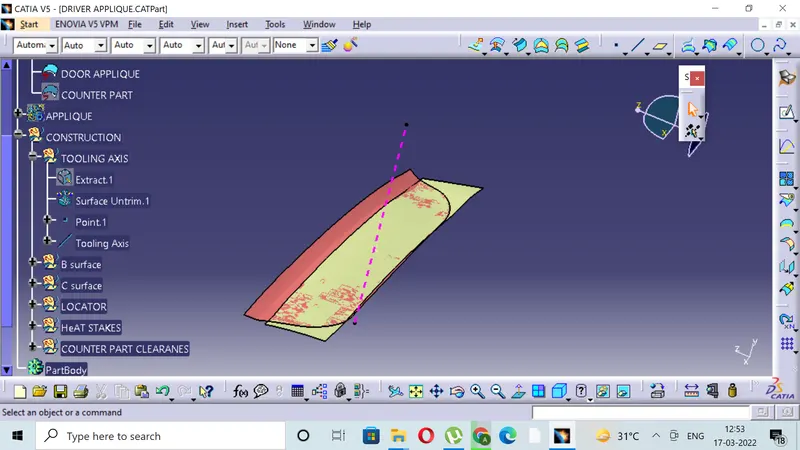
- Tooling axis plays important role in plastic product manufacturing and designing, this axis decides the direction in which mould is going to work while production of the component.
- The main focus while deciding the tooling axis is clearing the component in the moulding in the same axis with the minimum use of the side core for producing the component, the side core usually adds up to the cost of the component.
- For the particular component X,Y and Z can be the possible direction for the tooling axis.
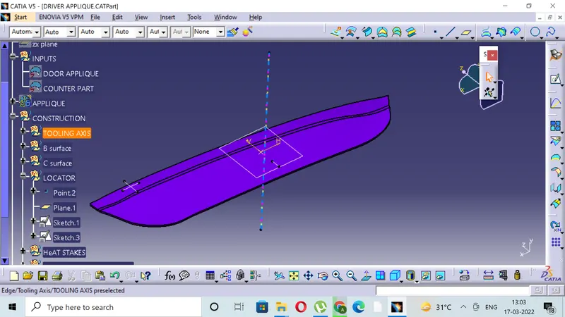
- You must specify the axis system by creating the point on the surface.
- With the help of the intersect in the YZ plane create the tooling axis in YZ plane .
- With the help of the intersect in the ZX plane create the tooling axis in ZX plane.
- The last step is to bisect the two tooling axis to obtain the main tooling axis of the class A surface.
- Here the component is flat with 0 draft angle so line perpendicular to centre is tooling axis .
4.CREATING THE B SURFACE
- The B surface is the surface where all the necessary attachments and supports are made for the component.
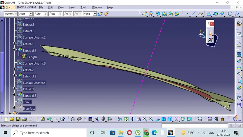
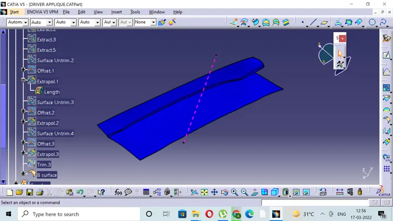
- The B surface is created using the class A as reference and extracting the major surfaces without the edge fillets.
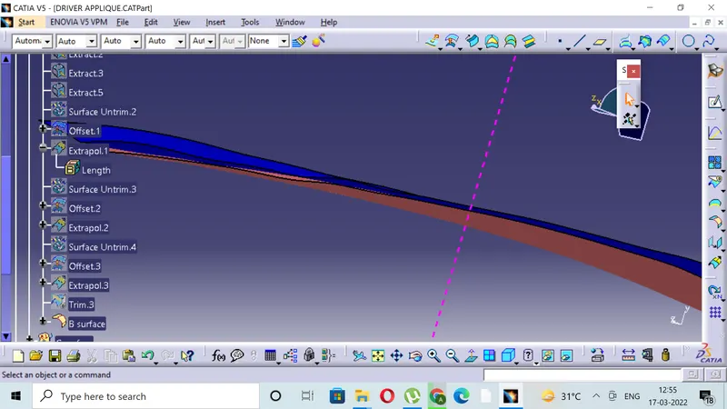
- The extracted surfaces are then extrapolated to get the better view for trim,then offset these surfaces to the thickness of the component and then trimming the surfaces to get the B surface.
- The necessary trimmed surface must contain the edge fillets as class A surface.
- The edge fillets provided to B surface must be given properly to maintin the constant thickness throughout the component so as to avoid the flow line defects.
5)CREATING THE C SURFACE
- The C surface is the surface which is responsible for providing the thickness to the component.
- The C surface is the intermediate between the class A and class B surfaces.
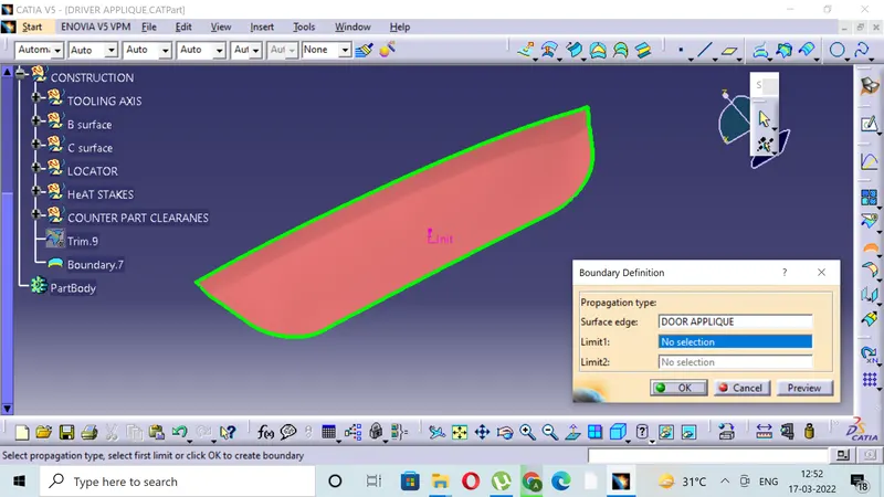
- The C surface is created by extracting the class A with a boundary .
- Then sweeping it with minimum 3 degress of draft.
- Trimming extrapolating to get the final trim or join of the class A ,class B, and class C.
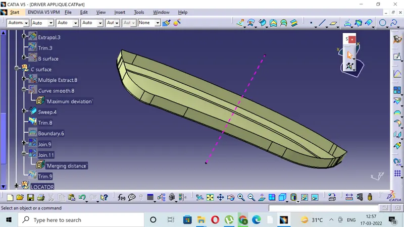
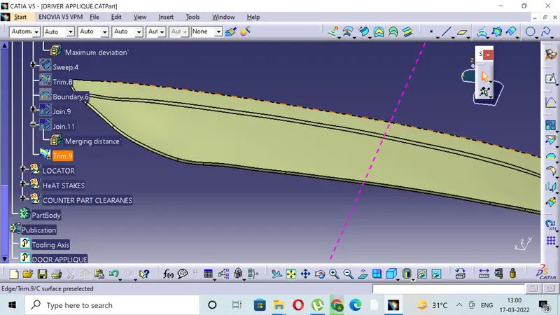
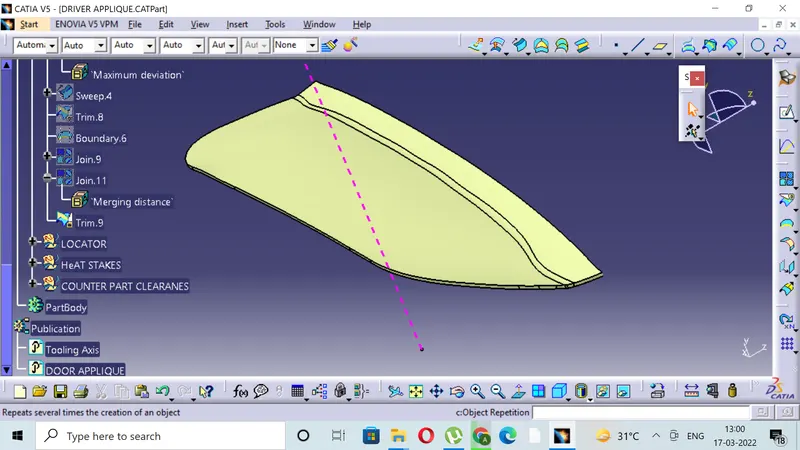
6)CREATING THE CLOSE BODY
- Create the closed body in part window of the catia .
- This feature is available in the surface based feature command in part window.
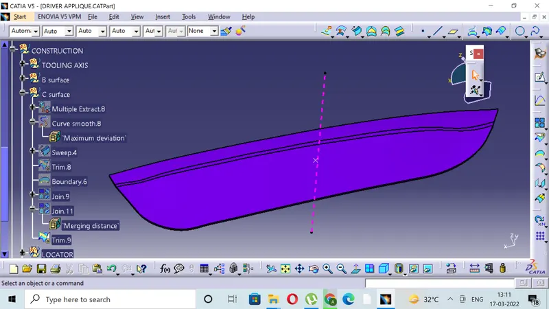
7)CREATING THE LOCATORS.
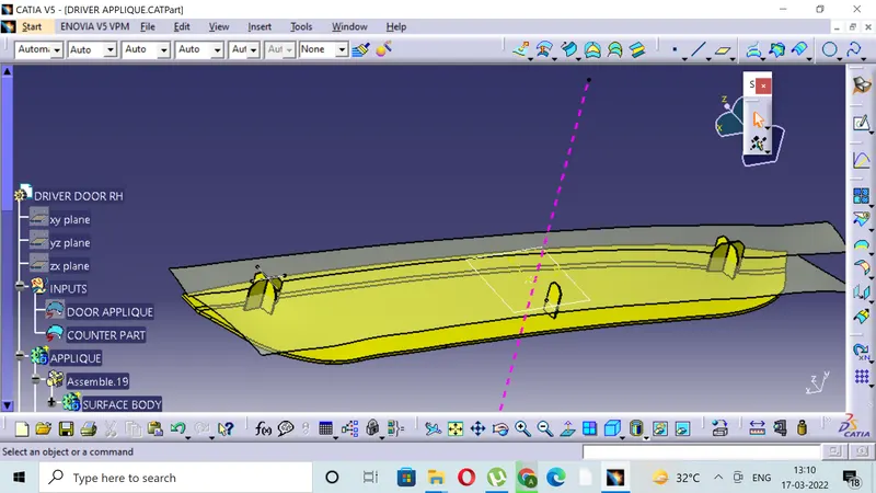
- Draw the position sketch for the locator .
- Create two 4 WAY locators by paste special and translating it to the y direction.
- Create 2 WAY locator at the center.
- The distance of all the locators with the B surface should be similar still (0.1mm -0.5mm ) of distortion is acceptable.
8)CREATING THE HEAT STAKES.
- Create the single heat stake following the design rule of the screw boss.
- Now using extract and boudary command and following the parallel curve create the points around for the heat stakes.
- Position the heat stakes at different points.
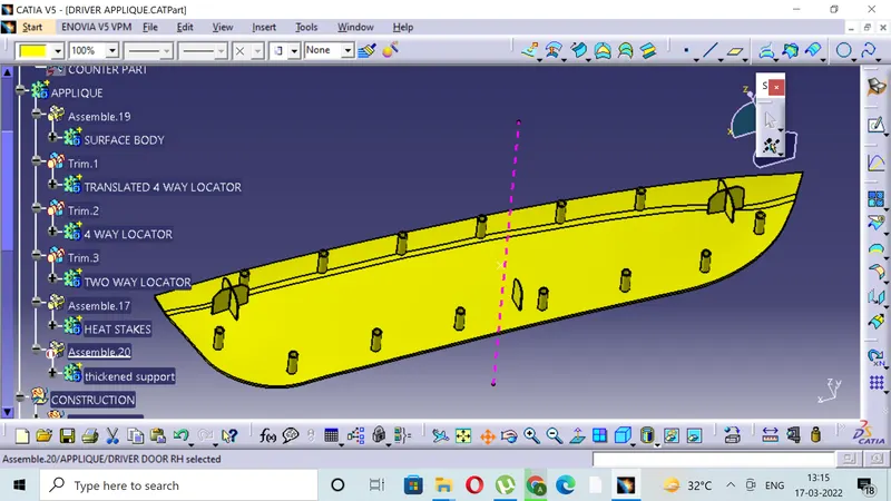
9)Thickening the support given and providing holes for the locators and heat stakes.
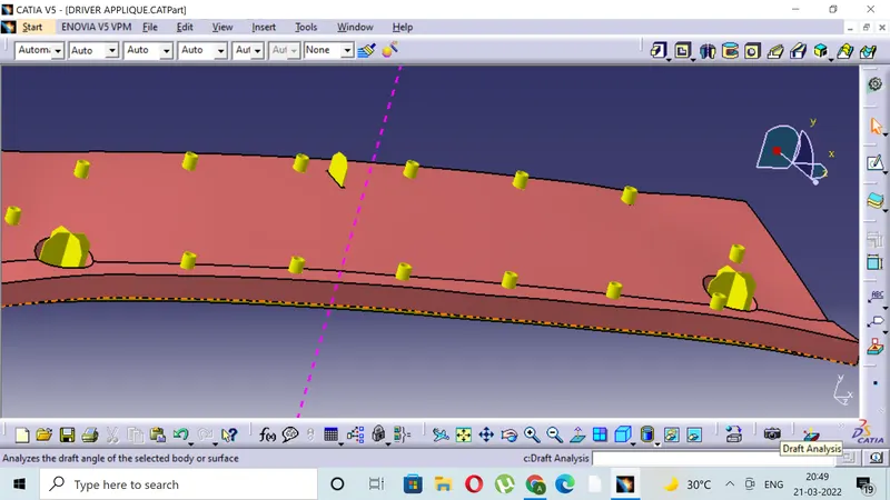
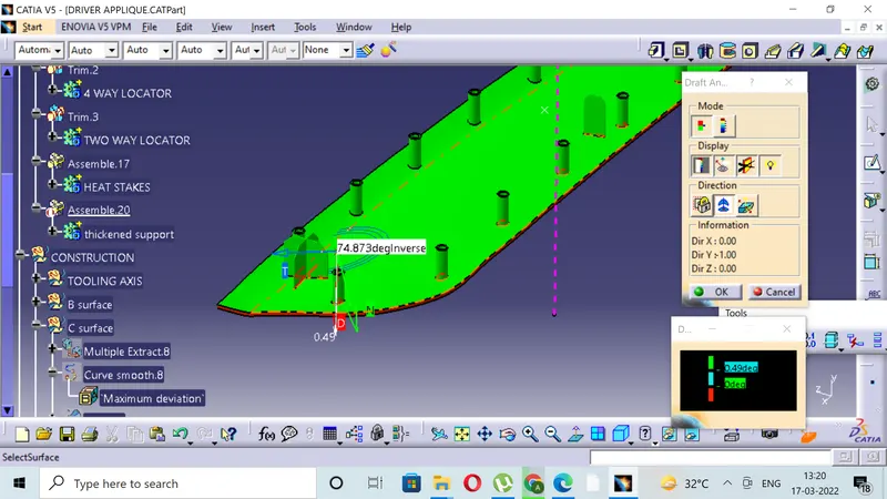
10)DRAFT ANALYSIS
- DRAFT ANALYSIS OF THE HEAT STAKES AND LOCATORS:
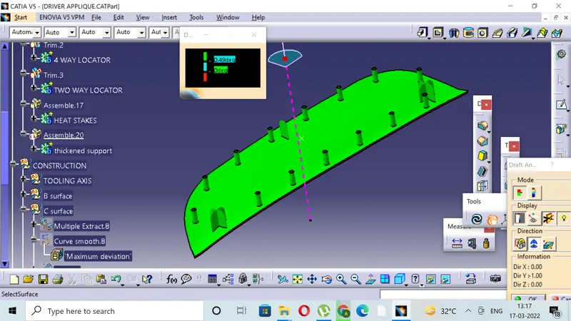
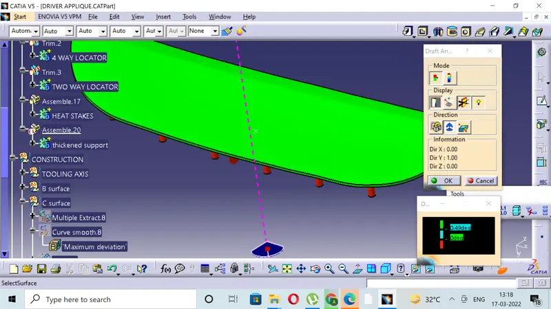
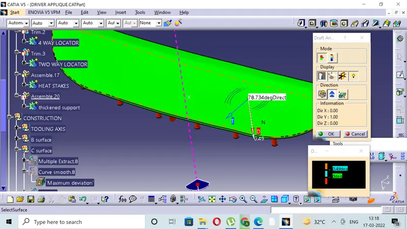
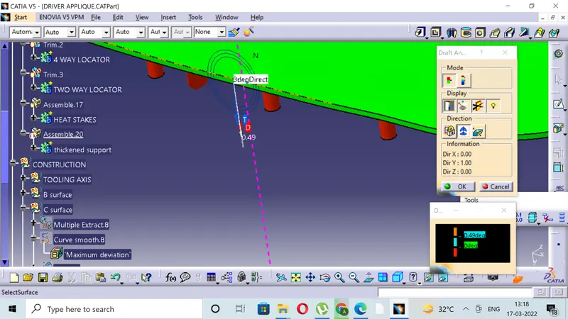
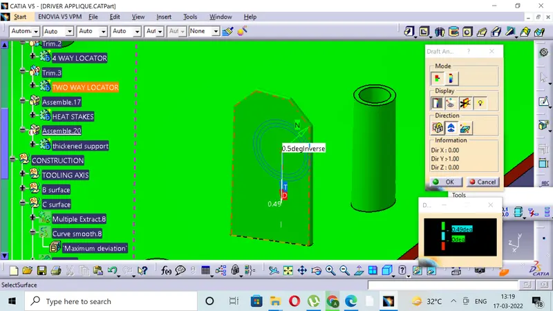
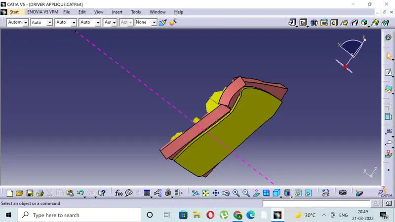
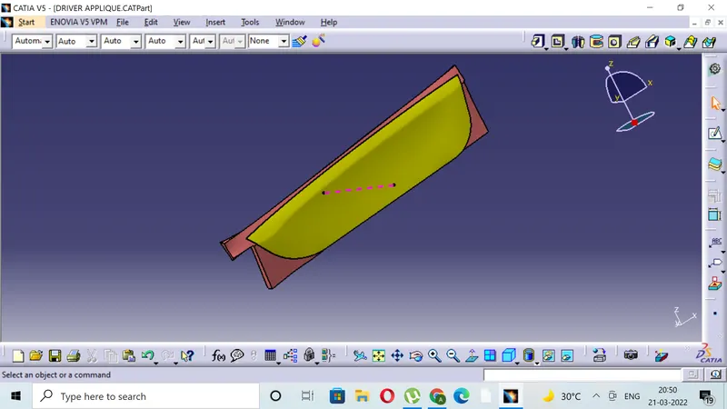
DRAFT ANALYSIS OF THE COMPONENT AS WHOLE
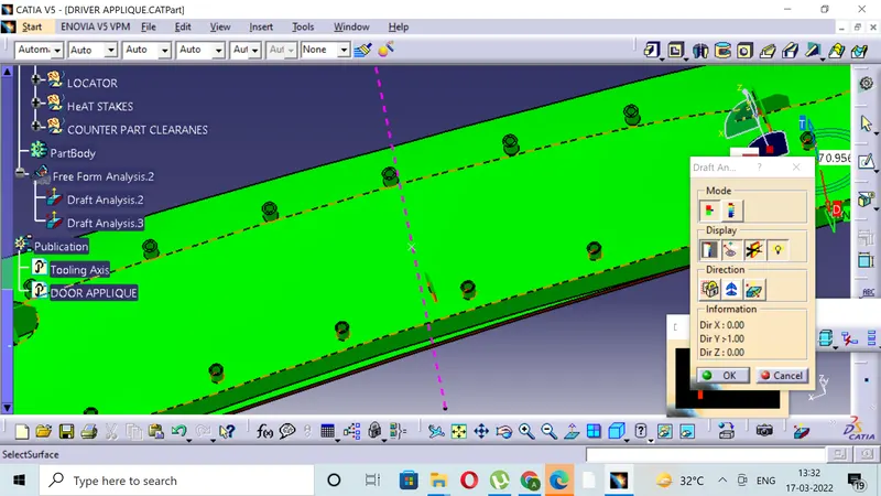
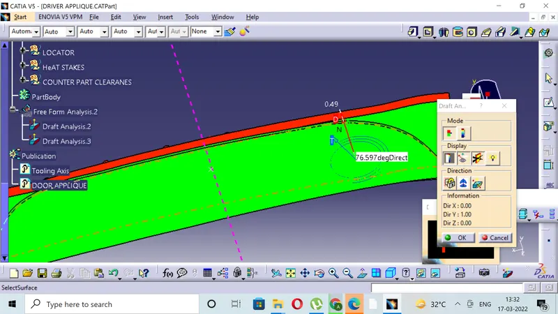
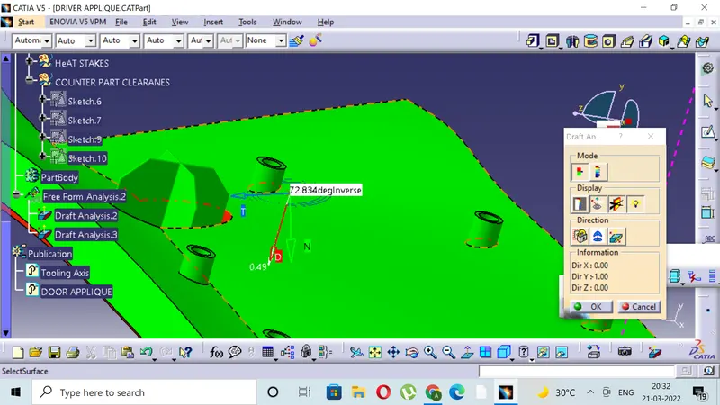

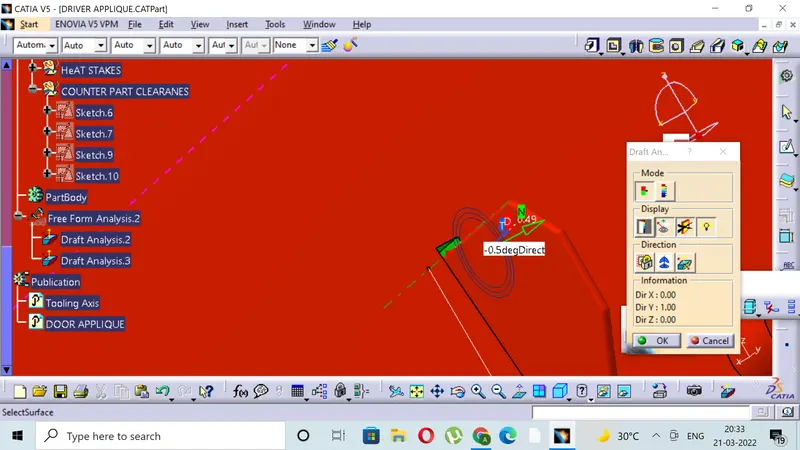
VIEW IN ALL ASPECTS: