Week 9 - Project 1 - Door Applique Design with Engineering Features
Aim:
To create plastic design,attach the engineering features and generate draft analysis for door applique class A model
Objective:
To create tooling axis and perform draft analysis on given Class A surface
To create class B and Class C surfaces based on the given class A surface
To create engineering attchment features such as Locators and Heat stakes.
To assemble features to main body of door applique.
To perform draft analysis on final assembly
To create the part body of door panel and create clearances for attachment features in it.
Design methodology:
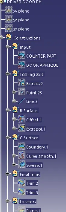
we need to create an tooling axis by using bisection method but in this case we can find the tooling axis simply by looking at class A surface. here we can ssume axis normal to the top surface passing through center point of surface as tooling axis
The prefernce of choosing the tooling axis would be line normal to large flat face or through hole element in the part.
Select the base surface from the class A surface and extract it.
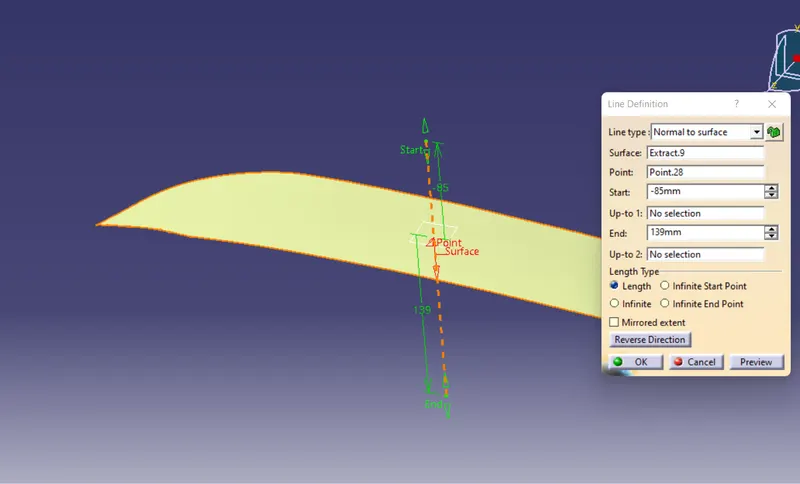
create a point on this surface In point definition give over the surface as first reference and select the extracted surface in dimension text box give 0 as the value . this by default will create a point in centre of surface.
Create a line with point as first refernce and extracted surface as the second reference.
The created line is our tooling axis
Class B surface:
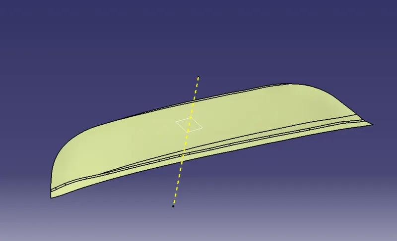
this is similar with difference as class b surface contains provisions like stiffiners screw bosses ribs and other support features. this surface is other side of product which will be hidden from plain sight.
This surface is created by offseting the class A surface to 2.5mm which is thickness of final body
Class C Surface:
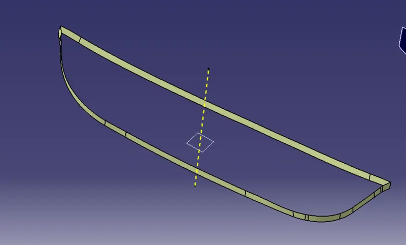
Using boundary option on class A surface boundary is created
for created boundary use smooth curve option now asweep the curve with draft angle of 3 deg use tooling axis as reference to sweep the surface.
Now all surfaces are created we trim the surfaces to create a closed surface . 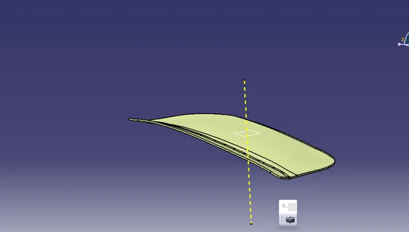
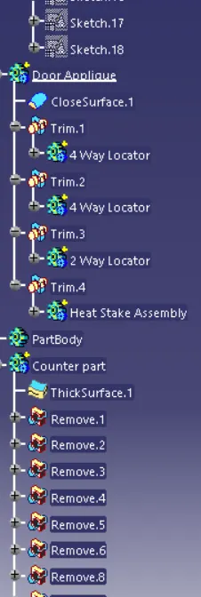
now close surface command is used to create solid model.
The draft is provided to solid model as we created it using the Class C surface.
Locators:
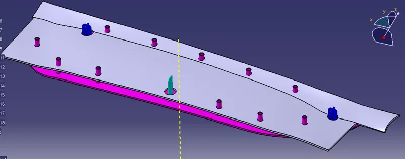
the locators are used to locate and guide the plastic part to assemble with vehicle enviorment parts . the locators also serve the function of restricting the degrees of freedom. they allow only one degree of freedom. here according 3-2-1 princple we used 2 4 way locators and one 2 way locator
Procedure for locators :
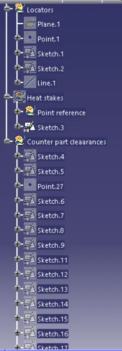
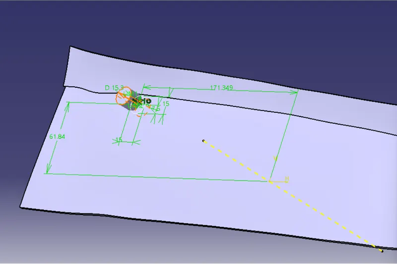
Create a point at the centre of the surface of door attachment by point definition
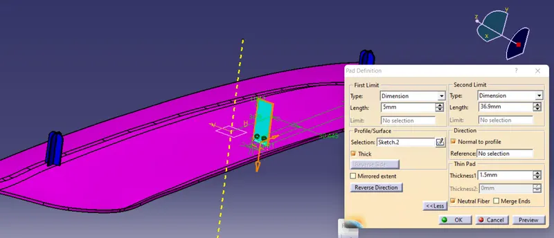
Create a plane on the surface at center by plane definiton with reference to a point which was created and then create a sketch of 4 locator on plane
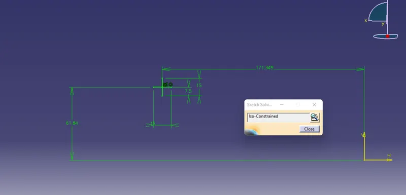
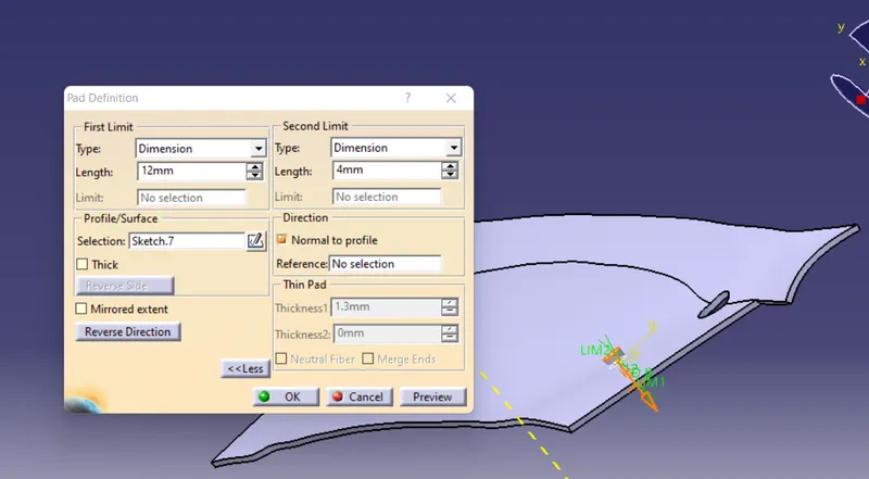
pad the sketch in part design using thick option and then click the more option and select neutral fibre and thickness 1 should be more than 40% of main wall thickness
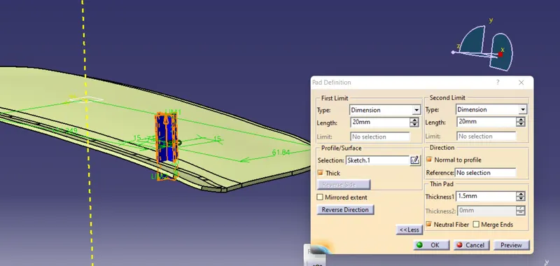
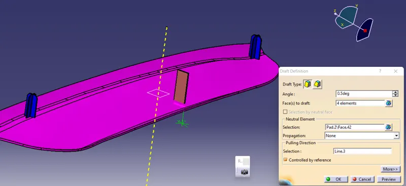
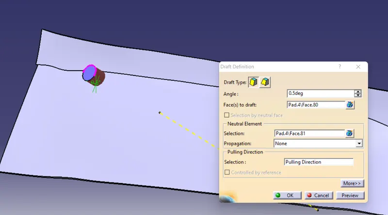
Draft face of the padded area by faces to draft - select the faces to draft , neutral elemnt selection -select the base surface and pulling direction - tooling axis.
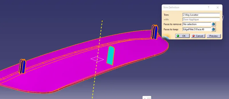
After drafting the faces chamfer edges at the top and fillet the edges and faces .
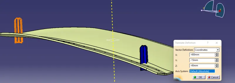
Copy the part of 4way locator and paste it with reference link and translate it to other side by coordinates
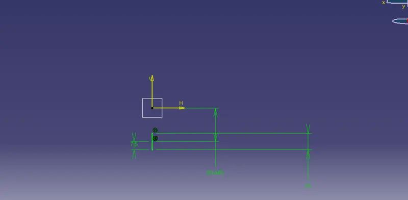
Now create a 2 way locator at below the centre by creating a sketch and do the same process of padding drafting and filleting
Heat stakes:
the plastic components are assembled with sheet metal parts of vehicle by heat staking , akind of plastic welding. the protruding cyclinders are heated and pressed agaisnt the sheet metal to make a weld . the protruding cyclindrical shape extensions are called heat stakes.
Procedure for heat stakes:
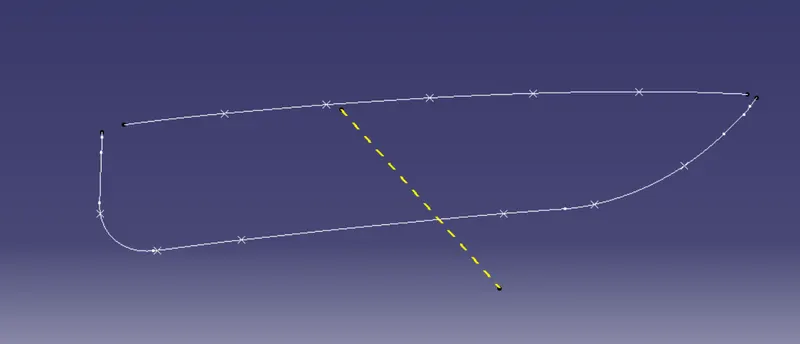
Offset the class A surface to 2.5mm and extract the boundaries by parallel curve to offseted surface
parallel curve - extracted boundaries by parallel curve definition curve- extracted boiundary ,support -surface , constantg - distance.
Give points repetition to parallel curves by points and planes repetition by curve parallel curve parameters- instances-no of points , No heat stakes should be present nearer to locators.
Now create a sketch on a point created on a parallel curve .draw the circle with diameters of 5mm and 7mm and in part design and pad it .
type- to surface , limit - select class A surface.
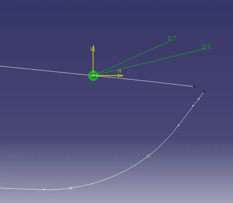
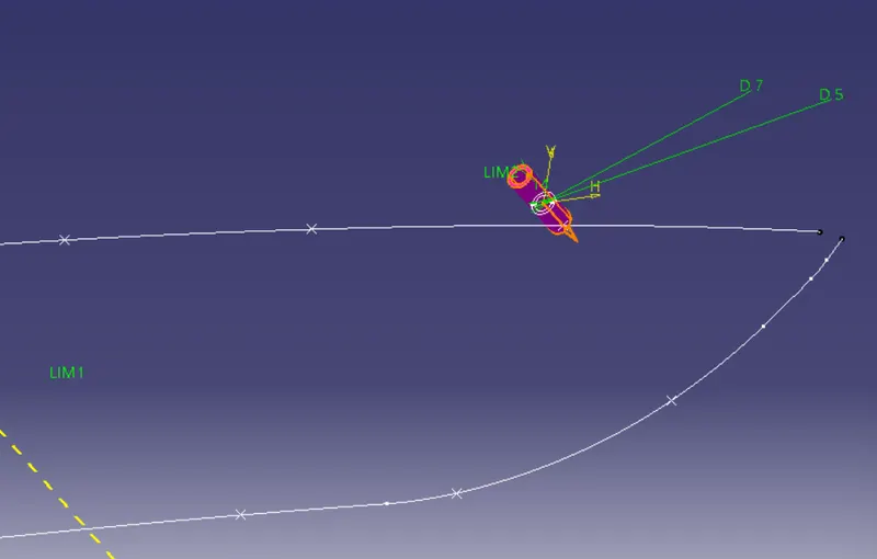
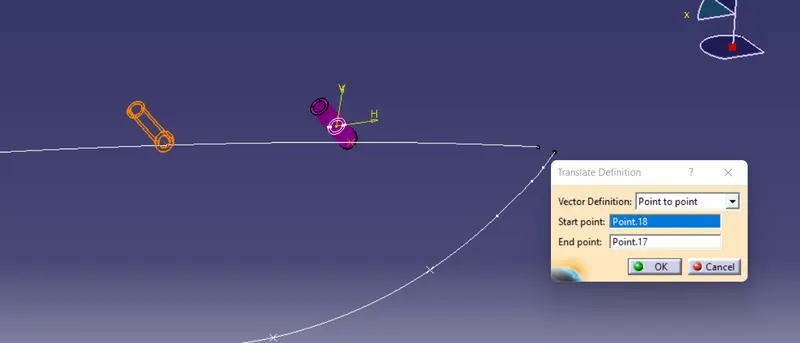
Copy the part body of heat stake and paste it special with reference link and then replicate points wgich are created by translate option. Vector definition -point -point .Translate the part body to heat stake to other point which was copied by selecting startand end points.
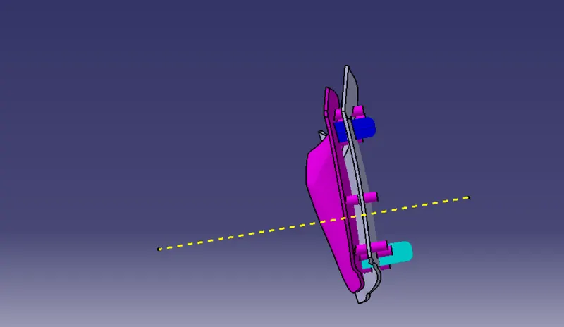
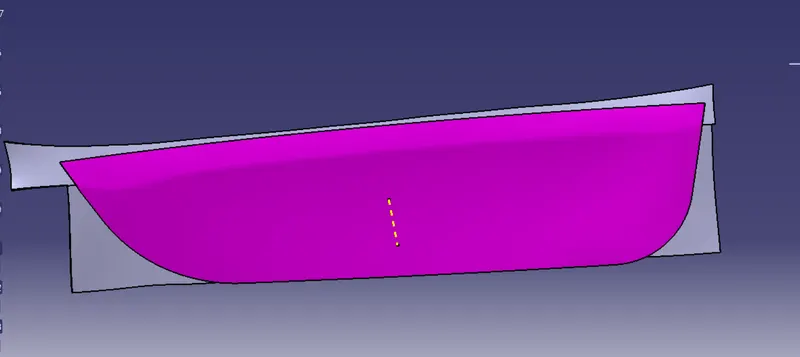
By Boolean operation assemble all the heat stakes part bodies in a single body and then untrim the heat stakes with solid body of door applique by selecting faces to keep. the distance between the tip surface of locator and door attachment surface should be equal for all locators also the height of heat stake should be smaller than locators.
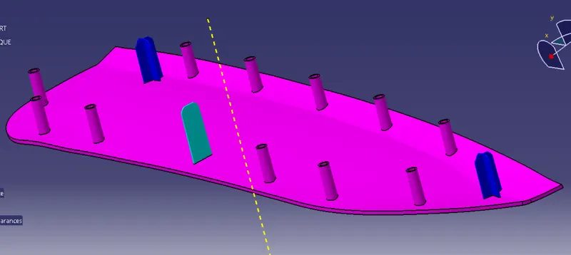
Clearances For Locators and Heat stakes on Door Attcahment surface:
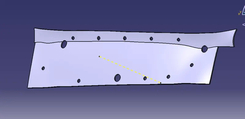
Thicken the door attachment surface by using thick surface in part design to 2.5mm thickness.
Now from locators sketch sopy the sketch in a new geeometrical set and then draw a circle of 8mm for clearences
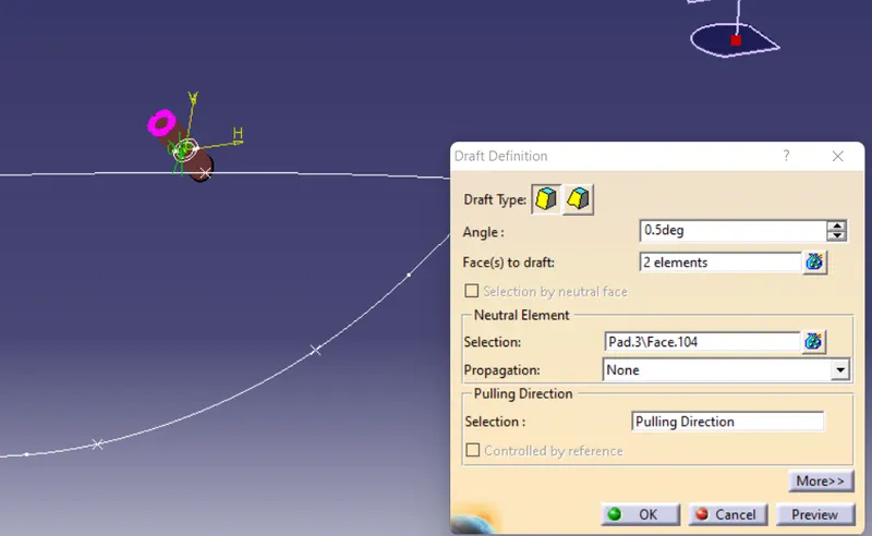
Pad the circle to an offset distance below the door attachment surface and draft to 0.5 deg.
By boolean operation remove the pad from thicken surface so the clearance gap between locator wall and clearence wall should be 0.1mmto lock motion .
Do the same process for remaining locators and heat stakes by creating the clearance gaps where the clearance gaps for heat stake should be 0.5mm
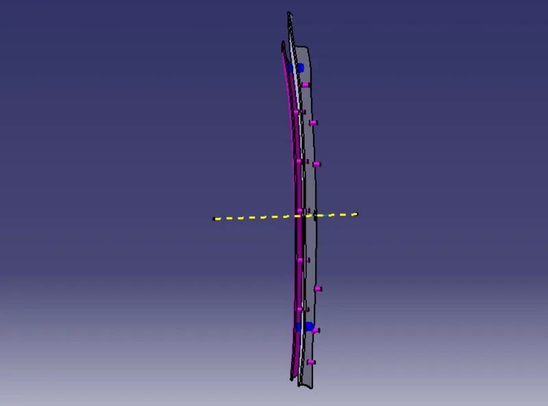
DRAFT ANALYSIS(Class A):
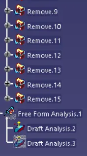
To perform draft analysis on the model: Go to menu bar > Analysis > Feature Draft analysis. to give draft direction use the compass and align Z-axis of it with tooling axis. Once it properly aligned , lock the draft direction. A red point shown on the screen ,select class A-surface and it will show us the current of the model . then go to display tab on draft analysis and select the first option under it colour scale and it will show draft value .set the value to 3 deg under the colour scale variat and press ok.here analysis can be done in two ways quick analysis and full anaysis we choose quick analysis.
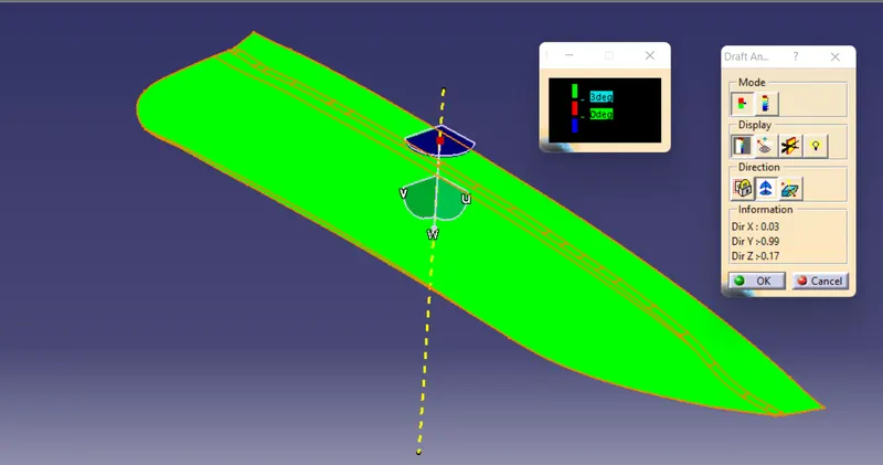
Here draft analysis shows
- The Green colour is drafted walls above 3 degree.
- The Red colour is drafted walls above 0 degree.
The analysis shows the drafted walls of Class A of door applique are above the par of 3deg which is permissible to manfacture in injection modeling.
DRAFT ANALYSIS(Complete body):
To perform draft analysis on the model: Go to menu bar > Analysis > Feature Draft analysis. to give draft direction use the compass and align Z-axis of it with tooling axis. Once it properly aligned , lock the draft direction. A red point shown on the screen ,select Closed complete body and it will show us the current of the model . then go to display tab on draft analysis and select the first option under it colour scale and it will show draft value .set the value to 0.48deg under the colour scale variat and press ok.here analysis can be done in two ways quick analysis and full anaysis we choose quick analysis.
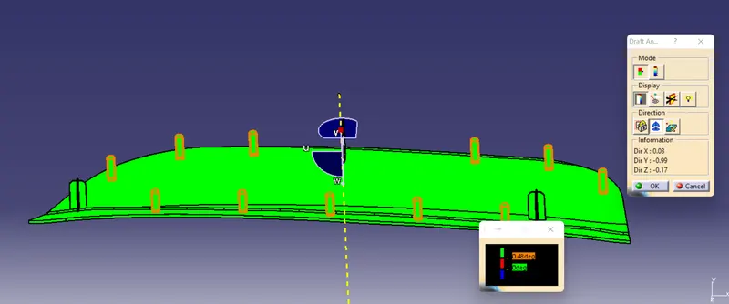
Here draft analysis shows
- The Green colour is drafted walls above 0.48 degree.
- The Red colour is drafted walls above 0 degree.
The analysis shows the drafted walls of door applique are above the par of 0.48deg which is permissible to manfacture in injection modeling.