Week 9 - Project 1 - Door Applique Design with Engineering Features
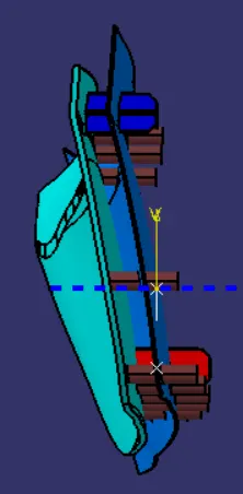
AIM: - Create the base bracket plastic component through the given class-A surface. To being with, the tooling axis for the given class-A surface should be created meeting the requirement of the draft angle and at the end perform the draft analysis on the model.
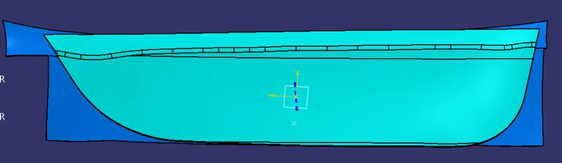
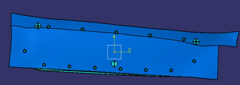
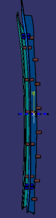
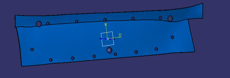
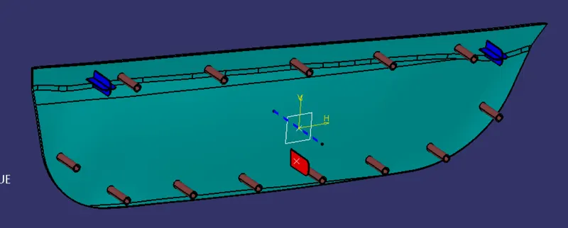
Create the heat stakes and the locaters considering the design rules mentioned in the video for the door applique.
THEORY: -
To locate a part to be machined and restrict its motion to accurately do the machining and constraint its motion 3-2-1 principle of location is used.
3-2-1 PRINCIPLE: -
To completely specify the position in space of a three-dimensional object (such as the cube that’s shown), we refer to six coordinates:
- Translational position along the X-axis
- Translational position along the Y-axis
- Translational position along the Z-axis
- Rotational position about the X-axis
- Rotational position about the Y-axis
- Rotational position about the Z-axis
It is a 3-step process of introducing 3-2-1-point locators in a plane for the best support and constraint.
For example, let’s say we use 3 points at the bottom of the cube above, which restrict the translational motion along Z (Z+ and Z-)
Now we use 2 points from the Y+ the direction of the cube to restrict the translational motion along with Y (Y+ and Y-), rotational motion along with Z. this way two degrees of motion are restricted.
Finally, to restrict motion along the only remaining degree of freedom that is the translational motion along the X (X+ and X-) a single point is used along the X+ direction of the cube to restrict all the motion.
LOCATORS: -
To restrict the degree of freedom of a 3d plastic components locators used.
There are various types of locators but for this application, we will use the following:
4 WAY LOCATOR: -
A 4-way pin restrict 4 degrees of freedom along 2 axes.
2 WAY LOCATOR: -
A 2-way locating pin restrict motion along 1 axis ( or 2 degrees of freedom).
HEAT STAKES: -
Heat staking is a pulled heat process to join two or more parts out of which one at least is made of plastic. The process is to deform the plastic material using heat and force at a set process time. The bond is made by partially de-forming the plastic part to fix the other.
PROCEDURE: -
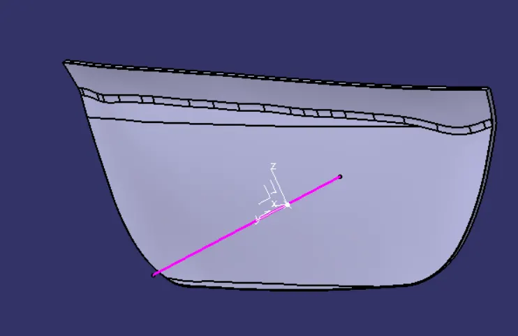
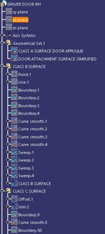
Create a point on the class A surface to move the main tool for component creation on the base surface.
Make an axis over the point created with the same direction’s ass the main axis.
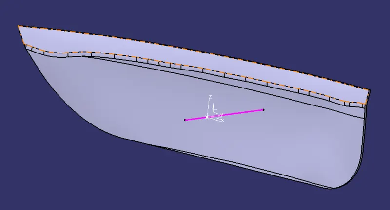
Using intersect command from generative shape design select the YZ plane as the first element and the class A surface as the second element.
After creating the intersecting lines select the line command and join the vertices which show the most possible draft angle manufacturable.
Bisect those two lines over the axis point we created.
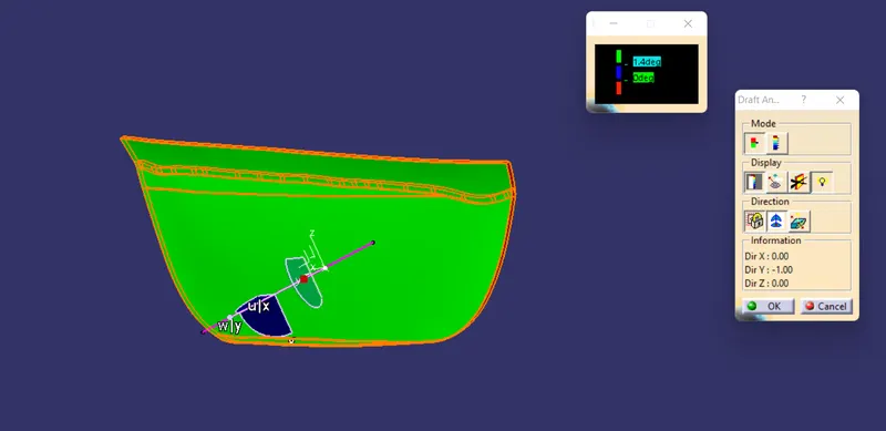
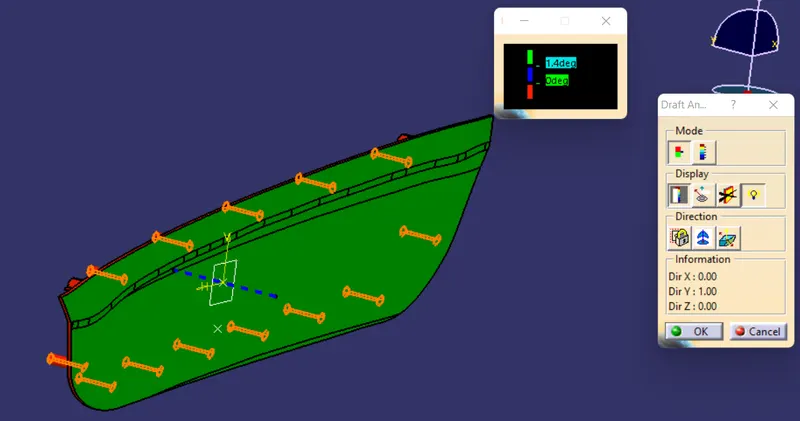
OBJECTIVE DRAFT ANALYSIS OF CLASS A SURFACE: -
Procedure: -
After tooling axis select the feature draft analysis option from the insert option.
Select the element to analyze.
Next click on use the compass to define the new current draft direction option and make it align with the tooling axis by dragging it to the axis.
If the color appears blue just click the invert option on the right side of the draft direction axis button.