Week 9 - Project 1 - Door Applique Design with Engineering Features
APPLIQUE DESIGN CHALLENGE
Creation of Tooling and CLASS B , C surfaces :
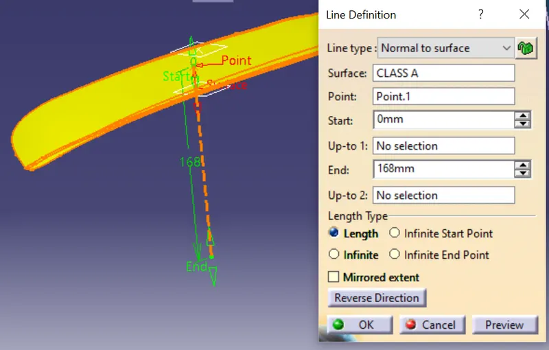
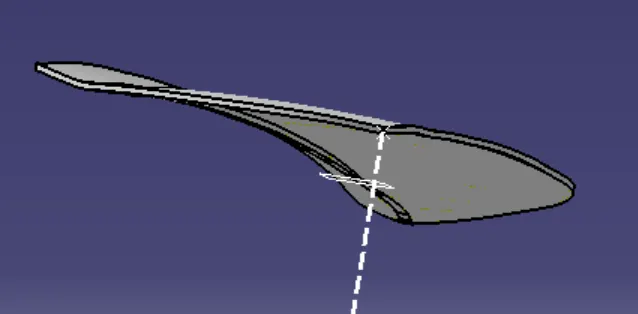
1) Initially create a point on the given CLASS A surface and then make a line perpendicular to the given CLASS A surface.
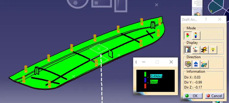
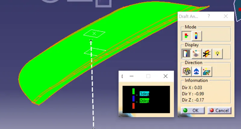
2) Perform draft analysis on the CLASS A surface to check the tool feasibility and for the given tooling direction all the surfaces should clear the tool.
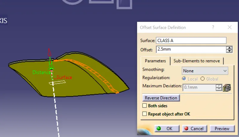
3) Now create the B side surface by OFFSETTING the CLASS A surface by 2.5 mm. Check the B surface thoroughly for any distortion or broken patches.
4) To construct the CLASS C surface use the SWEEP option and select the boundaries on the class A skin. Apply draft direction as tooling axis and then give a minimum draft of 3 degrees.
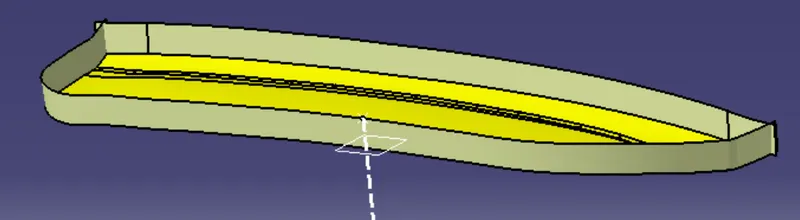
5) Trim the CLASS A and CLASS B surfaces with the CLASS C , then we can get a closed part.
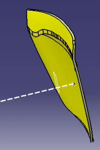
Creation of B SIDE FEATURES - 4 way locators, 2 way locators & Heat stakes :
LOCATORS :
1) As we have got a reference surface on which our applique will be attached to , we need to design our B SIDE locating features considering the attachment surface position.
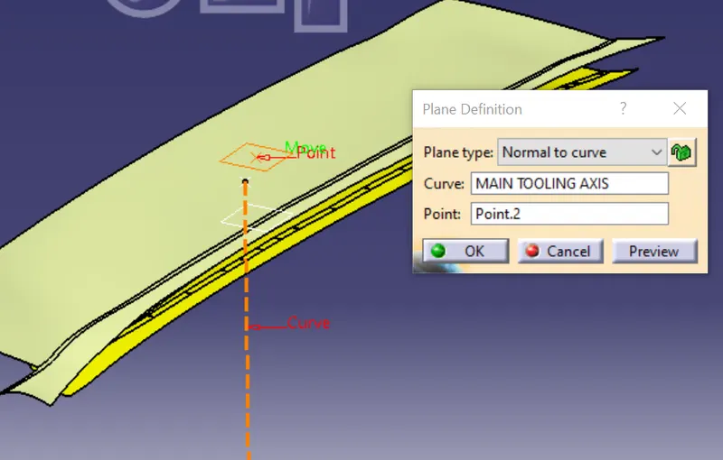
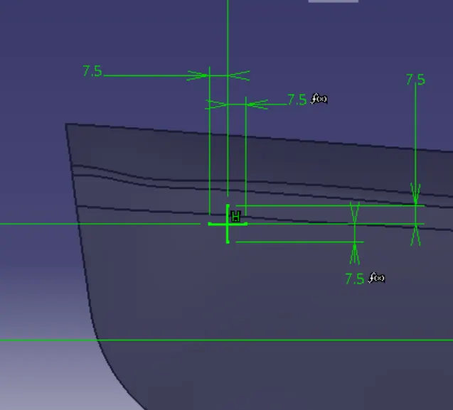
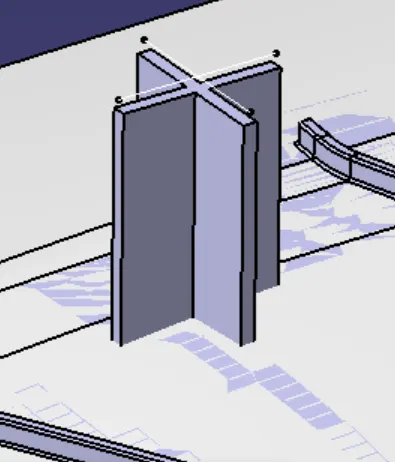
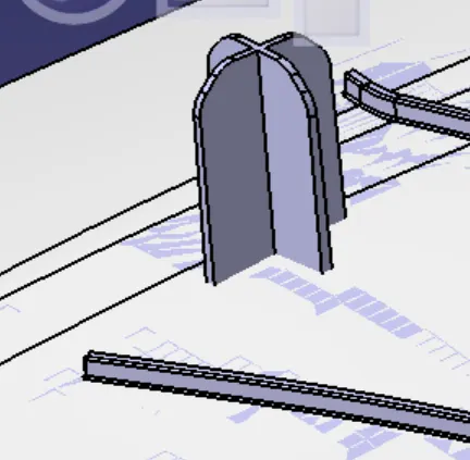
2) To create the 4 way locator make the sketch by making a plane using the reference surface. Make sure the plane is perpendicular to the tooling direction.
3) Extrude the sketch using thick option, the thickness of the B side feature should be 40% of nominal wall thickness.
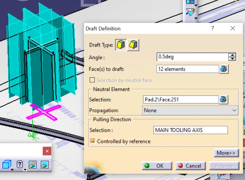
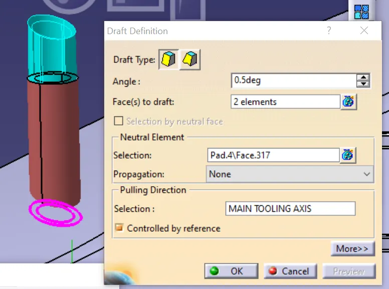
4) Apply a draft of 0.5 degrees on all the outer walls so that they can be cleared easily during ejection.
5) Apply chamfer on the 4 walls so that these locators can be easily positioned during entry.
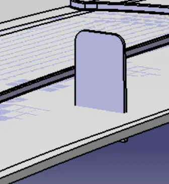
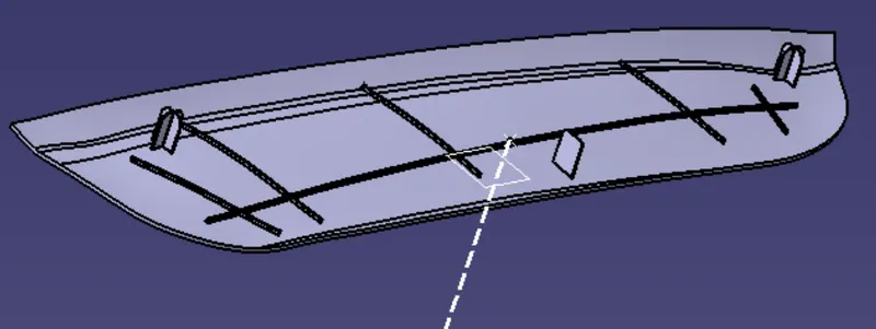
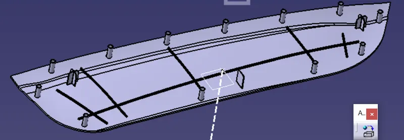
6) Similarly create the 2 way locators by making a sketch and extruding them. Once a locator is made we can move them by using coordinate translation based on the need and positioning requirement for the surface.
HEAT STAKES :
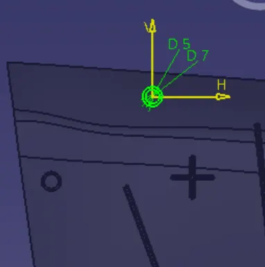
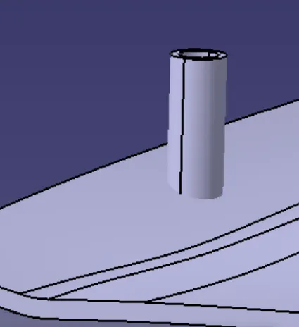
1) Now create a profile of two concentric circles on the sketch , make sure the thickness is 40% of the nominal wall thickness.
2) Extrude the profile and make sure they are long enough to trim with the main surface.
3) Apply draft of 0.5 degrees on the inner and outer wall along the tooling direction.
4) Make sure the height of locators is always higher than the heat stakes so that positioning happens first and then the heat staking process can be followed.
ATTACHEMENT SURFACE - ASSEMBLY HOLE CREATION :
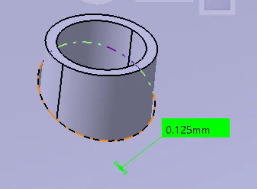
1) For fixing the applique we need to create proper assembly holes on the attachment surface so that locators can be positioned and then heat stakes can be inserted to fix them.
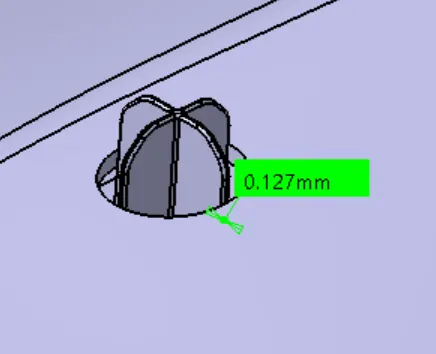
2) Maintain a maximum of 0.1mm gap with the hole so that the assembly is not too loose.
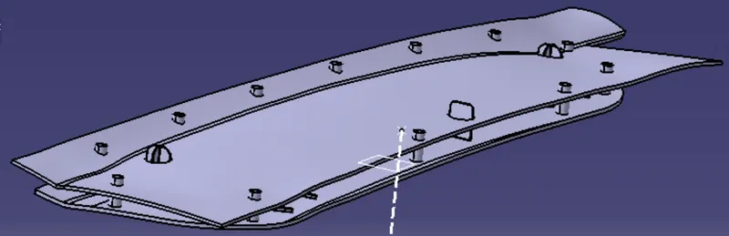
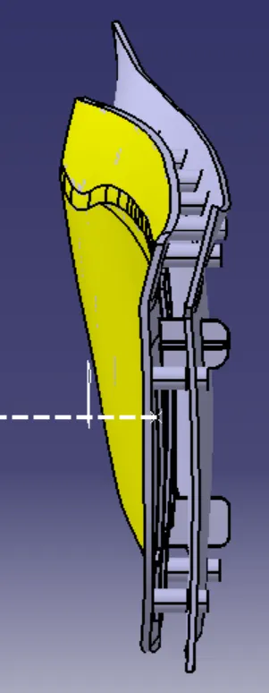
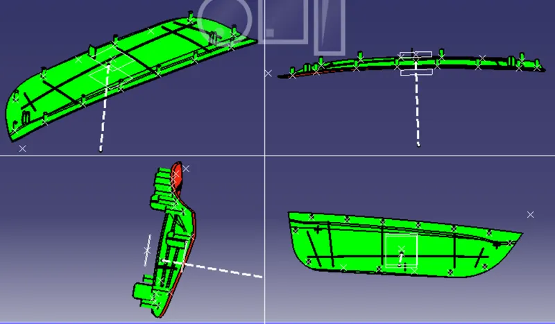
VARIOUS VIEWS OF THE COMPLETE MODEL :
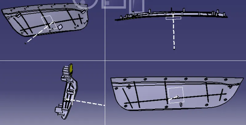
DRAFT ANALYSIS FOR THE B SIDE FEATURES :