Week 8 - Challenge 1 - Draft Analysis on a Fan Cover
DRAFT ANALYSIS OF FAN COVER
The following steps must be followed to ensure a easily understandable draft analysis,
1) CLASS A SURFACE - CHECK POINTS
- For the given class A surface , Join the surface and check if there is any opening between adjacent surfaces
- Select the surface and identify the number of closed boundaries by selecting the boundary option to make sure there is no undesired open surfaces.
- By performing the above two operations we have made sure there is no defect in the provided CLASS A surface.
2) CREATING TOOLING AXIS
- Observe the part and think about how to select a tooling direction on the basis of whether all the surfaces can be cleared with our chosen tooling axis.
- From observation we find that only if we make the tooling in Z direction it is possible to clear the hole. So we fix Z as our tooling direction.
- Initially, we make dummy tooling axis by making a line in Z direction using the centre point of hole as the origin.
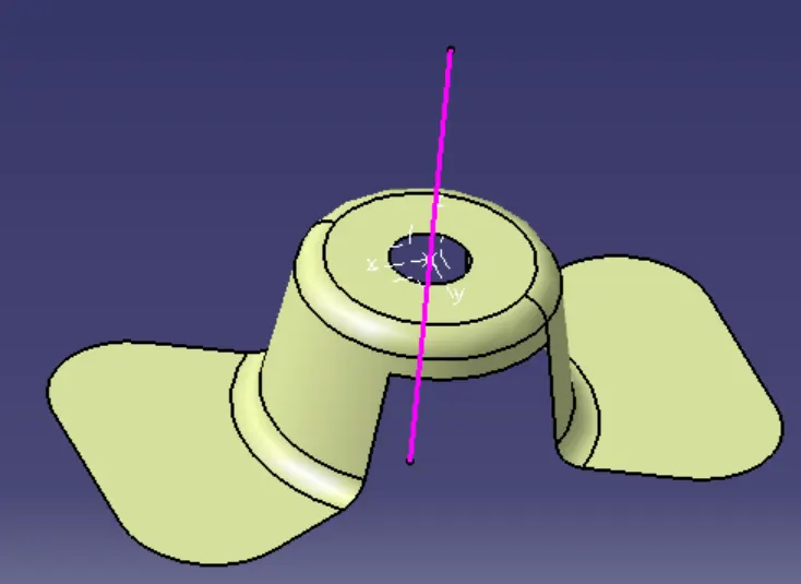
- Now lets analyse how the tool will clear the walls present in the X & Y direction.
- For the tooling in the X direction make lines that are parallel to the two side walls when viewed from the XZ plane.
- Now create a bisecting line to the two lines we created in the previous step. This will be our tooling that clears the X direction.
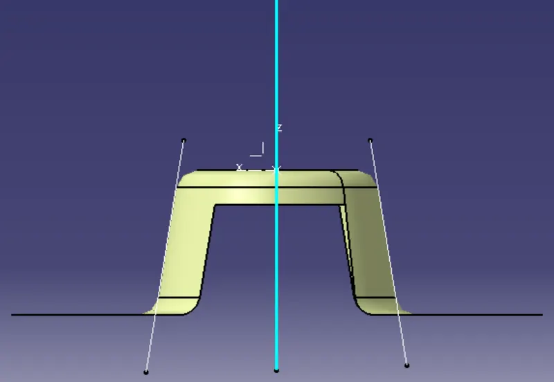
- For the tooling in the Y direction make lines that are parallel to the two side walls when viewed from the YZ plane.
- Now create a bisecting line to the two lines we created in the previous step. This will be our tooling that clears the Y direction.
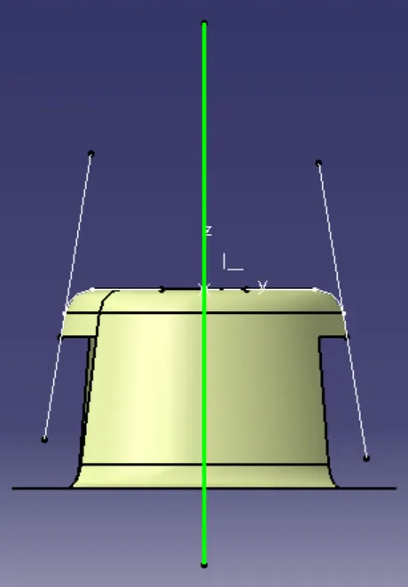
- To get the final tooling axis that will clear both the X & Y direction, create a bisecting line for the tooling axis created based on X & Y walls direction. This line will be our final tooling axis.
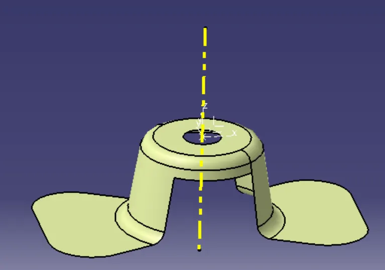
3) DRAFTING ANALYSIS
- Now we have to ensure our part is toolable based on our tooling axis. For that we will perform DRAFT ANALYSIS on our part to ease out the ejection of part from the mold.
- Select the feature draft analysis option, drag and drop the compass on to the tooling axis.
- Now click on the body once you lock the compass position.
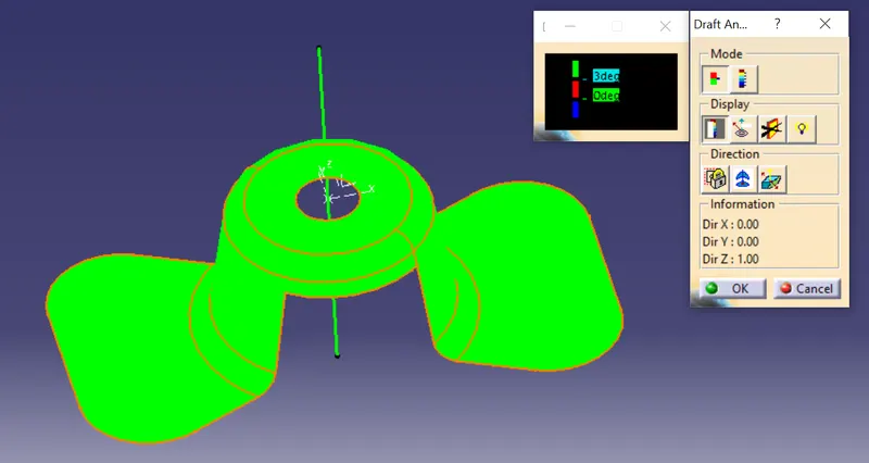
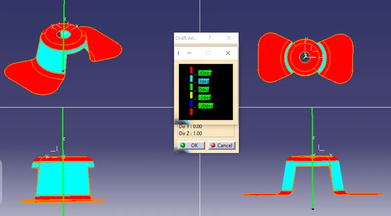
- Under the mode you can choose the range of angle that you want the analysis to display. We can see that by inputing minimum requirement of 3 degree draft angle. Our tooling direction clears all the surfaces.