Week 9 - Project 1 - Door Applique Design with Engineering Features
Project Title : DESIGN APPLIQUE DESIGN WITH ENGINEERING FEATURES.
Objective :
To create a door applique and door attachment from the given class-A surfaces and to create engineering features to fit the component in the main surface.
Introduction :
Engineering feature are the extensions on the plastic components available on the class -B surface such as ribs, screw bosses, heat stakes, locaters and dog houses which help fix the plastic component to the main surface and avoid plastic defects while manufacturing the component through mould process. The feature such as heat stakes are to be assembled on the main component (B-surface).
Procedure :
Create the tooling axis for class-A surface following the steps below
- Create a point in the middle of the component.
- Create a line perpendicular to the surface setting the created point as a base.
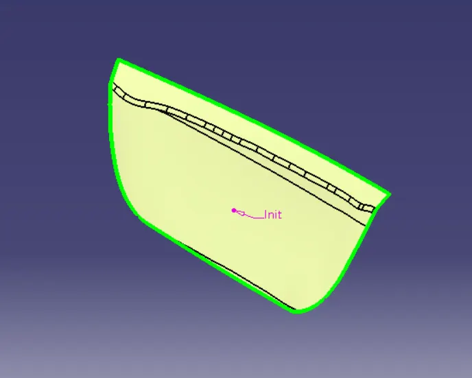
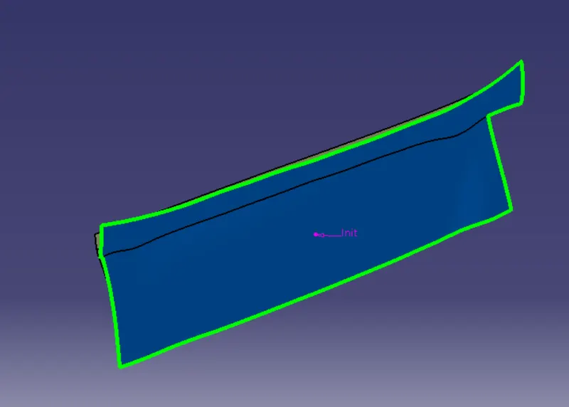
The obtained linne is said to be the main tooling axis
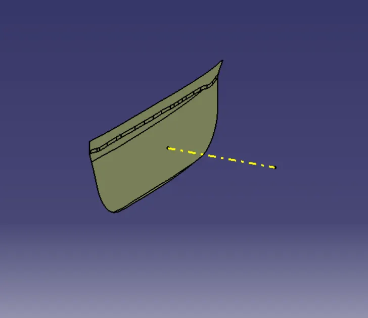
a) Creation of class-B surface:-
- Extract the plane surface from the class-A surface neglecting the fillet surfaces.
- Untrim the surfaces from the extracted surfaces to get the actual shape of the surfaces.
- The untrimmed surfaces should be intersecting with each other. If not intersecting extrapolated the surfaces.
- The thickness of the component is to be maintained at 2.5mm. So offset extrapolated surfaces setting 2.5mm as the offset value.
- Trim the surface as per the shape of the class-A surface.
- Create fillet for the component as per the Class-A surface.
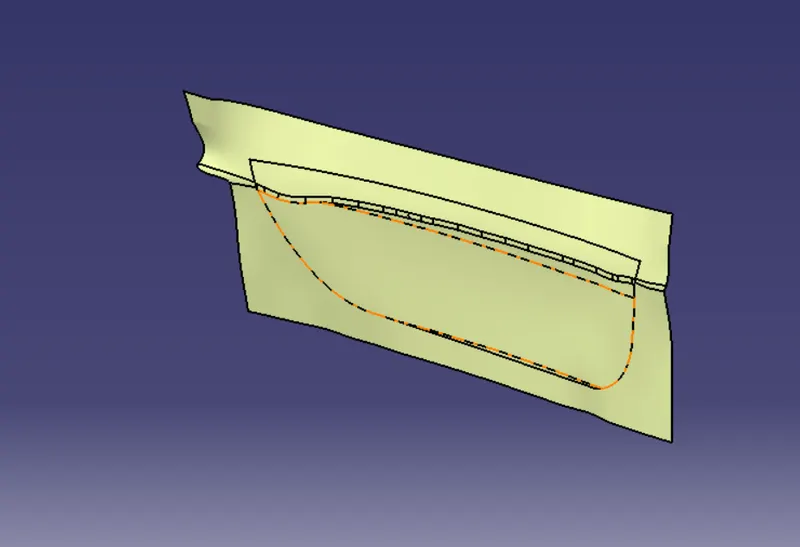
b) Creation of Class-C Surface :-
- Extract the edge lines for the class-A surface using multiple extract option.
- Create edge surface from class-A surface using sweep option.
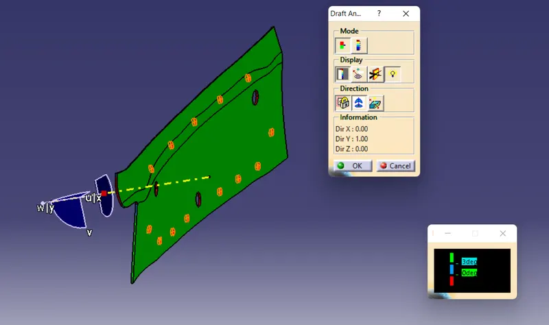
- Set sweep mode to draft direction, Select the extrated lines ass guide curve and tooling axis as the draft direction. Set the sweep angle as 3 degree and the length of sweep more than 2.5mm.
- Now trime the class-B and C surfaces as required to create a thickness of the component.
- After trimming the class-B and C surface join the class-A surface together.
- Now create a solid component for a closed surface component using the closed surface feature in the part design.
- Now the engineering features that is locators and heat stakes should be created for the component.
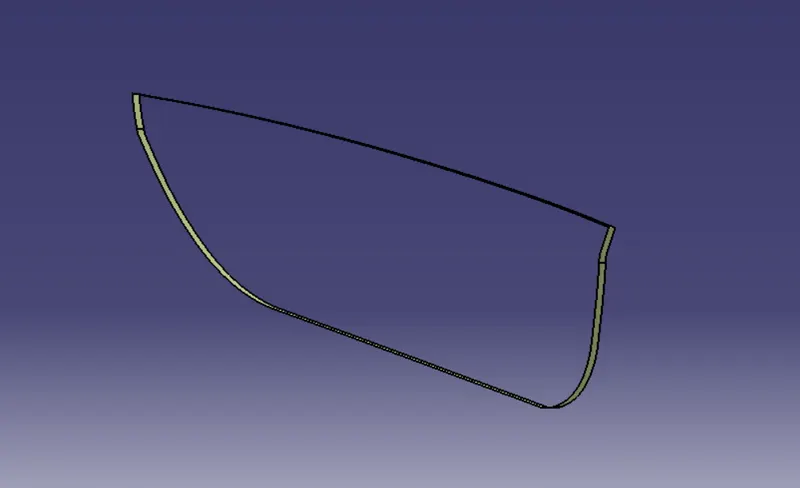
c) Creation of Locators :-
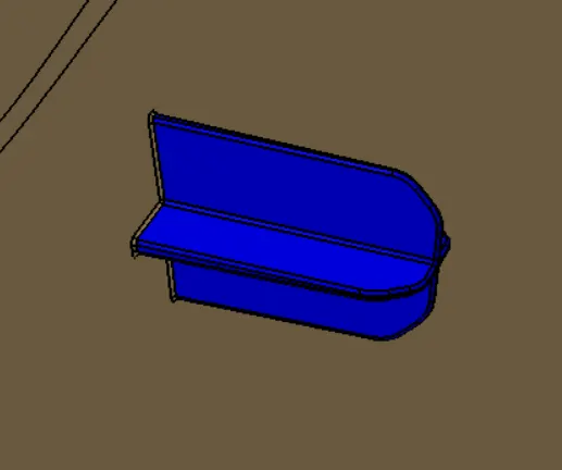
- There are two types of locators. They are 4 way and 2 way locators.
- Considering the 4 way locator create a sketch for the locator.
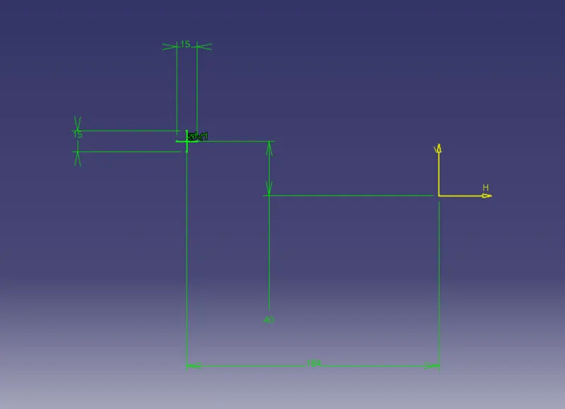
- Now create a new part body for the locator and pad the sketches such that it intersects through the surfaces of the door applique and the door attachment surface sample.
- Create a draft for the locator walls up to 0.5 degree.
- Create chamfer angle for the edges of the locator as 45 degree and length up to 3mm. Create fillets for the edges of the component up to 0.25 mm.
- There are two locators fixed for the component.
- Create a two-Way locator as done for the above 4 way locator except the sketches is to be created.
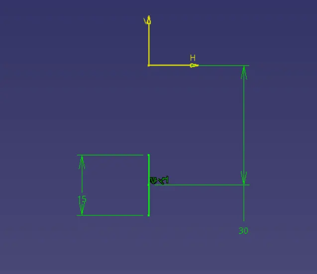
- Draft the created cylinder up to 0.5 degree and translate 2 more cylinders for the remaining 2 locators as done for placing the locators.
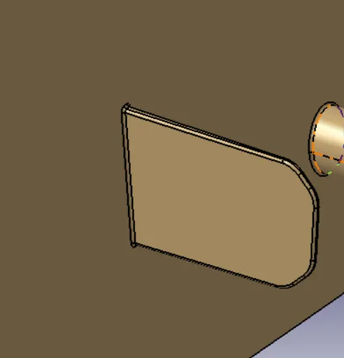
- The gaps between the locator and the opening should be around 0.1mm.
d) Creation of Heat Stakes :-
- Create a new sketch for the heat stake.
- Create a new part body and pad the sketch as done for the locators.
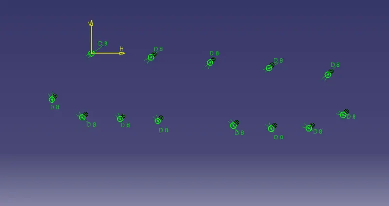
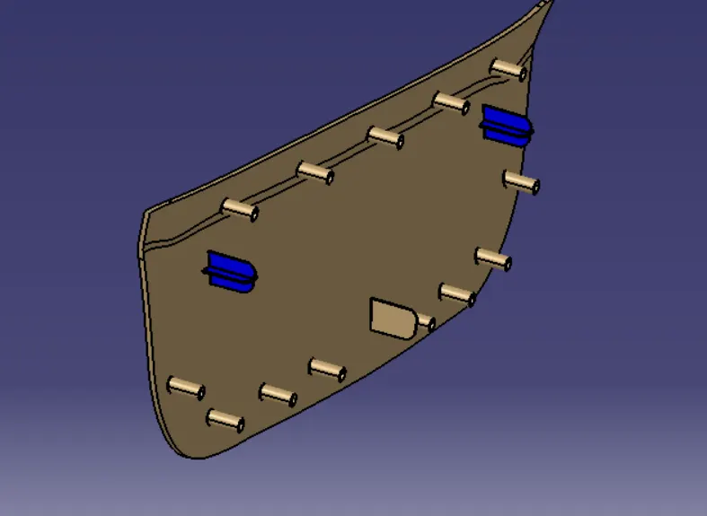
- Similarly, 12 more features are to be created on the door applique.
- Create an offset for the boundary lines which are created in C surface creation around 5mm on the component.
- Now create 12 points on the offset lines maintaing the distance around 50mm from each other.
- Translate the heat stakes as done for the locator taking the created points as references.
- Now create the openings for the heat stakes on the door attachment sample as done for the locators maintaining the gap of 0.5mm between the heat stakes and the openings.
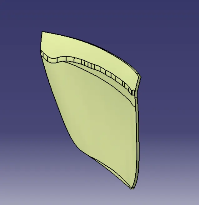
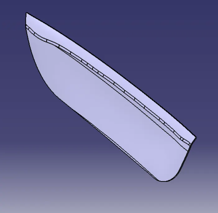
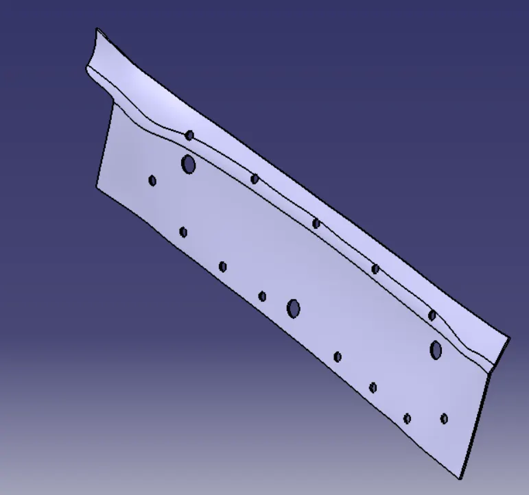
Door applique part after joining its class A, B and C surfaces.
4-Wat Locators.
2-Way Locator.
Heat stakes creation. Create and Translated to each and every point.
Union trimmed by removing the faces we don't need.
Door Attachment.
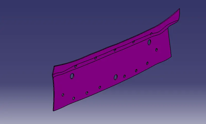
The hole have been created from the above reference points.
Final Part :
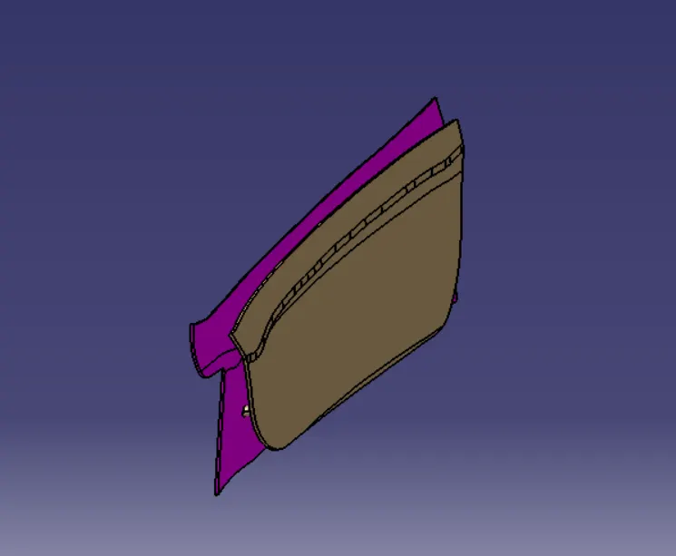
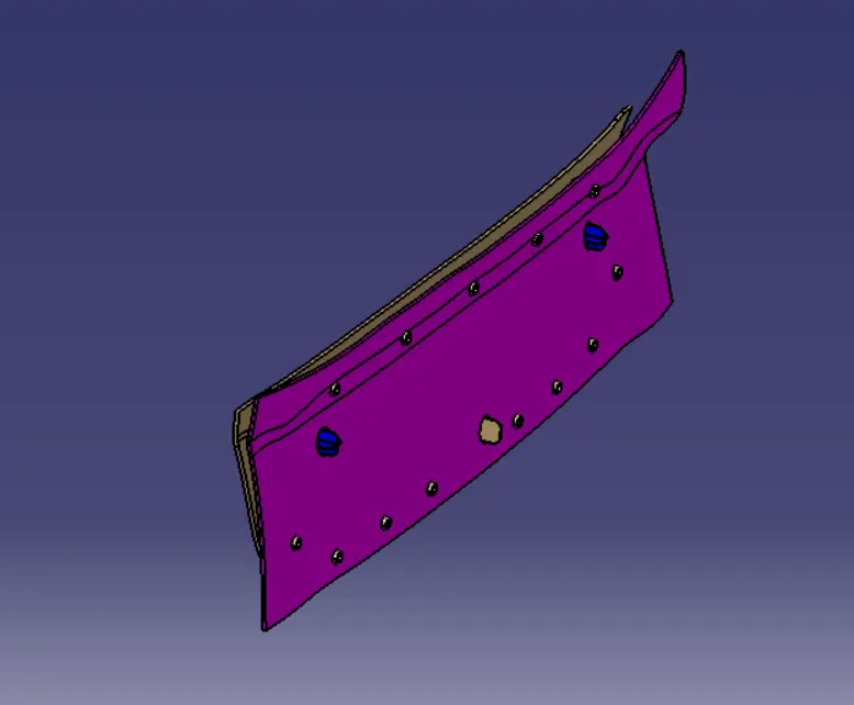
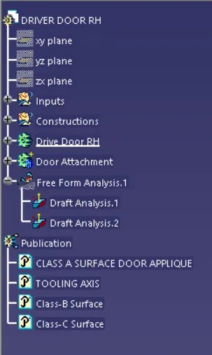
Draft Analysis :
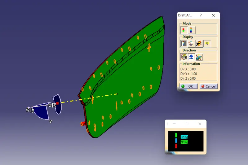
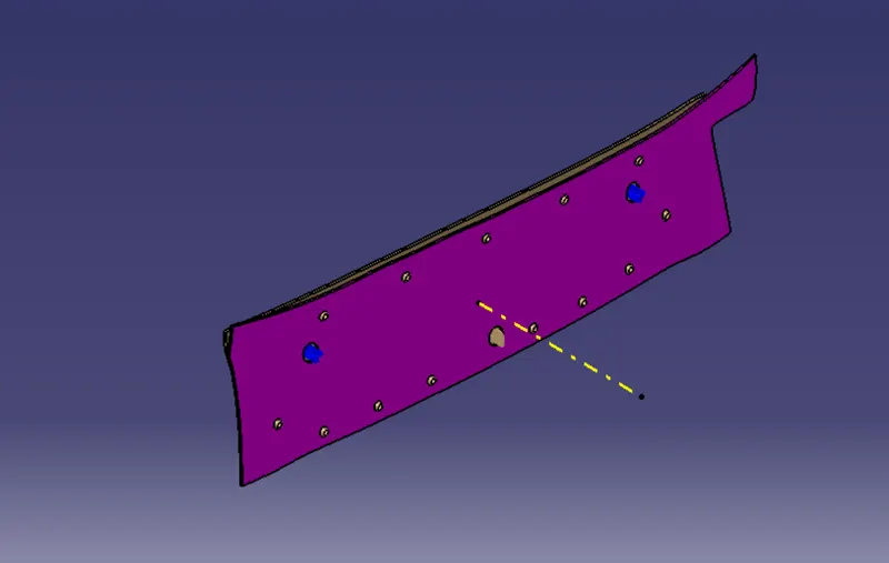
VIEWS OF Door Applique Design :
- Front View
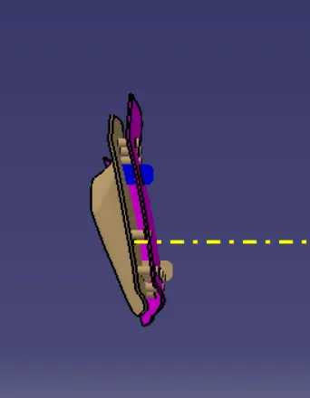
- Back View
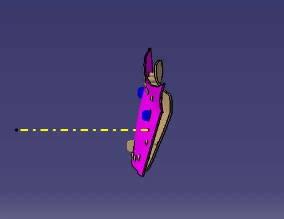
- Left View
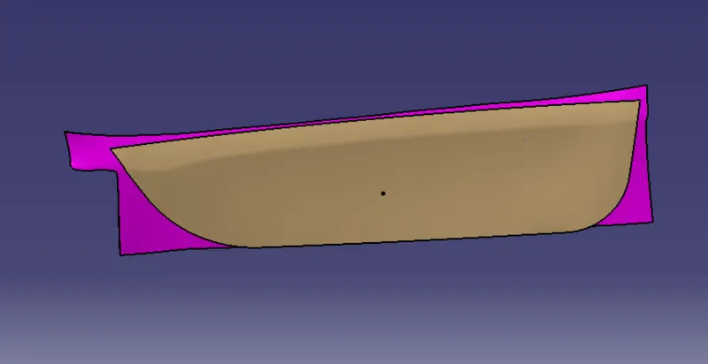
- Right View
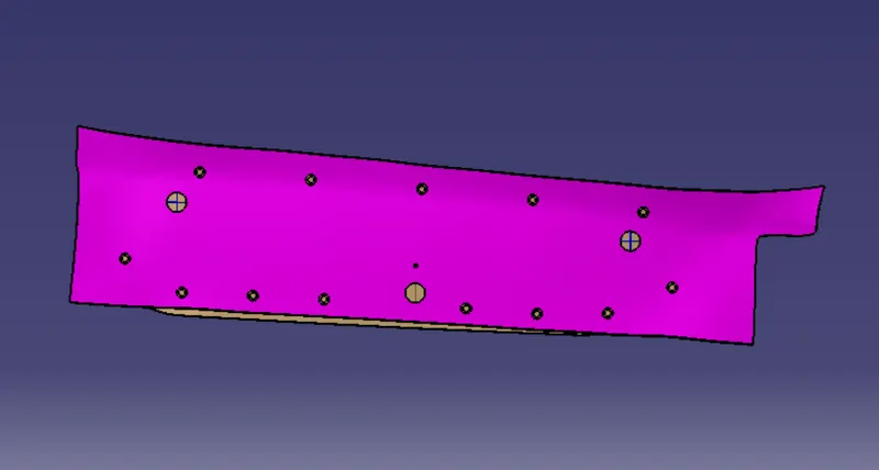
- Top View
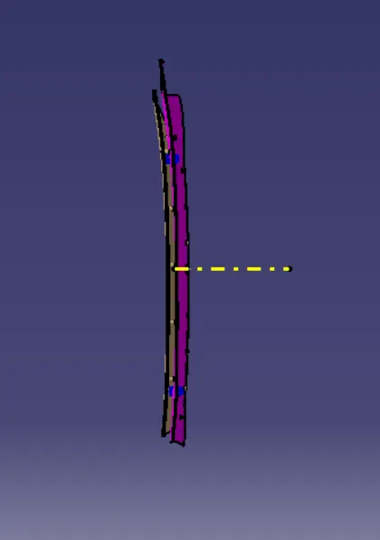
- Bottom View
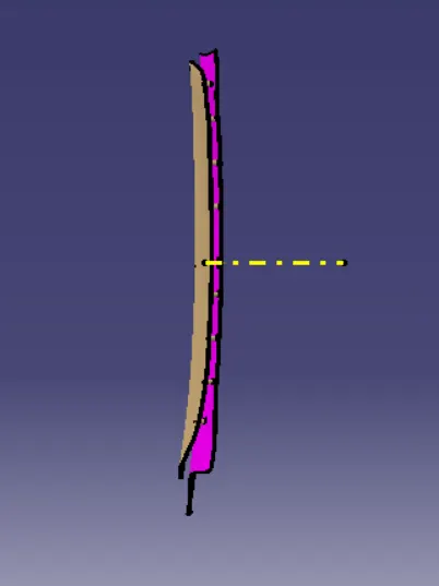
- Isometric View
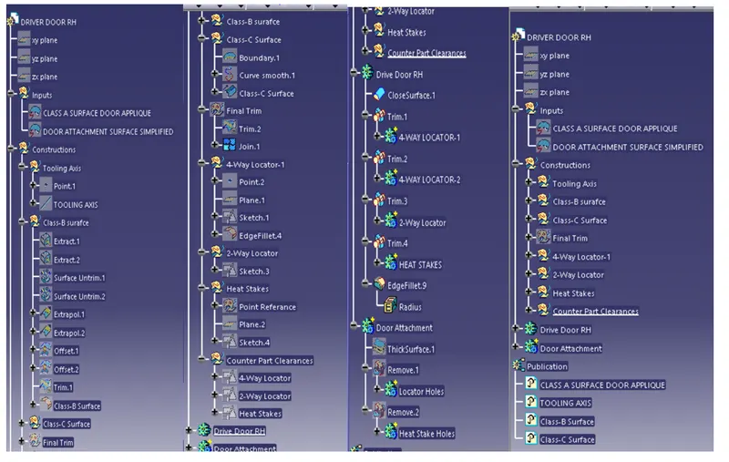
Design tree Structure :