Week 9 - Project 1 - Door Applique Design with Engineering Features
DOOR APPLIQUE DESIGN WITH ENGINEERING FEATURES
AIM: To create a solid body of a given door applique and to create the locators and heat stakes on it as per design standards.
INTRODUCTION:
Heat staking
Heat staking also known as thermoplastic staking is the process of joining two dissimilar materials together. In heat staking, we use local heating and cooling to raise the temperature of plastic components and allow plastic reforming to be carried out. This reforming can be used in a wide variety of applications.
Applications range from staking plastic bosses for assembly of car door panels to joining PCBs to plastic housings. Benefits of this technique include; no vibration damage, no particulates, the ability to stake metalized coated applications, and the capability to stake in difficult to access or restricted areas.
Process
When an electrical current flows through the heating tip, the electrical resistance creates the heating effect. The heat staking tip is brought into contact with the thermoplastic part to be reformed. The heating tip is then heated by direct electrical heating within the tip for a short period of time. The heated tip softens the plastic material and forms the melted plastic into the shape of the tip.
Compressed air is then applied to cool the tip and the formed plastic. Multiple points including multiple polymers can be staked simultaneously. Cycle time is influenced by the volume of polymer to be reformed. Heat staking technology can be implemented in varying levels of sophistication according to customer requirements. From simple time-controlled open-loop systems to sophisticated closed-loop systems with temperature feedback.
PROCEDURE:
- Tooling axis
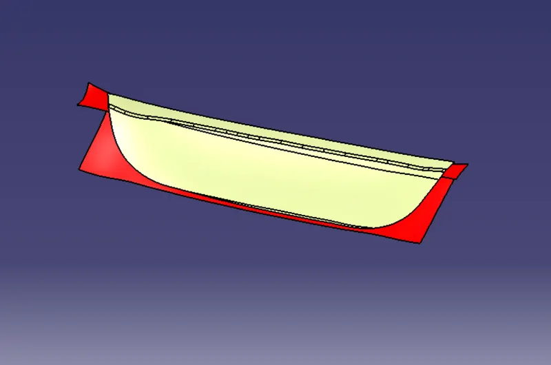
The tooling axis is nothing but the direction in which the core and cavity open and close. The design engineer works are to analyze the Class-A surface and find out the best possible tooling direction keeping in mind all the draft angle is with respect to the tooling axis so that the component can be easily ejected from the moulds.
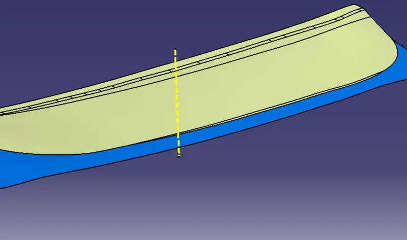
- Class A surface
In automotive design, a class A surface is any of a set of freeform surfaces of high efficiency and quality. Although strictly, It is nothing more than saying the surfaces have curvature and tangency alignment-to ideal aesthetical reflection quality, many people interpret class A surfaces to have G2 curvature continuity to one another. Class A surfacing is done using computer-aided industrial design applications. Class A surface model is also called “digital sculptors” in the industry. Industrial designers develop their design styling through the A- surface, the physical surface the end-user can feel, touch, see, etc.
- Class B surface
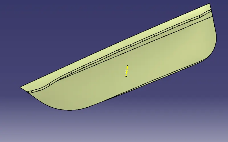
Represent internal or functional surfaces. This cluster example includes derived surfaces created by offset operations from class A surfaces to define the thickness of the material. In this file, it is important to link class B surfaces geometrically to enable an adaptation to class A surfaces automatically in case of styling change.
After creating the tooling axis, the B surface is to be created which is nothing but the surface parallel to the A surface. B surface contains all the fillets and the edges which the A surface contains.
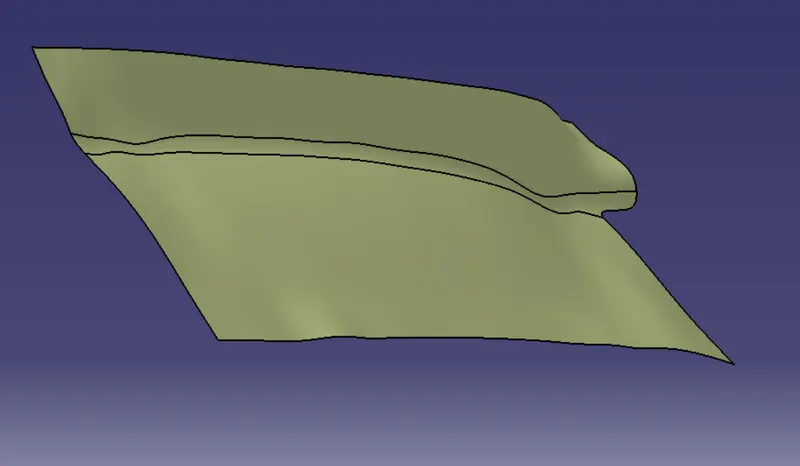
- Class C surface
Class C surface is swept along the boundary of class A at an angle perpendicular to the Class A surface with respect to the tooling axis direction with a draft angle of 3 degrees.
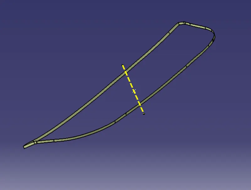
- Joining Class A, B, and C surfaces
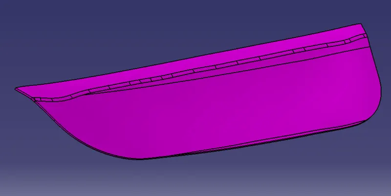
After finishing all the 3 surfaces join the class A and C surfaces together using the join command. Now, the joined surfaces are then trimmed with a class B surface to form a closed surface.
- Draft analysis
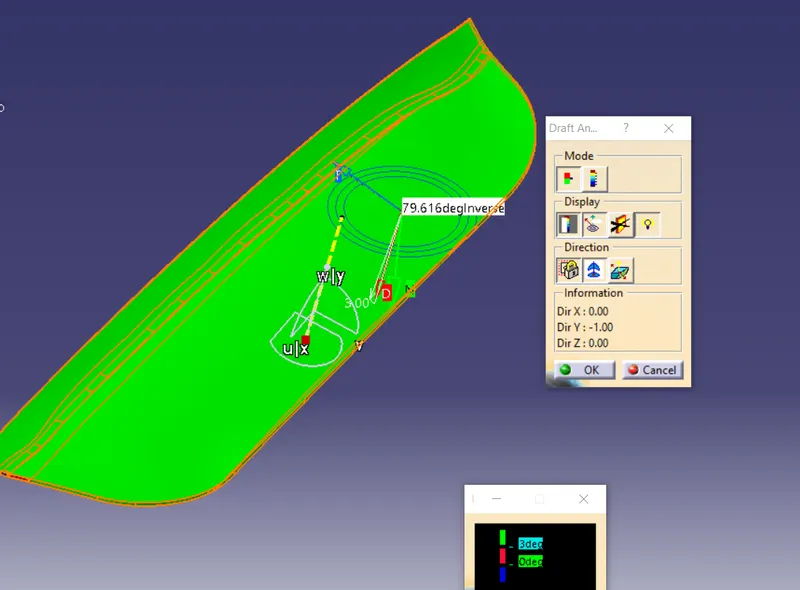
The draft analysis command enables you to detect if the part you drafted will be easily removed. This type of analysis is performed based on color ranges identifying zones on the analyzed element where the deviation from the draft direction at any point, corresponds to specified values.
Draft angles are very important in thermoforming product design. If the product is formed onto a female or negative mold, it shrinks away from the mold sidewalls. As a result, a true female or negative product can be thermoformed with vertical walls having zero draft angles.
- Creating 2 and 4-way locators and Heat stakes
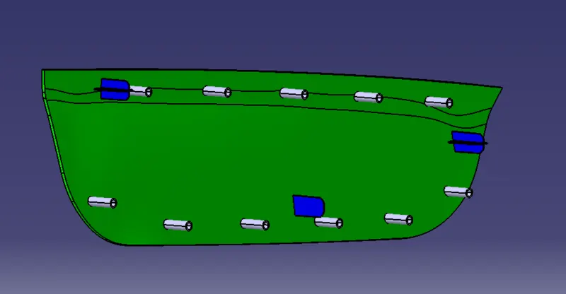
4-way locators mean you prevent movement at 2 axes (+x, -x, +y, -y) on the plane. Generally, you have a cylindrical pin on the fixture and a circular hole at the workpiece part.
2-way locators mean you prevent movement only at 1 axis on the plane. While creating the locators we need to follow the design rules to create the ribs in order to avoid the sink marks on the components.
Heat staking is a pulsed-heat process to join two or more parts out of which one at least is made of plastic. The process is to deform the plastic material using heat and force at a set process time. The bond is made by partially deforming the plastic part in order to fix the order.
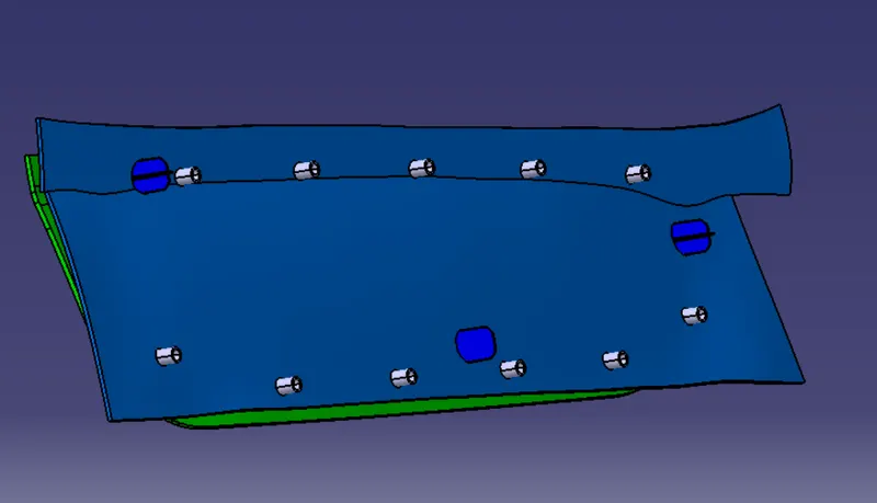
Once done with the design of locators and heat stakes we need to design the counter holes in the mating parts with standard clearances as shown in the picture below.
CONCLUSION:
- Thus the door applique is developed by using a given class-A surface.
- 2 and 4-way locators have been designed in order to fix the position of the applique with the mating door panel and also designed the heat stakes which are used to fix the component with the mating panel by melting.